Conceptual Design and Preliminary Verification of a Double-bunch Switchyard for SXFEL
Yongfang Liu, Jin Tong, Sheying Li, Yizhou Jiang, Qibing Yuan, and Bo Liu*
Shanghai Advanced Research Institute
Chinese Academy of Sciences, Shanghai 201204, China
bo.liu@sari.ac.cn
Submitted On: December 22, 2023; Accepted On: November 5, 2024
ABSTRACT
The Shanghai soft X-ray free-electron laser (SXFEL) is the first X-ray free-electron laser (FEL) user facility in China. To improve the utilization efficiency of the linear accelerator, SXFEL plans to upgrade to double-bunch mode with a bunch time separation of 100 ns and a maximum repetition rate of 50 Hz. A new conceptual beam distribution system is designed to separate the double beam bunch-by-bunch. Conceptual design and prototype implementation of a double-bunch separation system was implemented. The beam distribution system consists of four in-vacuum kicker magnets and one Lambertson septum magnet. This paper presents the design considerations and preliminary verification of a beam bunch distribution system. Distributed magnets and excitation power supply are introduced in detail. The relevant simulation and experimental results of the magnets and pulsed power supply are introducedalso.
Index Terms: Beam distribution system, double-bunch separation, kicker magnet, pulsed power supply, septum magnet.
I. INTRODUCTION
The Shanghai soft X-ray free-electron laser (SXFEL), the first soft X-ray free-electron laser (FEL) facility in China, is a fourth-generation light source [1]. The SXFEL was made available to domestic and foreign users at the end of 2022 [2]. Two undulator lines produce FEL radiation with the shortest wavelength of approximately 2 nm. The beam distribution system, which is used for deflecting beam bunches with a specified mode, is located between the linear accelerator and the undulator lines. To enhance the utilization efficiency of the SXFEL, the linear accelerator will be upgraded from single-electron bunch mode with a 50-Hz maximum repetition frequency to double-electron bunch mode [3]. The two bunches, which are separated in time by 100 ns, will be distributed to two different undulator lines by the beam distribution system [4]. The existing beam distribution system is equipped with a single 54-mrad deflection angle kicker magnet with a 30-μs pulsed width power supply [5]. Beam distribution systems are designed for the world’s Most FEL. For example, the beam distribution system of SwissFEL comprises a fast kicker magnet and a Lambertson septum magnet. A resonant kicker is used to separate the two bunches separated in time by 28 ns [6–7]. SACLA deflects interval beam bunches of 16.7 ms to two undulator lines using a kicker magnet and a septum magnet [8]. The beam distribution system of LCLS-II is composed of a transmission line kicker magnet and a direct current septum magnet to distribute 929-kHz beam bunches into different undulator lines [9]. The beam distribution system of EXFEL uses two types of kicker magnets and a septum magnet [10–11]. Using a single kicker magnet, the SXFEL facility separates beam bunches of 20 ms into two undulator lines [12–13]. Nevertheless, the existing beam distribution kicker magnet of the SXFEL cannot meet the capacity requirements for an increasing or decreasing edge of less than 100 ns. To meet the requirements of the new beam distribution mode, the current beam distribution system needs to be upgraded. Figure 1 shows the configuration of the new beam distribution system. It deflects double electron bunches with an energy of 1.5 GeV to the SBP and SUD undulator lines. It comprises four kicker magnets and a DC Lambertson magnet. When the kicker magnets are activated, four kicker magnets deflect the beam bunch vertically by 5.2 mrad. Afterward, the beam bunch passes through the field-free region of the DC Lambertson magnet with a vertical distance of approximately 16 mm. Binding with the magnet downstream, the beam bunch in this case is transmitted to the SBP undulator line. When the kicker magnets are turned off, the beam bunch passes through the field region of the DC Lambertson magnet with a horizontal deflection angle of 54 mrad. In this case, the beam bunch is transmitted to the SUD undulator line. Table 1 gives a summary of the design parameters of the distribution magnets. To meet these requirements, four 300-mm lump-inductance kicker magnets with a fast leading edge pulse driver were designed in this study. A DC Lambertson magnet with a high main magnetic field and a low leakage field was selected [14–15]. This paper presents the conceptual design and preliminary verification of the magnet design and the source of excitation energy. In the present study, the purpose of employing a thyratron was to achieve a rising edge of less than 100 ns using a lumped-inductance kicker magnet with a 1-μH inductance and a Lambertson magnet, ensuring main-field uniformity and a low-leakage magnetic field. In this study, the utilization of a thyratron aims to achieve a rising edge of less than 100 ns of lumped inductance kicker magnet with 1 μH inductance and a Lambertson magnet ensuring main field uniformity and small leakage magneticfield.
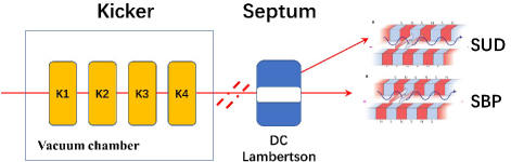
Figure 1: Configuration of the beam distribution system: K1-K4 are kicker magnets, SUD and SBP are the two undulator lines.
Table 1: Design parameters of the distribution magnets
| Parameter | KickerMagnet | SeptumMagnet |
| Magnet type | Lumped-inductance | Lambertson |
| Current shape | Trapezoidal wave | DC |
| Total deflection | 5.2 mrad | 54 mrad |
| Deflecting direction | Vertical | Horizontal |
| Leading edge | 100 ns | — |
| Pulse repetition rate | 50 Hz | — |
| Amplitude stability | 200 ppm | 50 ppm |
| Leakage field ratio | — | 0.1% |
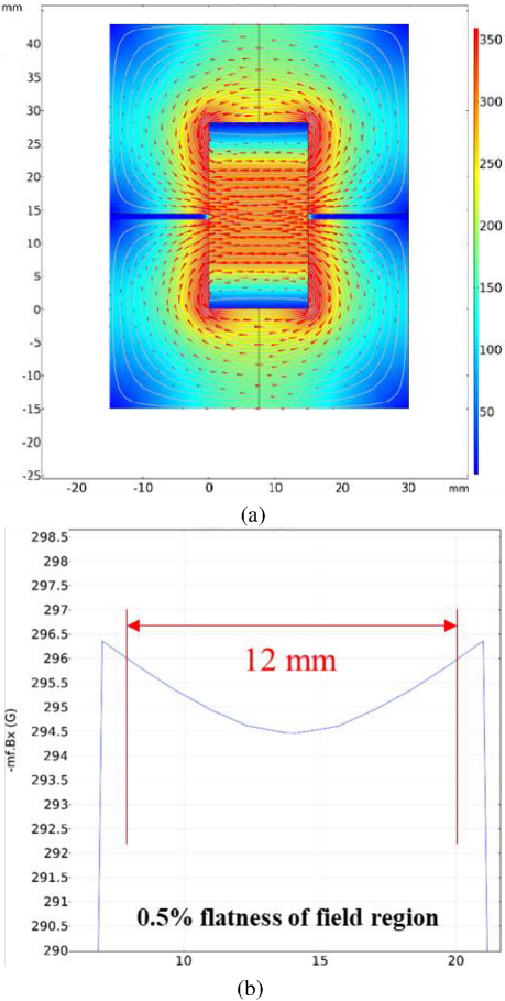
Figure 2: Electromagnetic simulation results of cross-section: (a) magnetic field distribution for 2D and (b) good field region.
II. KICKER MAGNET AND PULSED POWER SUPPLY
A. Kicker magnet design
The kicker magnet was a single-turn lumped-inductance type. Kicker inductance can be approximately calculated by equation (1):
| (1) |
where denotes the vacuum permeability, N is the number of turns, is the distance between the go and return exciting current conductors, is the gap width of the ferrite core, and is the effective length of the magnet. To reduce the inductance of the kicker magnet, each kicker had a length of 300 mm. Four kicker magnets of the same design were placed in one vacuum chamber. Driven by a single pulsed power supply, each kicker provided a deflection capability of 1.3 mrad, requiring a magnetic flux density of 230 gauss. The NiZn soft magnetic ferrite was proposed as the core material for its high frequency, high resistivity, and low loss characteristics. Although the in-vacuum structure could reduce the power consumption to some extent, it could cause cooling problems as well. Figure 2 shows the results of the Comsol electromagnetic simulation. The dimensions of the cross-section of each kicker magnet are shown in Fig. 2 (a). The core structure of the magnet corresponded to the window shape. Oxygen-free copper with less than 0.05% oxygen was used as the core material. Electromagnetic simulations were conducted using electromagnetic software to analyze the distribution of the magnetic flux intensity, a good field region, and integral strength along the beam direction. Figure 2 (b) shows that the flatness of a good field region is greater than 12 mm. Figure 3 displays the magnetic field distribution along the beam direction. The results of the simulations suggested that the integral strength along the beam direction could meet the requirements.

Figure 3: Simulation results of three-dimensional analysis: (a) magnetic field distribution for 3D and (b) magnetic field distribution along the beam direction.
B. Pulsed power supply design
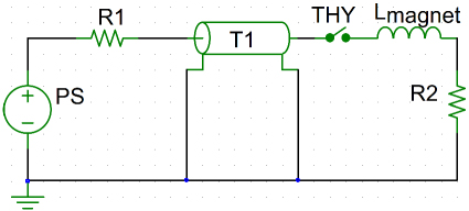
Figure 4: Schematic diagram of the pulsed excitation power supply.
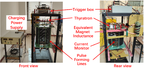
Figure 5: Test bunch of the pulsed excitation power supply.
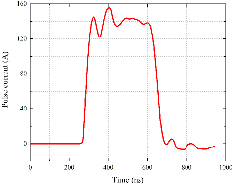
Figure 6: Experimental result of pulse waveform.
To separate the 100-ns beam bunch, the pulsed power supply needed to perform with a fast pulse edge. The pulsed power supply was based on the charging and discharging of pulse-forming lines controlled by a thyratron. The rate of increase in anode current was limited to 50 kA/s. Figure 4 shows the schematic diagram of the pulsed excitation power supply. In the impedance-matching condition, the characteristic impedance of T1 was equal to R2. This time constant is expressed in equation (2):
| (2) |
where L is the inductance of the kicker magnet and Z is the characteristic impedance of the PFL. Figure 5 illustrates the test bunch of the pulsed excitation power supply, while Fig. 6 shows the preliminary experimental result of the pulse waveform with an inductance load equal to that of the kicker magnet. The leading edge was 80 ns, with an equivalent kicker magnet inductance. The pulse flat-tops could be further tuned for a better flatness.
III. SEPTUM MAGNET AND POWER SUPPLY
A. Septum magnet design
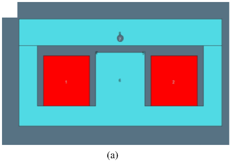
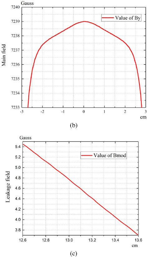
Figure 7: Lambertson magnet simulation result of cross-section: (a) cross-section model of Lambertson magnet, (b) main field region, and (c) leakage field at the center of field-free region.
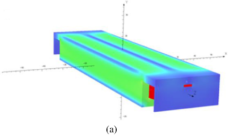
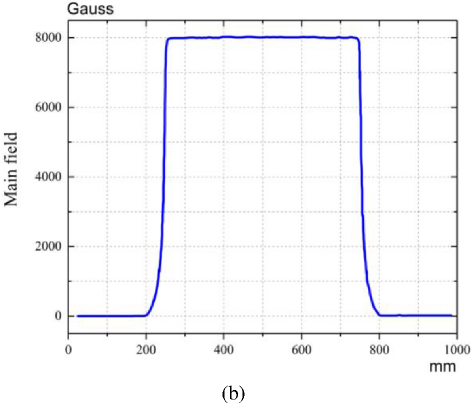
Figure 8: Lambertson magnet simulation result of three-dimensional analysis: (a) magnetic field distribution for 3D and (b) magnetic field distribution along the beam direction in main field region.
The septum magnet was of the Lambertson type. The principle of operation of the Lambertson septum was that high-permeability materials could function with almost any type of leakage magnetic field. According to the system layout and physical design of the SXFEL, the vertical distance between the deflected and undeflected beams at the entrance of the Lambertson magnet was 16 mm. The Lambertson magnet was designed to be 400 mm long. A main magnetic field of 0.7 T and a uniform range of at least 11 mm were required to deflect the electron beam horizontally by 54 mrad. The main-field uniformity in the Lambertson gap needed to be higher than 0.1% to introduce the smallest possible energy dispersion into the high-energy electron beam, whereas the leakage field integral needed to be less than 0.1%. With DC excitation current, the core of the Lambertson magnet was made of solid DT4 iron, which has good electromagnetic properties. The field-free region was designed to be a circular vacuum hole with a radius of 5 mm. At the same time, the vacuum hole was placed horizontally 7.5 mm further from the center of the bottom pole to reduce the width and relative cost of the magnet. To improve the main-field uniformity, two shims were installed on both sides of the bottom pole. The cross-section model of the Lambertson magnet was simulated using OPERA. Sufficient project margin was reserved around the coil to ensure the installation of the coil and to make the simulation as close to reality as possible. A TOSCA Magnetic Analysis in OPERA-3D was used to simulate the three-dimensional model. The simulation results are presented in Figs. 7 and 8.
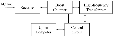
Figure 9: Functional block diagram of septum excitation power supply.
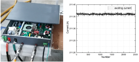
Figure 10: The picture of DC excitation power supply and its current measurement result.
B. DC excitation power supply
The excitation current for the Lambertson magnet was direct current (DC), provided by a DC switch power supply. Figure 9 shows the functional block diagram of the septum excitation power supply. Figure 10 pictorially shows the DC excitation power supply and presents the current measurement results. The current output stability of this power supply was less than 50 ppm.
IV. CONCLUSION
This paper presented a study of the 100-ns double-beam bunch distribution system for SXFEL. The system included four vertical kicker magnets and one horizontal Lambertson magnet. The kicker magnets are based on in-vacuum lumped-inductance technology. The design parameters and simulation results of the kicker and septum were also analyzed. This study validated the feasibility of the 100-ns kicker leading edge pulsed power supply. Prototypes of the kicker and the Lambertson magnet are currently being processed and developed. Further studies on beam impedance effect and nonlinearities are being evaluated.
ACKNOWLEDGMENT
Project supported by the National Natural Science Foundation of China (No. 12005282) and Youth Innovation Promotion Association of Chinese Academy of Sciences (No. 2021283).
REFERENCES
[1] Z. Zhao, “The SXFEL upgrade: From test facility to user facility,” Applied Sciences, vol. 12, no. 1, p. 176, 2021.
[2] Z. Zhao, D. Wang, Q. Gu, L. Yin, G. Fang, M. Gu, Y. Leng, Q. Zhou, B. Liu, C. Tang, W. Huang, Z. Liu, and H. Jiang, “SXFEL: A soft X-ray free electron laser in China,” Synchrotron Radiation News, vol. 30, no. 6, pp. 29-33, 2017.
[3] M. H. Song, C. Feng, D. Huang, H. Deng, B. Liu, and D. Wang, “Wakefields studies for the SXFEL user facility,” Nuclear Science and Techniques, vol. 28, no. 7, p. 90, 2017.
[4] Y.-F. Liu, H. Matsumoto, M. Gu, G.-Q. Li, and S. Li, “Design of an oil-immersed pulse modulator for X-band 50-MW Klystron,” IEEE Transactions on Plasma Science, vol. 51, no. 3, pp. 802-807, Mar. 2023.
[5] M. Paraliev, S. Dordevic, R. Ganter, C. H. Gough, N. Hiller, R.A. Krempaská, and D. Voulot, “Commissioning and stability studies of the SwissFEL bunch-separation system,” in Proceedings of FEL2019, Hamburg, Germany, p. 404-407, Aug. 2019.
[6] T. Hara, K. Fukami, T. Inagaki, H. Kawaguchi, R. Kinjo, C. Kondo, Y. Otake, Y. Tajiri, H. Takebe, K. Togawa, T. Yoshino, H. Tanaka, and T. Ishikawa, “Pulse-by-pulse multi-beam-line operation for X-ray free-electron lasers,” Phys. Rev. Accel. Beams, vol. 19, p. 020703, 2016.
[7] T. Beukers, M. Nguyen, and T. Tang, “Discrete element transmission line beam spreader kickers for LCLS-II,” in 2018 IEEE International Power Modulator and High Voltage Conference (IPMHVC), Jackson, WY, June 2018.
[8] F. Obier, W. Decking, M. Hüning, and J. Wortmann, “Fast kicker system for European XFEL beam distribution,” in Proceedings of the 39th International Free-Electron Laser Conference, Hamburg, Germany, p. 353-356, Aug. 2019.
[9] S. Chen, R. Wang, H. Deng, C. Feng, H. X. Deng, X. Fu, and B. Liu, “Design of the beam switchyard of a soft X-ray FEL user facility in Shanghai,” in IPAC2018, Vancouver, BC, pp. 4456-4459, May 2018.
[10] R. Zhao, M. Gu, and D. Wang, “A new design of Lambertson magnet with true zero field region,” Phys. Scr., vol. 95, p. 065216, 2020.
[11] R. Zhao, M. Gu, and D. Wang, “A new way to improve the main magnetic field uniformity of a Lambertson magnet,” Phys. Scr., vol. 94, p. 105804, 2019.
[12] J. Tong and Y. Liu, “Magnetic field analysis and measurement of pulsed septum magnet,” Applied Computational Electromagnetics Society (ACES) Journal, vol. 38, no. 9, pp. 751-755, Sep. 2023.
[13] Y. Liu, Y. Wu, X. Zhou, and J. Tong, “Design of a pulse transformer for X-band klystron,” Applied Computational Electromagnetics Society (ACES) Journal, vol. 38, no. 9, pp. 734-740, Sep. 2023.
[14] Y.-F. Liu, M. Gu, Q.-B. Yuan, R. Wang, J. Tong, and S. Li, “Development of a MHz pulsed power supply for kicker magnet in SHINE,” IEEE Transactions on Power Electronics, vol. 39, no. 4, pp. 4291-4300, Apr. 2024.
[15] Y. Liu, X. Zhou, G. Li, R. Wang, and Q. Yuan, “Design and application of a thyristor-based half-sine pulsed power converter for eddy current septum magnet,” IEEE Transactions on Applied Superconductivity, vol. 34, no. 8, pp. 1-5, Nov. 2024.
BIOGRAPHIES
Yongfang Liu was born in Shandong, China, in 1987. He received the Ph.D. degree from University of Chinese Academy of Sciences (UCAS), Beijing, China, in 2020. His research interest includes pulsed power supply and pulsed magnet technologies, such as pulsed klystron modulators, linear transformer drivers (LTD), particle accelerator injection and extraction magnet, particle accelerator beam distribution magnet and irreversible electroporation pulsed power supply.

Jin Tong graduated from the University of Chinese Academy of Sciences, majoring in Nuclear Technology and Application. Since graduation, he has been engaged in the design of pulse magnets and magnetic measurement systems over years, especially for special magnets used in electron beam injection and extraction systems, such as linear/nonlinear kicker magnets, eddy current septum magnets and Lambertson cutting magnets, which had been designed and researched in large scientific facilities.

Sheying Li received her Ph.D. in electrical engineering from Karlsruhe Institute of Technology (KIT), Germany, in 2022. She is currently working in the group of pulse power supplies at Shanghai Advanced Research Institute (SARI), Chinese Academy of Sciences (CAS). Her research interests mainly include photovoltaic technology for water treatment, energy storage technology, energy management control, and dynamic system control for pulsed power supply.
Yizhou Jiang was born in Jiangsu, China, in 1999. He received the master’s degree in electrical engineering from Shanghai Electric Power University in 2024. He is working in Shanghai Advanced Research Institute (SARI), Chinese Academy of Sciences (CAS).

Qibing Yuan was born in Sichuan, China, in 1977. He graduated from the University of Science and Technology of China. He received a Ph.D. degree in nuclear technology and applications from Shanghai Institute of Applied Physics, Chinese Academy of Sciences, Shanghai, China, in 2008. He is currently a professor at the Shanghai Advanced Research Institute of the Chinese Academy of Sciences. His research interest focuses on particle accelerator control technology of undulator and pulsed power supply.
Bo Liu received his Ph.D. from Institute of High Energy Physics, Chinese Academy of Sciences in 2005. He is currently a professor at the Shanghai Advanced Research Institute of the Chinese Academy of Sciences. His research interest focuses on particle accelerator based light sources.
ACES JOURNAL, Vol. 40, No. 2, 165–171
doi: 10.13052/2025.ACES.J.400210
© 2025 River Publishers