Advanced Perspectives on Metamaterial Integration in Wireless Power Transfer: A Review
Muhammad Sukriyllah Yusri, Mohamad Harris Misran, Tan Kim Geok, Sharul Kamal Abdul Rahim, Norbayah Yusop, Maizatul Alice Meor Said, and Azahari Salleh
1Centre for Telecommunication Research and Innovation
Fakulti Teknologi dan Kejuruteraan Elektronik dan Komputer, Universiti Teknikal Malaysia Melaka, Hang Tuah Jaya 76100, Durian Tunggal, Melaka, Malaysia
M022120002@student.utem.edu.my, harris@utem.edu.my*, norbayah@utem.edu.my, maizatul@utem.edu.my, azahari@utem.edu.my
2Faculty of Engineering and Technology
Multimedia University, Melaka 75440, Malaysia
kgtan@mmu.edu.my*
3Wireless Communication Centre
Universiti Teknologi Malaysia, Skudai 81310, Johor, Malaysia
sharulkamal@utm.my
Submitted On: January 2, 2024; Accepted On: January 14, 2025
ABSTRACT
The field of wireless power transfer (WPT) has recently seen much innovation and improvement and, as a result, there is an ever-increasing need for high power transfer efficiency (PTE) of the WPT systems, as well as enhanced transmission distance for end users. However, some of the currently available WPT systems have a restricted PTE and transfer distance because they use an inductive coupling technique. With this method, the PTE suffers a significant drop as the distance between the transmitter and receiver coils grows. Alternately, magnetic resonance coupling (MRC) is employed as a mid-range WPT solution. For this method, metamaterials (MTMs) are used to increase efficiency by inserting them between the transmitter (Tx) and receiver (Rx) coils. MTMs are artificially manufactured materials that demonstrate unusual electromagnetic properties. These traits include evanescent wave amplification and negative refractive characteristics, both of which have the potential to be employed for the improvement of PTE. This paper offers an in-depth summary of recent research and development in MTM-based WPT systems. In this overview, we examine previously reported MTM-based WPT systems across a range of characteristics, including configuration, operating frequency, size, and PTE. A comparative of the various MTM-based WPT systems is also provided in this paper. PTEs for these systems were also presented against their normalized transfer distances. This study was conducted with the intention of providing a resource for academics studying WPT systems and their practical implementations. This analysis exposes the developments occurring in MTM-based WPT systems.
Index Terms: Inductive power transfer, metamaterials (MTMs), power transfer efficiency (PTE), wireless power transfer (WPT).
I. INTRODUCTION
In today’s environment, electronic devices like mobile phones and laptops need wireless power transmission in order to be charged wirelessly. This not only offers protection against interruptions in the power supply but also enables the devices to charge themselves without the need for a conducting line. Wireless electricity is a method that involves the transmission of electrical energy by means of an electromagnetic field between a transmitter and a receiver. It’s possible that we’ll have access to this kind of technology in the not-too-distant future. Because of this, there is no longer a need for using batteries to power portable gadgets. Radio receivers are necessary for the operation of the system, and the device in question has to be positioned such that it is within range of the transmitter. Electromagnetic connection between the two coils causes the energy to be transferred [1]. The primary operating basis for such systems is the notion of resonant objects efficiently resonating energy while non-resonant things do not.
The history of wireless power transfer (WPT) may be traced back to the latter half of the 19th century and the early part of the 20th century, when various kinds of wireless energy transfer were initially developed and tested by scientists and engineers. Nikola Tesla is frequently cited as the individual who came up with the concept of WPT for the first time. In the early 1890s, he demonstrated the transmission of high frequency alternating current over short distances without the need of wires. The magnetic resonance approach was yet another early type of WPT. It was initially conceived of by Alexander Popov in the latter half of the 19th century. One of the resonant circuits in this approach acts as the energy generator, while the other acts as the energy receiver. This method includes the transmission of energy between two resonant circuits as shown in Fig. 1 [2].
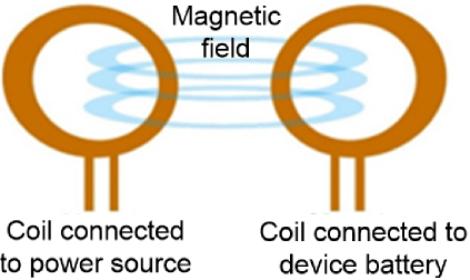
Figure 1: A simple method of wireless power transfer [2].
In the early part of the 20th century, when inductive charging devices for batteries were being developed, the first commercial uses of WPT were put into practice. These systems move energy from a power source, such as a wall-mounted charging station, to a receiver coil in a battery-powered device, such as a toothbrush or shaver, by use of magnetic induction. Other examples of power sources are solar panels and wind turbines.
The WPT method may be broken down into two different subfields, known as near-field and far-field WPT. WPT systems that have a transfer distance that is shorter than their operational wavelength are said to have a near-field configuration. Magnetic resonance coupling (MRC) and inductive coupling WPT are the two technologies most widely used and correlate most closely to this categorization. Nevertheless, while MRC-based WPT can transfer power across a moderate range (cm to m), extending the transfer distance has the consequence of reducing the magnetic coupling between the transmitter (Tx) and receiver (Rx) coils. Hence, the MRC-based WPT system’s transfer distance is limited, and power transfer efficiency (PTE) falls [3]. Radioactive wireless power transfer is a long-range application, better known as far-field energy transfer [4]. In terms of far-field WPT, the microwave energy transfer technique known as radiative WPT falls under this category. Figure 2 shows the different areas of electromagnetic field in wireless power transfer [5]. The radiative WPT process involves power that is emitted from a transmitter antenna and then travels a great distance via the air as it radiates outward. This electromagnetic (EM) wave may be picked up by a rectenna, a combination of a rectifier and an antenna, and converted into direct current (DC) power. PTE is relatively low since radio waves travel in air in an omnidirectional manner, therefore losses occur during long-distance propagation. Moreover, there are challenges in designing a rectenna, such as overcoming challenges in the design of the feeding network to realize impactful beamforming for high PTE, minimizing mutual coupling among both antenna arrays that degrades rectenna performance, and mitigating high losses associated with array feeding networks.
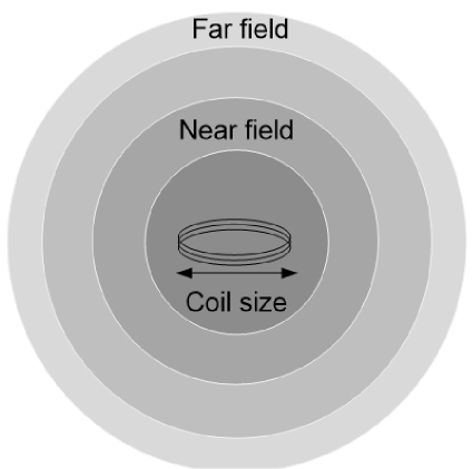
Figure 2: Areas of the electromagnetic field [5].
WPT has received increased attention as a result of the development of new technologies and applications. Some examples of these developments include wireless charging for mobile phones, electric cars, and medical equipment. As the distance between the transmitter and receiver increase in the wireless power transfer system, the transmission efficiency drops. Transmission efficiency may be improved, and the effective power transfer distance can be extended by increasing coil quality factor and magnetic coupling for both the transmitter and receiver coils [6]. Since near-field energy transfer depends on the coupling of the magnetic fields between the two coils, which accounts for its small range, it is additionally categorized as electromagnetic induction. The near-field energy transfer field shrinks exponentially. Power may be transferred over relatively short distances with a high transfer efficiency using near field transmission techniques, commonly referred to as non-radiative methods [7]. It consists of magneto-dynamic coupling, resonant capacitive coupling, resonant inductive coupling, and capacitive power transfer [8]. Additionally, far-field energy transfer is categorized as electromagnetic radiation. Long-range applications benefit from it the most. However, because of the power losses, it is less effective in comparison. It uses microwaves and lasers to convey power [9].
William C. Brown’s presentation of his capacitive methods study in 1961 was a seminal moment in the field’s history. In the study, a systematic approach to transferring power at the microwave level was given. The intrinsic benefit of being able to traverse greater distances may have contributed to the selection of a frequency that is so low as to be practically insignificant. On the other hand, the approach was restricted in that it could only transmit electricity at a low level and had a reduced degree of efficiency. The accompanying misalignment of power transmitter and receiver devices was one of the additional challenges that had to be overcome at this time. This misalignment further contributed to an unpredictable power transfer, which decreased the efficiency of the process.
II. WPT USING INDUCTIVE TECHNIQUES
The utilization of inductive coupling for WPT has garnered considerable attention in contemporary discourse, particularly within domains such as electric vehicle charging, biomedical implants, and consumer electronics [10, 11]. The foundational principle involves the transference of power between two coils, intricately linked through inductive means. In this dynamic, an alternating current within the primary coil engenders a corresponding alternating magnetic field, thereby inducing a current in the secondary coil [12, 13]. The efficiency and efficacy of power delivery are contingent upon a nuanced interplay of factors, including the coupling coefficient, quality factors, operating frequency, coil geometry, and compensation networks [14, 15].
Empirical evidence underscores the pivotal role of resonant compensation networks in optimizing efficiency, yielding a load-independent voltage gain [11, 16]. Prevailing series-series and series-parallel topologies, notably applied in electric vehicle systems, have demonstrated efficiencies reaching 90% [17]. Furthermore, strategies such as achieving zero voltage switching through methodologies like phase shift control contribute substantively to loss mitigation [18]. The scope of inductive coupling extends to wireless battery charging, exemplified by the work of Ragab et al. [19], who devised a photovoltaic charging interface employing inductive coupling and regulating power to the battery through phase control.
Efficiency within the field of magnetic coupling is contingent upon critical parameters. Mutual inductance between coils, dictated by their relative orientation, emerges as a direct determinant of power transfer efficiency [13]. Research findings presented by Shevchenko et al. [20] assert that single-layer coils may manifest superior efficiency in contrast to their double-layer counterparts. Moreover, losses are incurred due to parasitic coupling between non-corresponding coils in multiple input multiple output systems [21]. The ongoing scholarly endeavor is dedicated to optimizing both coupling and compensation mechanisms, thereby augmenting the commercial viability of mid-range inductive WPT. Figure 3 shows a schematic diagram of inductive WPT [22].
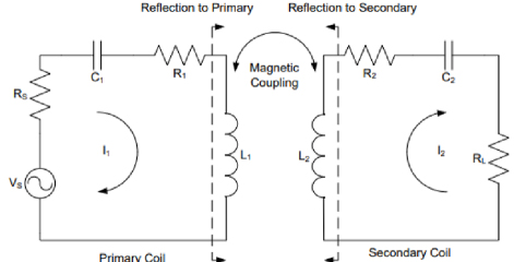
Figure 3: Schematic diagram of inductive WPT [22].
Continuous advancements in magnetic materials, coil structures, and compensation techniques are playing a pivotal role in augmenting the capabilities of inductive WPT systems. A study conducted by Yamada et al. [23] has yielded analytical expressions for mutual inductance in coils featuring ferrite cores, utilizing image theory. The results exhibit a robust alignment with numerical outcomes, facilitating simplified modeling and design considerations. Notably, the field of vehicle charging remains a focal point, with Aziz et al. [24] conducting a comprehensive review of inductive charging developments, encompassing innovations like movable power tracks and methodologies for foreign object detection. These innovations collectively contribute to enabling safe high-power operation.
The significance of compensation networks is underscored in ensuring efficiency across variable coupling and load conditions. In a comparative experimental study by Rehman et al. [25], series-series and series-parallel topologies were assessed, revealing that the latter demonstrated superior efficiency, particularly with larger transmitter coils. Diep et al. [26] further contributed to this discourse by designing an electric vehicle system employing series-series compensation, achieving an impressive average efficiency of 89.5%, even during dynamic charging scenarios. The landscape of converter architectures has also evolved, as evidenced by the introduction of a novel transformerless multilevel inverter for inductive power transfer by Lee et al. [27], realizing an 84% converter efficiency from input to load.
In the field of multiple-device WPT, Vo et al. [28] developed a technique that enables independent control of load voltages by dynamically tuning the transmitter array. Addressing orientation sensitivity challenges, Roberts et al. [29] delved into conformal resonant magnetic coupling, achieving a notable 60% efficiency over a 100 MHz link through the use of compact high-Q resonators. Compatibility strides, exemplified by Wandinger et al. [30], extended the efficiency of inductive transfer through saltwater, opening up novel applications such as underwater charging. Persistent endeavors in modeling resonant conditions [31], optimizing coil structures [32], estimating system parameters [33], and integrating power management solutions [34] collectively lay a robust foundation for the ongoing innovation in mid-range inductive WPT.
Inductive energy transfer results in the production of dipole fields that are aligned longitudinally. As the transmitter and receiver move apart, these fields become weaker. Therefore, the distance that separates the two coils is one of the parameters that influences the efficiency of the power transfer. As a result, the efficiency increases in proportion to the distance between the receiver and the transmitter [34, 35].
III. METHODS TO ENHANCE EFFICIENCY OF POWER TRANSFER
Many investigations have been carried out with the goal of increasing the distance between the coils without effecting efficiency of power transmission.
A. Type of antenna
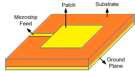
Figure 4: Microstrip patch antenna [36].
As shown in Fig. 4, the antenna radiates from the patch’s width and not its length; the effectiveness of the antenna’s radiation is dependent on the patch’s width [36]. Because of this, the length of the patch has no bearing on the antenna’s ability to radiate (W). When the value of W is low, the amount of radiation emitted is low, and when the value of W is high, the amount of radiation emitted is high [37]. The antenna’s bandwidth is influenced both by the substrate thickness (h) of the dielectric materials and by the value of the parameter W. A greater bandwidth is indicated by a bigger W number. The value of W is one of the factors that determines the gain of the antenna. This value also depends on a number of other characteristics. The greater the value of W, the greater the gain that the antenna provides. The operation of the antenna is determined mostly by the relative permittivity (r) value of the substrate material and, as a result, the h material may be determined.
Research on spiral antennas has been going on for several decades, and these antennas have recently emerged as top contenders for use in applications that need circularly polarized broadband antennas [38]. Spirals can have a single arm or many arms, and they have been implemented both in the form of microstrips and in the form of slots as shown in Fig. 5.
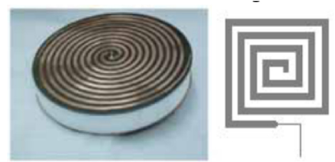
Figure 5: Example of a microstrip circular spiral coil antenna and square spiral antenna [38].
Mirrors serve as the conceptual foundation for this form of microstrip configuration’s use of the radiation principle [38]. The ratio of the front to the rear of the signal grows as the frequency of the signal rises, allowing for the possibility of one-sided radiation.
At a certain frequency, which is determined by the structural properties of the spiral, the direction of the highest radiation will begin to sway in the opposite direction. As frequency continues to increase, the direction of the deflection shifts to both sides of the axis that is perpendicular to the surface of the antenna. Within the dielectric, the height of the slab is stipulated to be around a fourth of the wavelength at the antenna’s center frequency [38]. This height is determined by the antenna.
Therefore, height tends to be equal to one-half of the wavelength at the relevant frequencies when considering the higher frequency bands [38]. When it reaches the spiral plane, the phase of the original signal is exactly the opposite of that of the wave that was reflected by the ground plane. This is because of the phase of the wave that was reflected by the ground plane. Following the superposition of the signals, there is a reduction in the amount of radiation at the broadside, and the main lobe begins to separate.
These antennas have the capacity to resonate in frequencies considerably lower than those that conventional multiband antennas are capable of and, at the same time, they have a very compact size [38]. The extended length of the current route through the conductor area as a result of the spiral shape of this conductor is the critical factor in achieving this level of performance.
B. Multiple coils
By coupling together many coils and transferring their energy to one another, it is possible to create a WPT system that is effective across a considerable distance [39]. In [40], multiple coils, also known as repeater coils or relay resonators, are utilized to supply energy for the load. These multiple coils are arranged in the shape of a domino [40, 41].
Figure 6: Experimental setup for multiple coils [39].
Figure 6 shows the experimental setup for multiple coils where the second coil placed at the center is the repeater. The practicability of the system is severely compromised as a result of the presence of a great number of relay coils between the transmitter and the receiver [42]. In addition to this, the efficiency of the system plummets as the relay coils move further away from their intended location.
C. Resonant coupling
Since Kim [43] published their findings, the use of resonant coupling technology has become more significant in the field of wireless power transmission.
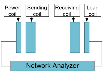
Figure 7: Schematic diagram of resonant coupling [43].
In order to create effective methods of wireless power transfer based on Fig. 7, Kim relied on the ideas developed by Nikola Tesla. Interestingly, Kim demonstrated that electricity could be transmitted across lengths of two meters with an efficiency of just 20%. Despite the fact that this efficiency was somewhat poor, the transmitted power could reach up to a notional value of 50 W at a radio frequency that covered a range of 9.4 MHz. The enhanced influence of radiation as well as the complexity connected with manufacture both served as limitations on the endeavor.
D. High Q-factor
Under the assumption that there is only a weak coupling between particles, power transfer efficiency may be written as stated in [44]. It is plain to observe that the use of high-Q coils is capable of bringing about significant progress in terms of power transfer efficiency.
In [45], the authors suggest a self-resonant structure that is built on a foil layer and has a Q-factor of 1183, as shown in Fig. 8. This structure obtained a power transfer efficiency of 94% at a relatively wide transfer distance in comparison to the solid or Lize wire. In [46], coils with quality factors ranging from 15 to 1000 were used to obtain a PTE of 10% when the transmission distance was about nine times greater than the radius of the coils. However, a high Q-factor will result in significant voltage pressures being placed on the transfer coils. This is because the reactive current or voltage that the coils are expected to handle should be Q-times the actual power current or voltage that is being carried by the coils.
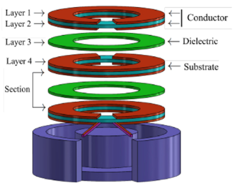
Figure 8: A self-resonant structure [45].
In addition to this, having a high frequency would result in a narrow band, which in turn would need a precise control technique. Both [47] and [48] have underlined how important it is to have a high Q-factor when building a coil with a high efficiency. This may be accomplished by raising the inductance of the coil while simultaneously lowering its resistance value. The multilayer coil that was suggested in [49, 50] includes a number of concentric coils whose cross-sectional area grows with the number of coils in the stack [51]. The number of coils in the stack has an effect that causes the internal resistance to decrease [52]. In addition to this, inductance will grow while the diameter of the coil will stay the same, which will contribute to a high efficiency tiny coil design that is appropriate for wireless power transfer operation [51].
The ground-breaking research conducted by Zhu and colleagues [53] in 2008 prepared the way for a new technological advance in the area of wireless power transfer. The researchers used the idea of back emf to the receiving coil in their investigation. This idea helped boost the transmission distance and the conveyed power even at a moderate range of radio frequencies. The benefit of electricity being transported over or past barriers was one of the most significant developments made possible by this approach. Despite the fact that this significant milestone has already been reached in the field of signal transmission, wireless power transmission is lagging behind in this area. The generation of eddy currents in the magnetic field that was being transmitted was the consequence of employing back emf, and this restriction was brought about by the presence of metallic objects. The effectiveness of the systems in urban or urbanized areas was greatly hindered as a result of this.
References [49, 53] demonstrate Brooks coil designs. Optimized performance is achieved by a standardized number of stacked layers and a multilayer coil orientation with a square cross-sectional area. As the maximum number of stacked layers varies with coil size, this is done in accordance with those parameters. This kind of design makes it possible to get the maximum possible inductance value with a wire that has a finite length [49].
In spite of Brooks coil and multilayer coil design, the use of a magnetic core for the WPT coil design proved ineffective due to core saturation [49] and a detrimental influence [51] on wireless devices in the nearby area. As a result of this, [49, 51] have shown that the use of an air core, which is efficient and does not influence inductance with an increase in current, is warranted. As a result, careful attention must be given to the frequency of operation in conjunction with the number of stack layers, and the application of core in coil design is of the utmost importance.
Furthermore, the efficiency and reliability of WPT systems are significantly influenced by capacitor stability. The efficient transmission of energy is dependent on a continuous state of resonance between the transmitter and receiver coils, which is facilitated by capacitors in resonant circuits [54]. Nevertheless, capacitor instability can result from factors such as temperature fluctuations, dielectric degradation, and ageing, which can result in changes in resonance frequency and a decrease in efficiency over time [55]. Applications that necessitate consistent power levels for extended periods are particularly susceptible to this instability. The enhanced resilience to temperature fluctuations and reduced dielectric losses of advanced materials, such as polymer and ceramic capacitors, have been investigated, rendering them suitable for WPT systems in high-temperature or long-duration environments. Recent research indicates that the utilization of these stable capacitors can improve the durability of the system, thereby assuring a more sustained PTE by reducing the frequency detuning that is frequently caused by capacitor instability [56].
E. Metamaterials for WPT systems
The word ”meta” in metamaterials (MTMs) comes from the Greek meaning “beyond” MTMs are defined as man-made materials that exhibit unusual an-d exotic properties that cannot be quickly identified in naturally occurring materials, allowing them to overcome limitations associated with using conventional materials in microwave and optical systems [5, 57]. Veselago presented the first theoretical analysis of MTMs in 1968. He postulated the wave particle duality of materials with simultaneously negative electric permittivity and magnetic permeability, which are characteristics of MTMs. This inquiry was the first of its kind.
Materials can be divided into four zones based on the polarity of permittivity and permeability since these two parameters indicate the electromagnetic properties of materials [58]. Permittivity and permeability are two factors that reflect the electromagnetic characteristics of materials, making this possible. The materials are classified as double-positive (DPS) materials, which are the typical materials, since their permittivity and permeability polarities are both positive at the same time, as shown in Fig. 9.

Figure 9: Types of metamaterials based on permeability () and permittivity () values [58].
The materials are considered to be epsilon-negative (ENG) if their permittivity values are below zero and their permeability values are above zero (0, 0). The materials are considered to be mu-negative (MNG) when their permittivity is positive, but their permeability is negative (0, 0). In particular, when it is designed to have both of these characteristics be negative, the material in question is referred to as a double-negative material (DNG) and, in general, MTMs are recognized to be the material of choice. When ENG and MNG materials display such peculiar traits at frequencies where typical materials do not, they can also be classified as MTMs. This is the case when the materials display MTMs characteristic.
Electromagnetic waves can travel through a medium if the values of both its permittivity and its permeability are in a state that is either positive or negative at the same time. The right-handed rule is followed by the electric, magnetic, and wave vectors in typical (DPS) media. The Poynting vector, on the other hand, is parallel to the wave vector, indicating that energy is lost together with the wave’s movement. The electric, magnetic, and wave vectors all follow the left-handed rule when it comes to MTMs (DNG) media. Energy flow is also anti-parallel to the source’s phase propagation direction since the Poynting vector has the opposite direction of wave propagation [59]. Because of this, MTMs are also sometimes referred to as left-handed materials [60] or backward-wave media [34].
In addition to this, the negative permittivity and permeability values of the DNG materials cause the electromagnetic wave that is travelling through the medium to have a negative refractive index. The electromagnetic phenomena known as the refractive index takes place between two different kinds of materials. Snell’s law, which describes the connection between the incidence angle and the consequent refracted angle of EM wave transmission at the interface of two materials, is adhered to by both the DPS and DNG materials. This law indicates that DPS and DNG materials behave in the same manner.
MTMs are notable for a number of key qualities, one of which is evanescent wave amplification. This is in addition to the negative refraction property. Rong [35] published their findings on evanescent wave amplification features in 2000.
As was noted earlier, near-field WPT systems have attracted a significant amount of attention due to the fact that they may be utilized in a variety of settings. However, because they rely on inductive coupling as their primary method of power transmission, the vast majority of today’s WPT systems have limitations when it comes to the efficiency of power transfer and the distance it can cover. MRC-based WPT is an alternative that might be considered. When Tx and Rx coils are tuned to resonate at the same frequency [61], the MRC-based WPT system may be constructed and put into operation.
An investigation was done employing a system with two coils [62]. However, the two-coil system’s transfer efficiency rapidly decreased as the transmission distance increased. Additionally, transfer efficiency was strongly impacted by changes in load, and transfer distance that could be practically accomplished with the two-coil WPT system was restricted. Several alternative methods, such as a three-coil system [49], a four-coil system [63], adaptive methodology [64], frequency adaptive matching technique [65], coupling optimization approach [66], and multi-resonator relay approach [67], have been researched in order to enhance transfer efficiency and distance.
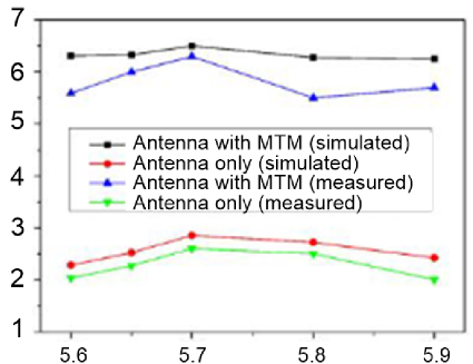
Figure 10: Comparison of gain at 5.7 GHz [69].
Because regular materials do not possess the EM characteristics that metamaterials have, the difficulties outlined previously can be overcome by employing metamaterials [68]. It enhances transfer efficiency and distance by manipulating the electromagnetic waves that are generated by a microwave device [69]. It has been shown that placing a metamaterial over a patch antenna can lower the surface waves, leading to an increase in both the gain and the bandwidth of the antenna [68, 69, 70] as shown in Fig. 10. If the antenna is able to fulfil the requirements of the conventional resonance cavity, then the reflected wave will be able to go through the metamaterial unit cell with the same phase. In turn, the antenna’s gain will improve as a result of this.
Alternately, [71] explored the use of the MTM slab in the MRC-based WPT system a few years ago, which resulted in a significant improvement in the transfer efficiency of the WPT. The MTM slab, which included a near-field WPT system based on MRC, has since been the subject of intensive study employing a wide range of methodologies. Often, one or more MTM slabs are placed between the transmitter and receiver coils. This helps to concentrate the magnetic field on the receiver coil, which in turn results in a large improvement in PTE. In addition to this widely used design, there have been reports of a wide variety of alternative structures.
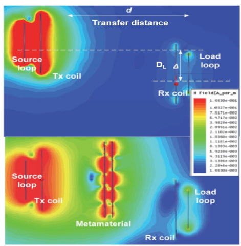
Figure 11: WPT magnetic field distribution [71].
MTM slabs are integrated into WPT systems in a variety of different ways to achieve high PTE. This is accomplished by making use of the one-of-a-kind qualities of MTMs, which include negative refraction and evanescent wave amplification. The magnetic field that is produced by a Tx coil in a WPT system, such as the one shown in Fig. 11, displays its flux lines in a symmetrical pattern around the coil. If the Rx coil is placed in the area where the flux lines from the Tx coil reach then, according to Faraday’s law, the magnetic flux that is crosslinked inside the Rx coil will cause current flows in the Rx coil, resulting in the wireless transmission of power. There is a problem caused by the fact that the magnetic flux created by the Tx coil is not entirely caught by the Rx coil, which results in a low PTE and leakage.
A conceptual schematic representing the MTM-based WPT’s underlying idea can be seen in Fig. 12 (a). Figure 12 (b) illustrates what happens when an MTM slab is placed between Tx and Rx, due to the fact that the MTM slab has a negative refraction index. Since it can concentrate the magnetic field lines directly on the Rx, it can boost power transmission efficiency. Using this idea of MTM-based WPT MTMs, a variety of structures have been examined. These architectures have varying dimensions, and the MTM slabs are located in a variety of different places.
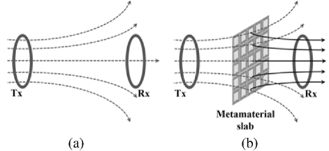
Figure 12: Concept MTM based on WPT.
The effectiveness of MTM structures in WPT applications is significantly influenced by their design and geometry. Liu [72] conducted a study that highlighted the significance of the geometry and structure of the MTM unit in WPT systems. The study introduced a practical model for MTMs. Research showed that the efficacy of the system is significantly impacted by the resonance frequency and quality factor of MTMs, which are determined by their geometric configuration. The study highlighted the importance of precise MTM design for optimal functionality by providing a circuit-based model to predict the performance of MTM-enhanced WPT systems.
Lee [73] conducted an additional study that concentrated on the optimization of low-frequency magnetic MTMs to improve the efficiency of WPT. The research emphasized the critical role of the shape and arrangement of MTM units in attaining the desired magnetic properties, which in turn enhances PTE. The experimental results presented in the study demonstrated a substantial increase in PTE as a result of the implementation of optimized MTM designs, thereby validating the theoretical models that were proposed.
In addition, Li [74] conducted a thorough examination of MTM-based WPT systems, which included a discussion of the efficacy of the systems and the various MTM configurations. The review emphasized that certain MTM geometries, including Swiss roll structures and split-ring resonators, are effective in enhancing PTE and focusing magnetic fields. The authors emphasized the necessity of meticulous MTM design to address the challenges associated with efficiency and alignment in WPT systems.
IV. THE DIFFICULTIES OF MTMS ON WPT SYSTEMS
Integrating MTMs into WPT systems has the potential to greatly boost both the PTE and transmit distance of such systems. The reason for this is that MTMs have properties that contribute to the enhancement, specifically negative refraction and evanescent wave amplification. The introduction of MTMs will unquestionably speed up the development of WPT systems. However, research into the applications of MTM-based WPT systems is still in its preliminary stages. As a result, a number of viewpoints and difficulties associated with MTM-based WPT systems are reviewed here with a view towards future advancement.
Prior to any other consideration, the insertion loss of the MTM slab needs to be minimized as much as possible since PTE is one of the most important merit factors of the WPT system. Despite the inserted MTM slab making the PTE of the WPT systems better, it will invariably suffer from insertion losses in WPT systems that are used in the real world. Chabalko [75] measured Tx and Rx insertion losses with and without MTM slabs and a single-turn resonator. They showed that the PTE of the WPT system may be significantly increased by using a single turn resonator, much more so than by employing an MTM slab, under certain conditions. The insertion loss of the MTM slab is much larger than that of the single turn resonator due to the MTM’s complex construction and the MTM’s non-optimized raw material choices. The previously reported phenomena may be traced back to this root cause.
A superconductor-based MTM slab with minimal conductor loss was shown by Wang [76]. It has been demonstrated that the reduced loss qualities of the superconductor, when combined with the properties of MTMs, may significantly increase the PTE of WPT systems in an efficient manner. Furthermore, it has been hypothesized that such cumbersome structures aren’t necessary to create the negative refraction effect [77]. This is an interesting development. Because a thick substrate might cause an increase in the amount of substrate loss, it is best to utilize an MTM slab with a smaller thickness in order to reduce the amount of insertion loss caused by the MTM slab. Because the MTM slab’s insertion loss has a direct impact on the PTE of the WPT systems, it should be one of the design priorities to minimize it. This is because reducing it has the potential to provide significant improvements to the PTE of the WPT systems, which is why it should be investigated further. When it comes to the final applications, there are other losses that might have an impact on the PTE. Power supplies, amplifiers, resonators, rectifiers, DC-DC converters, loads, and other parts comprise the MRC-based WPT systems as a whole. The end-to-end PTE is significantly impacted by the losses that occur in each step as well as the unpredictability of changes to the parameters (weight, transfer distance, orientation) that occur in WPT environments. Hence, it is vital to enhance the efficiency of each phase in the procedure in MTM-based WPT systems, and the entire WPT system must be able to respond to a broad range of WPT circumstances.
Table 1: Different techniques to enhance WPT system
| Ref. | Type of Antenna | Size of Antenna | Metamaterial Shape | Frequency | Distance | Transfer Efficiency |
| [63] | Single-turn square coils | 100100 mm | 2-sided spiral square coil - 5 turns | 6.78 MHz | 40 cm | 24% |
| [69] | Hexagonal patch | 3525 mm | Hexagon | 5.7-10.3 GHz | 17.53 mm | 90.63% |
| [70] | Microstrip slot | - | Rectangular Sierpinski fractal | 1.38 GHz | - | 34% |
| [73] | Spiral coils | R50 mm | YBCO spiral-coil structure - 13 turns | 58.8 MHz | 20 cm | 13.58% |
| [83] | Circular coils | - | 2-sided square helical coil - 10 turns | 1 MHz | 100 mm | 9% |
| [87] | Loop coil antenna | R20 cm | 2-sided square spiral - 3 turns | 24 MHz | 50 cm | 47% |
| [88] | Loop coil antenna | Tx4.5 cm Rx2 cm | 2-layer square spiral - 13 turns | 4 MHz | 10 cm | 22% |
| [89] | Spiral coils | 1515 cm | Hybrid metamaterial slab design - 14.5 turns | 6.78 MHz | 20 cm | 47% |
| [90] | Spiral coil | R15 cm | Honeycomb hexagon-shaped spiral copper - 9 turns | 6.4 MHz | 20 cm | 51% |
| [91] | Square coil | 1313 cm | 1-sided spiral coil - 5 turns | 13.56 MHz | 30 cm | 36.4% |
| [92] | Square coil | D10 cm | Square spiral coil copper - 11 turns | 13.56 MHz | 30 cm | 13.4% |
| [93] | Circular coil | D40 cm | Circular spiral coil - 3 turns | 6.5 MHz | 100 cm | 15.1% (1-sided), 34.4% (2-sided) |
| [94] | Circular coil | D500 mm | 1-sided square spiral coil - 3 turns | 2.8 MHz | 160 cm | 18.58% |
| [95] | Square coil | 1313 cm | 1-sided square spiral - 5 turns | 13.56 MHz | 30 cm | 41.7% |
| [96] | Circular coil | R20 cm | 1-sided meander line | 27.4 MHz | 20 cm | 10.7% |
Despite the fact that MTMs, because of their one-of-a-kind features, are able to boost the PTE of WPT systems, the development of MTM-based WPT systems for real-world use remains in its infancy. Although WPT system development is being aggressively pursued in a wide range of industries and uses, including the recharging of handheld electronic gadgets, it is clear that this technology has applications in transportation apparatuses or vehicles that run on electricity [78, 79] and medical device replacements [50, 80, 81]. The development of workable MTM-based WPT systems requires substantial investment of time and resources. Most of the observed MTM slabs have a bulky and thick build, which restricts the applications for which these slabs may be used. It is possible that it would not be viable to do so if the additional hefty MTM slab were to be put in the route of the power transmission. The WPT systems’ reduced usefulness and adaptability would make them even less appealing than the more traditional wire charging methods. The following is an outline of the several potential solutions to these problems. To begin, the MTM slab has the potential to be included into the WPT systems. In the near future, research has to be done to determine how best to optimize the location of the MTM slab when it is embedded using this strategy. Second, it can involve incorporating the MTM into intermediary items in a way that does not disrupt the consumers’ experience. In the future, in preparation for real-world deployments, it will be necessary to do more research on MTM-based WPT systems that make use of embedded methods.
Alternatively, one might take into account the current trend of MTM devices. Recent research [82] has focused on active MTMs that may adapt their characteristics in accordance with the information received from the environment. Conventional MTMs, also known as passive MTMs, contain characteristics that are fixed after the device has been manufactured, which restricts the uses of MTM devices. Because they used passive MTMs, the majority of earlier research found that once the MTMs had been constructed, their characteristics could not be altered in any way. Additionally, the MTM slab’s operating frequency will remain constant for the same reason. Several studies in the field of MTM-based WPT systems have focused on active MTMs [83]. An active MTM has been developed by Ranaweera [82] as a method for dynamically field localizing WPT systems. Using this technique, electricity may be sent selectively and under control directly to the desired area (hot zone). Using defect cavities with tunable resonant frequencies that are created on MTM unit cells, it is possible to realize the hot zone. It is possible to increase both PTE and safety by bringing about upgraded fields on the desired region. However, due to the fact that they have been using non-resonant loops for both the Tx and Rx coils, the transmission distance has been restricted.
In addition, there has been no extensive research carried out on transfer distance, which is one of the key characteristics that determine the effectiveness of WPT systems. There is a need for greater investigation into active MTM-based WPT systems, despite the fact that they have proven the active MTM’s value in the field of WPT.
In particular, research that has been done on the active MTMs’ capacity to exhibit negative refraction might be one of the options. With the ability to manipulate the MTM slab’s negative refraction, the WPT’s magnetic fields may be redirected depending on their location. If the Rx coil is not lined with the Tx coil, for example, the active MTM slab’s negative refraction index can be adjusted to re-direct the electric flux to the Rx.
The receiving efficiency in WPT systems is influenced not only by distance but also by the angle at which the receiving coil is positioned relative to the transmitter. Misalignment in the angle affects magnetic coupling, as angular deviation reduces the effective magnetic flux linkage between coils. This misalignment can significantly decrease transfer efficiency, especially in near-field applications like wearable devices and consumer electronics [84]. Prior research highlights that angular deviations lead to reduced magnetic coupling, causing a notable drop in PTE. Because of this, the MTM slab is able to correct the alignment issue. Addressing these angle-related losses, recent studies have explored implementation of MTMs strategically within WPT systems to improve PTE despite angular misalignments. Placing MTM slabs at specific points in the system can enhance electromagnetic wave control, allowing the magnetic field to be effectively redirected and, thus, mitigating efficiency losses due to angular displacement [85]. If the MTM unit cells’ negative refraction property can be altered, it would be possible to obtain a higher degree of flexibility in MTM-based WPT systems, which will lead to a wider range of applications for these systems. It is anticipated that the active MTMs would open up new possibilities for the implementation of MTM-based WPT systems in a variety of settings, including misaligned circumstances and asymmetric WPT environments, among other potential scenarios [86]. These placements can improve PTE by broadening angular tolerance, a significant step forward for stable and efficient WPT across diverse applications.
Table 1 shows a summarization of various techniques for transfer efficiency enhancement. This review aims to provide a quick reference for people engaged in WPT research and shed light on the evolving nature of MTM-based WPT system technologies. Additionally, the prospects and difficulties associated with MTM-based WPT systems have been explored in relation to the development of the technology in general as well as the applications that make use of it.
ACKNOWLEDGMENT
The authors would like to acknowledge the Ministry of Higher Education, Centre for Research and Innovation Management (CRIM) and Universiti Teknikal Malaysia Melaka for supporting this project through FRGS grant numbering FRGS/1/2021/TK0/UTEM/02/52. The authors also would like to extend their sincere gratitude to Multimedia University (MMU) for providing the essential resources and support required to complete this study. Special thanks are due to the Telekom Malaysia Research Grant, project code MMUE220012, for its support, which has been instrumental in facilitating this research.
REFERENCES
[1] S. K. Singh, T. S. Hasarmani, and R. M. Holmukhe, “Wireless transmission of electrical power: Overview of recent research & development,” International Journal of Computer and Electrical Engineering, vol. 4, no. 2, pp. 207-211, 2012.
[2] Qi and Magsafe [Online]. Available: appleinsider.com/articles/21/01/01/qi-and-magsafe—everything-an-iphone-user-needs-to-know-about-wireless-charging
[3] A. Kurs, R. Moffatt, and M. Soljačić, “Simultaneous mid-range power transfer to multiple devices,” Appl. Phys. Lett., vol. 96, no. 4, pp. 2009-2011, 2010.
[4] E. Baghdadi and J. Van Mierlo, “Study of wireless power transfer for electric vehicles,” in Proceedings of the 2018 19th IEEE Mediterranean Electrotechnical Conference (MELECON), Marrakesh, Morocco, pp. 1-6, 2018.
[5] G. Ylmaz and C. Dehollain, Wireless Power Transfer, 4th ed. Amsterdam: Elsevier, 2017.
[6] S. Maslovski, S. Tretyakov, and P. Alitalo, “Near-field enhancement and imaging in double planar polariton-resonant structures,” J. Appl. Phys., vol. 96, no. 3, pp. 1293-1300, 2004.
[7] Z. Chen, B. Guo, Y. Yang, and C. Cheng, “Metamaterials-based enhanced energy harvesting: A review,” Phys. B Condens. Matter, vol. 438, pp. 1-8, 2014.
[8] K. Sun, S. V. Georgakopoulos, and M. P. Nikdast, “An overview of metamaterials and their achievements in wireless power transfer,” Journal of Materials Chemistry C, vol. 6, no. 12, pp. 2925-2943, 2018.
[9] B. Wang, W. Yerazunis, and K. H. Teo, “Wireless power transfer: Metamaterials and array of coupled resonators,” Proc. IEEE, vol. 101, no. 6, pp. 1359-1368, 2013.
[10] C. Yee Yong and K. Fen Chen, “Wireless power transfer technology using resonant technique,” IOP Conf. Ser. Earth Environ. Sci., vol. 268, no. 1, 2019.
[11] D. Stepins, J. Zakis, P. Padmanaban, and D. Deveshkumar Shah, “Suppression of radiated emissions from inductive-resonant wireless power transfer systems by using spread-spectrum technique,” Electron., vol. 11, no. 5, 2022.
[12] B. Esmaeili Jamakani, A. Mosallanejad, E. Afjei, and A. Lahooti Eshkevari, “Investigation of triple quadrature pad for wireless power transfer system of electric vehicles,” IET Electr. Syst. Transp., vol. 11, no. 1, pp. 58-68, 2021.
[13] I. Alhamrouni, M. Iskandar, M. Salem, L. J. Awalin, A. Jusoh, and T. Sutikno, “Application of inductive coupling for wireless power transfer,” Int. J. Power Electron. Drive Syst., vol. 11, no. 3, pp. 1109-1116, 2020.
[14] K. N. Mude, S. S. Williamson, and S. K. Panda, “Comprehensive review and analysis of two-element resonant compensation topologies for wireless inductive power transfer systems,” Chinese Journal of Electrical Engineering, vol. 5, no. 2, pp. 14-31, 2019.
[15] O. D. Oyeleke, S. Thomas, P. Nzerem, and G. Koyunlu, “Design and construction of a prototype wireless power transfer device,” Int. J. Eng. Manuf., vol. 9, no. 2, pp. 16-30, 2019.
[16] M. Carbajal-Retana, J. Hernández-González, and J. R. Rangel-Magdaleno, “Interleaved buck converter for inductive wireless power transfer in DC-DC converters,” Electronics, vol. 9, no. 6, pp. 1-15, 2020.
[17] A. Mahesh, B. Chokkalingam, and L. Mihet-Popa, “Inductive wireless power transfer charging for electric vehicles-A review,” IEEE Access, vol. 9, pp. 137667-137713, 2021.
[18] P. H. Chen, C. Li, Z. Dong, and M. Priestley, “Inductive power transfer battery charger with IR-based closed-loop control,” Energies, vol. 15, no. 21, 2022.
[19] A. Ragab, M. I. Marei, M. Mokhtar, and A. Abdelsattar, “Design and performance evaluation of a PV interface system based on inductive power transfer,” Int. J. Power Electron. Drive Syst., vol. 12, no. 1, pp. 364-373, 2021.
[20] V. Shevchenko, M. Khomenko, I. Kondratenko, O. Husev, and B. Pakhaliuk, “Experimental comparison of designed inductance coils for wireless power transfer,” Electr. Control Commun. Eng., vol. 16, no. 2, pp. 102-109, 2020.
[21] Electrice, “Actualităţi şi perspective în domeniul maşinilor electrice,” Actualităţi şi Perspective în Domeniul Maşinilor Electrice, pp. 66-75, 2005.
[22] M. H. Misran, M. A. M. Said, M. A. Othman, R. A. Manap, S. Suhaimi, and N. I. Hassan, “A systematic optimization procedure of antenna miniaturization for efficient wireless energy transfer,” International Journal of Electrical and Computer Engineering (IJECE), vol. 9, no. 4, pp. 3159-3166, Aug. 2019.
[23] Y. Yamada, T. Imura, and Y. Hori, “Theorizing a simple ferrite cored coil using image coils in wireless power transfer,” IEEE Access, vol. 11, pp. 8065-8072, 2023.
[24] A. F. Abdul Aziz, M. F. Romlie, and Z. Baharudin, “Review of inductively coupled power transfer for electric vehicle charging,” IET Power Electron., vol. 12, no. 14, 2019.
[25] M. Rehman, P. Nallagownden, and Z. Baharudin, “Efficiency investigation of SS and SP compensation topologies for wireless power transfer,” Int. J. Power Electron. Drive Syst., vol. 10, no. 4, pp. 2157-2164, 2019.
[26] N. T. Diep, N. K. Trung, and T. T. Minh, “Wireless power transfer system design for electric vehicle dynamic charging application,” Int. J. Power Electron. Drive Syst., vol. 11, no. 3, pp. 1468-1480, 2020.
[27] J. Lee, M. Y. Kim, and S. H. Lee, “Novel transformerless multilevel inductive power transfer system,” IEEE Access, vol. 10, pp. 55565-55573, 2022.
[28] Q. T. Vo, Q. T. Duong, and M. Okada, “Load-independent voltage control for multiple-receiver inductive power transfer systems,” IEEE Access, vol. 7, pp. 139450-139461, 2019.
[29] D. M. Roberts, A. P. Clements, R. McDonald, J. S. Bobowski, and T. Johnson, “Mid-range wireless power transfer at 100 MHz using magnetically coupled loop-gap resonators,” IEEE Trans. Microw. Theory Tech., vol. 69, no. 7, pp. 3510-3527, 2021.
[30] J. N. Wandinger, D. M. Roberts, J. S. Bobowski, and T. Johnson, “Inductive power transfer through saltwater,” in 2021 13th Int. Conf. Electromagn. Wave Interact. with Water Moist Subst. ISEMA, vol. 2, no. 4, 2021.
[31] C. Y. Liu, G. Bin Wang, C. C. Wu, E. Y. Chang, S. Cheng, and W. H. Chieng, “Derivation of the resonance mechanism for wireless power transfer using class-e amplifier,” Energies, vol. 14, no. 3, 2021.
[32] B. A. Rayan, U. Subramaniam, and S. Balamurugan, “Wireless power transfer in electric vehicles: A review on compensation topologies, coil structures, and safety aspects,” Energies, vol. 16, no. 7, 2023.
[33] Z. Despotovic, D. Reljic, V. Vasic, and D. Oros, “Steady-state multiple parameters estimation of the inductive power transfer system,” IEEE Access, vol. 10, pp. 46878-46894, 2022.
[34] H. Sadeghi Gougheri and M. Kiani, “An inductive voltage-/current-mode integrated power management with seamless mode transition and energy recycling,” IEEE Journal of Solid-State Circuits, vol. 54, no. 3, pp. 874-884, Mar. 2019.
[35] C. Rong, W. Li, Z. Zhou, C. Zhu, and Z. Deng, “A critical review of metamaterial in wireless power transfer system,” IET Power Electronics, vol. 14, no. 9, pp. 1541-1559, 2021.
[36] R. Jyosthna, R. A. Sunny, A. A. Jugale, and M. R. Ahmed, “Microstrip patch antenna design for space applications,” in Proceedings of the 2020 International Conference on Communication and Signal Processing (ICCSP), Chennai, India, pp. 406-410, 2020.
[37] M. H. Misran, M. A. M. Said, M. A. Othman, R. Abd Manap, S. Suhaimi, and N. I. Hassan, “DGS based CP antenna for 5G communication with harmonic,” International Journal of Integrated Engineering, vol. 16, no. 1, pp. 301-311, 2024.
[38] D. Ahn and S. Hong, “A study on magnetic field repeater in wireless power transfer,” IEEE Trans. Ind. Electron., vol. 60, no. 1, pp. 360-371, 2013.
[39] M. Liu, M. Fu, Y. Wang, and C. Ma, “Battery cell equalization via megahertz multiple-receiver wireless power transfer,” IEEE Trans. Power Electron., vol. 33, no. 5, pp. 4135-4144, 2018.
[40] Z. Dong, S. Liu, X. Li, Z. Xu, and L. Yang, “A novel long-distance wireless power transfer system with constant current output based on domino-resonator,” IEEE J. Emerg. Sel. Top. Power Electron., vol. 9, no. 2, pp. 2343-2355, 2021.
[41] W. X. Zhong, C. K. Lee, and S. Y. R. Hui, “Wireless power domino-resonator systems with noncoaxial axes and circular structures,” IEEE Trans. Power Electron., vol. 27, no. 11, pp. 4750-4762, 2012.
[42] C. Cheng, Z. Zhou, W. Li, C. Zhu, and Z. Deng, “A multi-load wireless power transfer system with series-parallel-series compensation,” IEEE Transactions on Power Electronics, vol. 34, no. 8, pp. 7126-7130, 2019.
[43] Y. H. Kim, S. Y. Kang, S. Cheon, M. L. Lee, J. M. Lee, and T. Zyung, “Optimization of wireless power transmission through resonant coupling,” in SPEEDAM 2010 Int. Symp. Power Electron. Electr. Drives, Autom. Motion, pp. 1069-1073, 2010.
[44] Q. Ke, W. Luo, G. Yan, and K. Yang, “Analytical model and optimized design of power transmitting coil for inductively coupled endoscope robot,” IEEE Trans. Biomed. Eng., vol. 63, no. 4, pp. 694-706, 2016.
[45] A. L. F. Stein, P. A. Kyaw, and C. R. Sullivan, “Wireless power transfer utilizing a high-Q self-resonant structure,” IEEE Trans. Power Electron., vol. 34, no. 7, pp. 6722-6735, 2019.
[46] J. O. Mur-Miranda, J. H. Lang, K. A. Gilhousen, and J. P. Florance, “Wireless power transfer using weakly coupled magnetostatic resonators,” in Proceedings of the 2010 IEEE Energy Conversion Congress and Exposition (ECCE), pp. 4179-4186, 2010.
[47] J. H. Park, B. C. Park, J. H. Lee, Y. H. Ryu, E. S. Park, and S. W. Kwon, “Optimum frequency of high Q-factor resonator for magnetic resonance coupling,” in Proceedings of the 41st European Microwave Conference (EuMC), pp. 61-63, 2011.
[48] Y. Kawamura and M. Shoyama, “Wireless power transmission using LC cancellation,” in 2013 IEEE ECCE Asia Downunder 5th IEEE Annu. Int. Energy Convers. Congr. Exhib. IEEE ECCE Asia 2013, pp. 1041-1045, 2013.
[49] K. Tashiro, H. Wakiwaka, S. I. Inoue, and Y. Uchiyama, “Energy harvesting of magnetic power-line noise,” IEEE Trans. Magn., vol. 47, no. 10, pp. 4441-4444, 2011.
[50] B. H. Soong, Y. L. Sum, W. Liu, and S. Ramachandran, “Characterizing wire wound inductor coils for optimized wireless power transfer,” in IEEE/ASME Int. Conf. Adv. Intell. Mechatronics (AIM), pp. 469-474, 2009.
[51] M. Takato, T. Yamada, T. Nishikawa, and K. Saito, “Multilayer ceramic coil for wireless power transfer system by photo resist film process,” in Proceedings of the 2014 International Conference on Electronics Packaging (ICEP), pp. 326-331, 2014.
[52] N. S. Artan, R. C. Patel, C. Ning, and H. J. Chao, “High-efficiency wireless power delivery for medical implants using hybrid coils,” in Proc. Annu. Int. Conf. IEEE Eng. Med. Biol. Soc. (EMBS), no. 3, pp. 1683-1686, 2012.
[53] C. Zhu, K. Liu, C. Yu, R. Ma, and H. Cheng, “Simulation and experimental analysis on wireless energy transfer based on magnetic resonances,” in 2008 IEEE Veh. Power Propuls. Conf. (VPPC) 2008, pp. 18-21, 2008.
[54] S. A. Chowdhury, S. Kim, S. Kim, J. Moon, I. Cho, and D. Ahn, “Automatic tuning resonant capacitor to fix the bidirectional detuning with ZVS in wireless power transfer,” IEEE Transactions on Industrial Electronics, vol. 71, no. 6, pp. 5683-5692, June 2024.
[55] G. Giovannetti and D. De Marchi, “Capacitors quality effect in magnetic resonance radiofrequency coils,” J. Med. Biol. Eng., vol. 37, pp. 639-643, 2017.
[56] M. I. A. Abdel Maksoud, R. A. Fahim, A. E. Shalan, M. A. Abd Elkodous, M. A. Olojede, M. M. Allam, and H. O. M. Ibrahim, “Advanced materials and technologies for supercapacitors used in energy conversion and storage: A review,” Environmental Chemistry Letters, vol. 19, pp. 375-439, 2021.
[57] A. Boardman, “Pioneers in metamaterials: John Pendry and Victor Veselago,” Journal of Optics, vol. 13, no. 2, p. 020401, 2010.
[58] K. Sun, J. Wang, Y. Ma, Z. Wu, and Y. Zhang, “Random copper/yttrium iron garnet composites with tunable negative electromagnetic parameters prepared by in situ synthesis,” RSC Advances, vol. 5, no. 75, pp. 61155-61160, 2015.
[59] N. Engheta and R. W. Ziolkowski, “A positive future for double-negative metamaterials,” IEEE Trans. Microw. Theory Tech., vol. 53, no. 4 II, pp. 1535-1555, 2005.
[60] J. Shin, A. Akyurtlu, M. Deshpande, and R. W. Ziolkowski, “Comments on ‘design, fabrication, and testing of double negative metamaterials’,” IEEE Trans. Antennas Propag., vol. 53, no. 2, pp. 891-892, 2005.
[61] S. White, “The transmission of electrical energy without wires as a means for furthering peace,” Electrical World and Engineer, Mar. 5, 1904.
[62] A. A. Eteng, S. K. A. Rahim, C. Y. Leow, S. Jayaprakasam, and B. W. Chew, “Low-power near-field magnetic wireless energy transfer links: A review of architectures and design approaches,” Renew. Sustain. Energy Rev., vol. 77, pp. 486-505, Apr. 2017.
[63] W. Li, P. Wang, C. Yao, Y. Zhang, and H. Tang, “Experimental investigation of 1D, 2D, and 3D metamaterials for efficiency enhancement in a 6.78MHz wireless power transfer system,” in 2016 IEEE Wirel. Power Transf. Conf. (WPTC) 2016, pp. 19-22, 2016.
[64] M. S. Yusri, M. H. Misran, N. Yusop, M. A. M. Said, M. A. Othman, and S. Suhaimi, “Transfer efficiency enhancement on wireless power transfer using metamaterial,” in 2023 International Conference on Information Technology (ICIT), Amman, Jordan, pp. 724-729, 2023.
[65] J. Park, Y. Tak, Y. Kim, Y. Kim, and S. Nam, “Investigation of adaptive matching methods for near-field wireless power transfer,” IEEE Trans. Antennas Propag., vol. 59, no. 5, pp. 1769-1773, 2011.
[66] T. C. Beh, M. Kato, T. Imura, S. Oh, and Y. Hori, “Automated impedance matching system for robust wireless power transfer via magnetic resonance coupling,” IEEE Trans. Ind. Electron., vol. 60, no. 9, pp. 3689-3698, 2013.
[67] F. Zhang, S. A. Hackworth, W. Fu, C. Li, Z. Mao, and M. Sun, “Relay effect of wireless power transfer using strongly coupled magnetic resonances,” IEEE Trans. Magn., vol. 47, no. 5, pp. 1478-1481, 2011.
[68] A. K. Singh, M. P. Abegaonkar, and S. K. Koul, “High-gain and high-aperture-efficiency cavity resonator antenna using metamaterial superstrate,” IEEE Antennas Wirel. Propag. Lett., vol. 16, pp. 2388-2391, 2017.
[69] N. Rajak, N. Chattoraj, and R. Mark, “Metamaterial cell inspired high gain multiband antenna for wireless applications,” AEU Int. J. Electron. Commun., vol. 109, pp. 23-30, 2019.
[70] G. Varamini, A. Keshtkar, N. Daryasafar, and M. Naser-Moghadasi, “Microstrip Sierpinski fractal carpet for slot antenna with metamaterial loads for dual-band wireless application,” AEU Int. J. Electron. Commun., vol. 84, pp. 93-99, Oct. 2018.
[71] B. Wang, T. Nishino, and K. H. Teo, “Wireless power transmission efficiency enhancement with metamaterials,” in 2010 IEEE Int. Conf. Wirel. Inf. Technol. Syst. (ICWITS 2010), no. 1, pp. 2-5,2010.
[72] J. Liu, Z. Gong, S. Yang, H. Sun, and J. Zhou, “Practical model for metamaterials in wireless power transfer systems,” Appl. Sci., vol. 10, p. 8506, 2020.
[73] W. Lee and Y.-K. Yoon, “Wireless power transfer systems using metamaterials: A review,” IEEE Access, vol. 8, pp. 147930-147947, 2020.
[74] W. Li, F. Yu, X. Rong, and H. Qin, “Optimization of low-frequency magnetic metamaterials for efficiency improvement in magnetically coupled resonant wireless power transfer systems,” IEEE Access, vol. 10, pp. 125445-125457,2022.
[75] M. J. Chabalko, J. Besnoff, and D. S. Ricketts, “Magnetic field enhancement in wireless power with metamaterials and magnetic resonant couplers,” IEEE Antennas Wirel. Propag. Lett., vol. 15, pp. 452-455, 2016.
[76] X. Wang, Y. Wang, Y. Hu, Y. He, and Z. Yan, “Analysis of wireless power transfer using superconducting metamaterials,” IEEE Trans. Appl. Supercond., vol. 29, no. 2, 2019.
[77] D. R. Smith, D. Schurig, J. J. Mock, P. Kolinko, and P. Rye, “Partial focusing of radiation by a slab of indefinite media,” Appl. Phys. Lett., vol. 84, no. 13, pp. 2244-2246, 2004.
[78] K. A. Cota, P. A. Gray, M. Pathmanathan, and P. W. Lehn, “An approach for selecting compensation capacitances in resonance-based EV wireless power transfer systems with switched capacitors,” IEEE Trans. Transp. Electrif., vol. 5, no. 4, pp. 1004-1014, 2019.
[79] Y. Liu, U. K. Madawala, R. Mai, and Z. He, “Zero-phase-angle controlled bidirectional wireless EV charging systems for large coil misalignments,” IEEE Trans. Power Electron., vol. 35, no. 5, pp. 5343-5353, 2020.
[80] K. Zhang, C. Liu, Z. H. Jiang, Y. Zhang, X. Liu, H. Guo, and X. Yang, “Near-field wireless power transfer to deep-tissue implants for biomedical applications,” IEEE Transactions on Antennas and Propagation, vol. 68, no. 2, pp. 1098-1106, 2020.
[81] M. Song, K. Baryshnikova, A. Markvart, P. Belov, E. Nenasheva, C. Simovski, and P. Kapitanova, “Smart table based on a metasurface for wireless power transfer,” Physical Review Applied, vol. 11, no. 5, p. 054046, 2019.
[82] A. L. A. K. Ranaweera, T. S. Pham, H. N. Bui, V. Ngo, and J. W. Lee, “An active metasurface for field-localizing wireless power transfer using dynamically reconfigurable cavities,” Sci. Rep., vol. 9, no. 1, pp. 1-12, 2019.
[83] M. A. Badwey, N. H. Abbasy, and G. M. Eldallal, “An efficient design of LC-compensated hybrid wireless power transfer system for electric vehicle charging applications,” Alexandria Eng. J., vol. 61, no. 8, pp. 6565-6580, 2022.
[84] S. Wang, C. Jiang, X. Tao, F. Chen, C. Rong, C. Lu, Y. Zeng, X. Liu, R. Liu, B. Wei, and M. Liu, “Enhancing the stability of medium range and misalignment wireless power transfer system by negative magnetic metamaterials,” Materials, vol. 13, 2020.
[85] J. Wang, R. Chen, C. Cai, J. Zhang, and C. Wang, “An onboard magnetic integration-based WPT system for UAV misalignment-tolerant charging with constant current output,” IEEE Transactions on Transportation Electrification, vol. 9, pp. 1973-1984, 2023.
[86] Z. Yuan, Q. Yang, X. Zhang, R. Wang, X. Ma, C. Cai, P. Zhang, and H. Lin, “A power-enhancing complementary coupling integration strategy for misalignment-tolerant WPT systems,” IEEE Transactions on Power Electronics, vol. 38, pp. 14689-14701, 2023.
[87] B. Wang, K. H. Teo, T. Nishino, W. Yerazunis, J. Barnwell, and J. Zhang, “Experiments on wireless power transfer with metamaterials,” Appl. Phys. Lett., vol. 98, no. 25, pp. 1-4, 2011.
[88] Y. Z. Cheng, J. Jin, W. L. Li, J. F. Chen, B. Wang, and R. Z. Gong, “Indefinite-permeability metamaterial lens with finite size for miniaturized wireless power transfer system,” AEU Int. J. Electron. Commun., vol. 70, no. 9, pp. 1282-1287, 2016.
[89] Y. Cho, S. Lee, J. Lee, and J. Lee, “Hybrid metamaterial with zero and negative permeability to enhance efficiency in wireless power transfer system,” in Proceedings of the 2016 IEEE Wireless Power Transfer Conference (WPTC), Aveiro, Portugal, pp. 1-3, 2016.
[90] W. Xin, C. C. Mi, F. He, M. Jiang, and D. Hua, “Investigation of negative permeability metamaterials for wireless power transfer,” AIP Adv., vol. 7, no. 11, 2017.
[91] J. Chen and H. Tan, “Metamaterial for wireless power transfer system at 13.56 MHz with coil misalignment,” in Proc. 2017 7th IEEE Int. Symp. Microwave, Antenna, Propagation, EMC Technol. (MAPE 2017), pp. 313-317, 2017.
[92] C. Lu, X. Huang, C. Rong, Z. Hu, J. Chen, X. Tao, S. Wang, B. Wei, and M. Liu, “Shielding the magnetic field of wireless power transfer system using zero-permeability metamaterial,” The Journal of Engineering, vol. 2019, no. 16, pp. 1812-1815, 2019.
[93] A. L. A. K. Ranaweera, T. P. Duong, and J. W. Lee, “Experimental investigation of compact metamaterial for high efficiency mid-range wireless power transfer applications,” J. Appl. Phys., vol. 116, no. 4, 2014.
[94] C. Rong, X. Tao, C. Lu, Z. Hu, X. Huang, Y. Zeng, and M. Liu, “Analysis and optimized design of metamaterials for mid-range wireless power transfer using a Class-E RF power amplifier,” Appl. Sci., vol. 9, no. 1, p. 26, 2018.
[95] J. Chen, X. Liu, Y. Zhao, and Y. Sun, “Metamaterial-based high-efficiency wireless power transfer system at 13.56 MHz for low power applications,” Progress in Electromagnetics Research B, vol. 72, pp. 17-30, 2017.
[96] T. Shaw, A. Roy, and D. Mitra, “Efficiency enhancement of wireless power transfer system using MNZ metamaterials,” Prog. Electromagn. Res. C, vol. 68, pp. 11-19, Aug. 2016.
BIOGRAPHIES

Muhammad Sukriyllah Yusri graduated from Universiti Malaysia Terengganu where he received his B.Sc. Applied Science majoring in Physics Electronic and Instrumentation. He currently is pursuing the M.Sc. degree in Electronic Engineering from Universiti Teknikal Malaysia Melaka. His current research interests focus on enhancing the inductive wireless power transfer using metamaterial. He is also interested in electronic circuit design, embedded systems, and wireless communication technologies.

Mohamad Harris Misran was born in Johor, Malaysia. He obtained his degree in B.Eng. in Electronics Engineering (Telecommunication) from University of Surrey, UK, in 2006 and M.Eng. in Engineering (Telecommunication) in 2008 from University of Wollongong, Australia. He is Ph.D. holder in Electrical Engineering from Universiti Teknologi Malaysia (UTM), Johor, Malaysia. Currently he is working with UTeM Melaka since 2006 and focusing on RF and microwave circuits, devices and also wireless power transfer.

Tan Kim Geok received the B.E., M.E., and PhD. degrees in electrical engineering from University of Technology Malaysia, in 1995, 1997, and 2000, respectively. He was Senior RD engineer in EPCOS Singapore in 2000. In 2001-2003, he joined DoCoMo Euro-Labs in Munich, Germany. He is currently a member of the academic staff at Multimedia University. His research interests include radio propagation for outdoor and indoor, RFID, multi-user detection technique for multicarrier technologies, and A-GPS.

Norbayah Yusop received the B.Sc. degree in telecommunication electronics from the Universiti Teknikal Malaysia Melaka (UTeM), the M.Sc. degree in telecommunication and information engineering from the Universiti Teknologi Mara (UiTM) and the Ph.D. degree in space science from the Universiti Kebangsaan Malaysia (UKM). She was attached to the Fakulti Kejuruteraan Elektronik dan Kejuruteraan Komputer (FKEKK) as a tutor in 2009. She completed her Ph.D. studies in 2019. Her research interests include lightning physic, microwave propagation and telecommunication engineering.

Maizatul Alice Meor Saidreceived the B.Eng. in Electronics Engineering (Telecommunication) from University of Surrey, UK, in 2006. She obtained M.Eng. in Master of Engineering (Telecommunication) in 2009 from University of Wollongong, Australia. Currently, she is a Ph.D. holder at the Universiti Teknikal Malaysia Melaka (UTeM), Melaka, Malaysia. Her research areas include RF energy harvesting, resonators, amplifiers and antennas and microwave sensors.

Azahari Salleh received both first and master’s degree from Universiti Teknologi Malaysia, in Electrical Electronic Engineering 2003 and 2008. He joined UTeM in 2005 and currently pursuing Ph.D. in microwave imaging. His research interest on microwave device and imaging system design.

Sharul Kamal Abdul Rahim received his first degree from University of Tennessee, USA, majoring in Electrical Engineering, graduating in 1996, M.Sc. in Engineering (Communication Engineering) from Universiti Teknologi Malaysia (UTM) in 2001, and Ph.D. in Wireless Communication System from University of Birmingham, UK, in 2007. Currently, he is an Associate Professor at Wireless Communication Centre, Faculty of Electrical Engineering, UTM. His research interest is smart antenna communication systems.
ACES JOURNAL, Vol. 40, No. 3, 237–252
doi: 10.13052/2025.ACES.J.400308
© 2025 River Publishers