Wideband Low-Profile Fabry-Perot Cavity Antenna with Metasurface
Xueyan Song, Ang Dong, XuPing Li, YunQi Zhang, Haoyuan Lin, Hailong Yang, and Yapeng Li
School of Electronic Engineering
Xi’an University of Posts & Telecommunications, Xi’an 710121, China
xysong65@xupt.edu.cn, 1361580350@qq.com, lixuping@163.com, johnny_5@126.com,
2806198782@qq.com, liyapengedu@163.com, yanghl68@163.com
Submitted On: January 5, 2024; Accepted On: April 1, 2024
ABSTRACT
A novel Fabry-Perot cavity (FPC) antenna with metasurface is presented, which can achieve broad bandwidth and low profile. Traditional FPC antennas, with rectangular microstrip antennas as feeds, have limited impedance bandwidth and struggle to make a compromise in the gain bandwidth and maximum gain value. To obtain wide bandwidth, the FPC antenna proposed in this paper utilizes a feed antenna loaded with parasitic patches. To widen impedance bandwidth and gain bandwidth and reduce the profile, a positive phase gradient partially reflective surface (PRS) and an artificial magnetic conductor (AMC) are located above and below the feed antenna, respectively. The phase property of the PRS and AMC also brings in a more smooth gain value curve. To further increase gain values, four metal reflector plates are located around the proposed antenna. The overall dimension of the antenna is 2.52.50.25 ( is the free space wavelength at 7.5 GHz). Simulated results show that the resonant cavity antenna proposed in this letter exhibits an impedance bandwidth of 13.3% (7–8 GHz) and a 3 dB gain bandwidth of 14.3% (7.02–8.10 GHz). The maximum gain in the whole operating band is 14.5 dBi. The measured results are in good agreement with the simulated ones.
Index Terms: Fabry-Perot cavity, high gain, low-profile, wideband.
I. INTRODUCTION
Developments of communication technology bring in appearance of numerous high-gain antennas, in which Fabry-Perot cavity (FPC) antennas have drawn plenty of interest from academics [1–3]. According to operation mechanism of resonant cavity antennas, the height of most Fabry-Perot antennas is at least a half wavelength [4, 5]. In traditional Fabry-Perot antennas, perfect electric conductors (PEC) are utilized as ground, which results in high profile [6]. To meet the requirement of miniaturization of antennas, it is essential to research how to reduce the profile while maintaining the bandwidth.
Because of in-phase properties, an artificial magnetic conductor (AMC), when utilized as ground of the antenna, can effectively reduce the profile compared with PEC. Consequently, a number of FPC antennas with AMC ground have been presented [7, 8]. In [7], a miniaturized Fabry-Perot antenna is proposed which achieves a high gain of 12.4 dBi by adopting an AMC ground. The bandwidth is 6.4%. To achieve higher gain value, a novel FPC antenna is designed in [8], which has a profile of one-eighth wavelength and a maximum gain of 16.27 dBi, while the bandwidth is required to be widened. Similarly, antennas with AMC surfaces in [9–12] achieve low profiles. However, both the impedance bandwidth and gain bandwidth are need to be broadened due to the phase effect of AMC surface.
In order to achieve wider bandwidth and lower profile, a novel FPC antenna is proposed in this paper. For simplicity, a rectangular microstrip antenna is used as the feed antenna. To obtain broad gain bandwidth, a partially reflective surface is designed above the feed antenna. Moreover, the profile of the antenna can be reduced to a quarter wavelength by loading an AMC ground above the feed antenna. To further increase the maximum gain value, four metal reflector plates are placed around the antenna, and the maximum gain reaches 14.5 dBi. Simulated results show that the impedance bandwidth is 13.3%, and the 3 dB gain bandwidth is 14.3%. In summary, the designed antenna in this paper can obtain a wider gain bandwidth and a quarter wavelength profile simultaneously. Moreover, by loading the reflective wall without increasing the longitudinal size, the gain values of the designed antenna is further increased.
II. ANTENNA DESIGN
A. Antenna configuration
Figure 1 illustrates the proposed configuration, which is etched on 2-mm-thick substrates (=2.2, tan=0.001). A microstrip patch antenna loaded with a 5-mm-thick parasitic patches is designed and utilized as feed antenna. At a height of 10 millimeters above the antenna is located a partially reflective surface, which consists of 1010 units. On the upper layer of the unit is a circular patch and on the lower layer is a cross patch. An AMC structure with rectangular unit is located at the bottom of the feed antenna, which is surrounded by four metal reflector plates. Dimensions (unit: mm): S=20, S=10, P=16, P=13.2, P=12.1, P=5, P=12, X=7.8, X=1, X=2, X=0.6, and X=8.
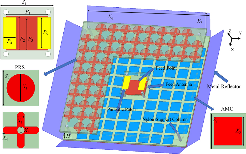
Figure 1: 3D geometry of proposed antenna.
B. Working mechanism
The feed antenna, as shown in Fig. 2 (b), is a rectangular microstrip antenna loaded with parasitic patches. Compared with the antenna in Fig. 2 (a), the feed antenna generates a new resonance in high frequency band when loaded with parasitic patches, which exhibit a wider impedance bandwidth. Figure 3 presents S of the feed antenna with and without parasitic patches. It can be seen that the impedance bandwidth of the microstrip antenna broadens from 6.6% (6.75–7.21 GHz) to 12.8% (6.85–7.79 GHz) when loaded with parasitic patches. Figure 4 shows the electric field distribution at 7 and 7.7 GHz of the feed antenna with parasitic patches. It can be found that the microstrip antenna mainly generates resonances at 7 GHz, and the parasitic patches are primary resonant at 7.7 GHz. When loaded with parasitic patches, multiple resonances can be generated, which broadens the bandwidth of the feed antenna.
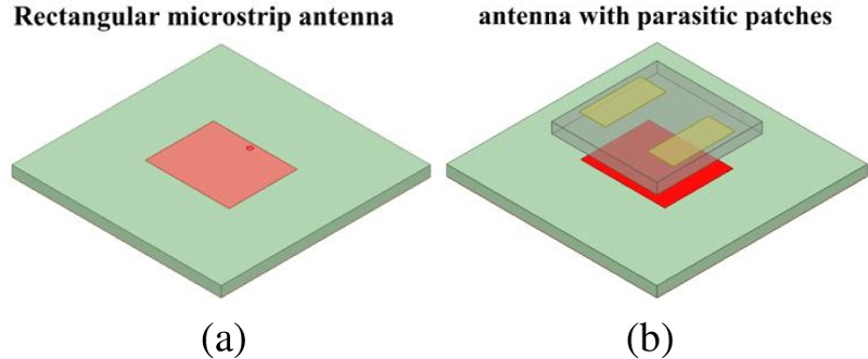
Figure 2: Schematic diagram of feed source antenna structure.
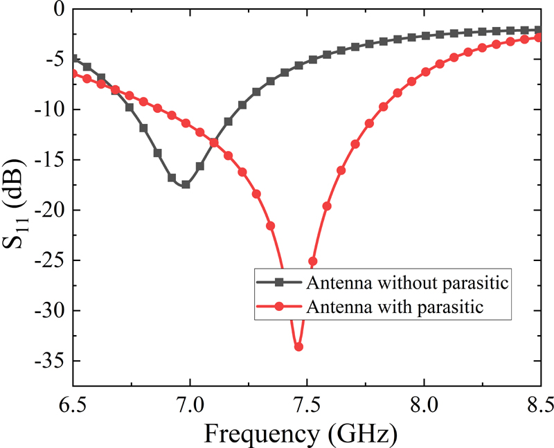
Figure 3: S of the feed antenna with and without parasitic patches.
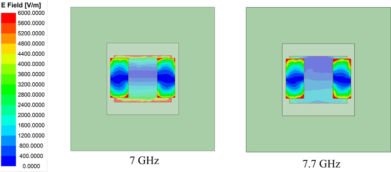
Figure 4: Electric field distribution of the feed antenna.
According to FPCA theory, the response of the resonant cavity antenna satisfies equations (1) and (2) [12, 13], where is the reflection magnitude of the partially reflective surface (PRS):
| (1) |
| (2) |
where Hc is the profile height of the antenna in a high-gain resonant state. When the operation frequency is given, the parameter Hc has an effect on the phase response of the upper and lower layers of metasurfaces. D is the directivity of antennas. Generally, the larger the reflection coefficient of reflective surfaces, the higher the directivity, which will also increase dimension of antennas simultaneously. Therefore, there should be a compromise between the dimension and the directivity in the design of antennas. The proposed antenna is designed aiming to form a resonant cavity and obtain high gain by adopting a partially reflecting surface and anAMC.
By designing a partially reflective surface with a positive phase response, the resonant state expressed in equation (1) can be maintained with wider bandwidth. Additionally, the AMC surface is designed to achieve low profile because of in-phase reflective phase. A square patch is used as the AMC unit, which is because the square unit exhibits an excellent in-phase reflection bandwidth and is easily adjusted to generate a resonant in the band expressed in equation (1).
III. SIMULATED RESULTS
The performances are simulated by using ANSYS HFSS Floquet-port model. Figures 5 (a) and (b) show the phase response plot of AMC and the phase and magnitude response plot of partially reflective surface, respectively. From Fig. 5 (a), the phase values of AMC are greater than the theoretical ones, which is designed to ensure a wide phase margin when it is summed with that of the partially reflective surface to satisfy the resonant state in equation (1).
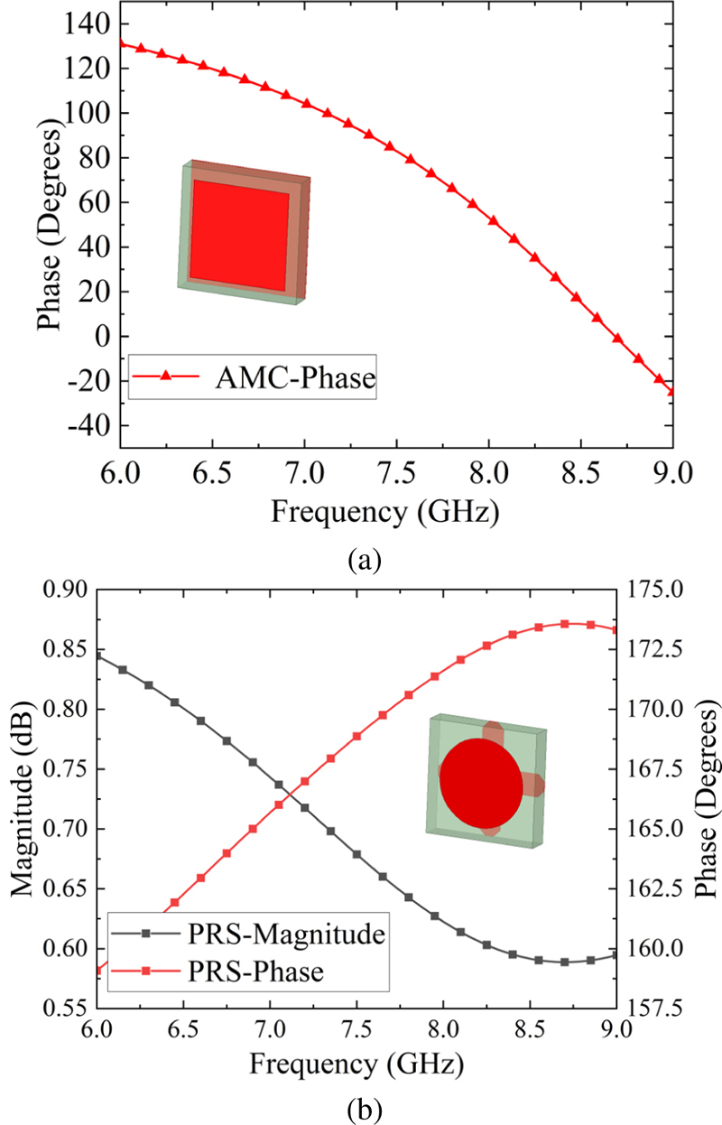
Figure 5: (a) Phase response of AMC and (b) phase and magnitude response of PRS.
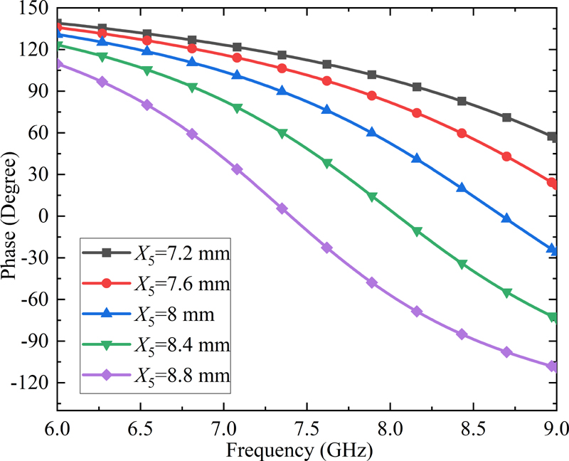
Figure 6: Phase response of AMC varies with X.
A square patch is chosen as AMC unit because that is a simple structure, making it convenient to adjust the phase values. Figure 6 shows the phase value curves with different values of parameter X. As X increases, the phase curves of AMC move towards the low frequency band. X is the unit dimension of the AMC, and the resonance frequency decreases as X increases. To obtain a required phase, the value of X needs to be adjusted.
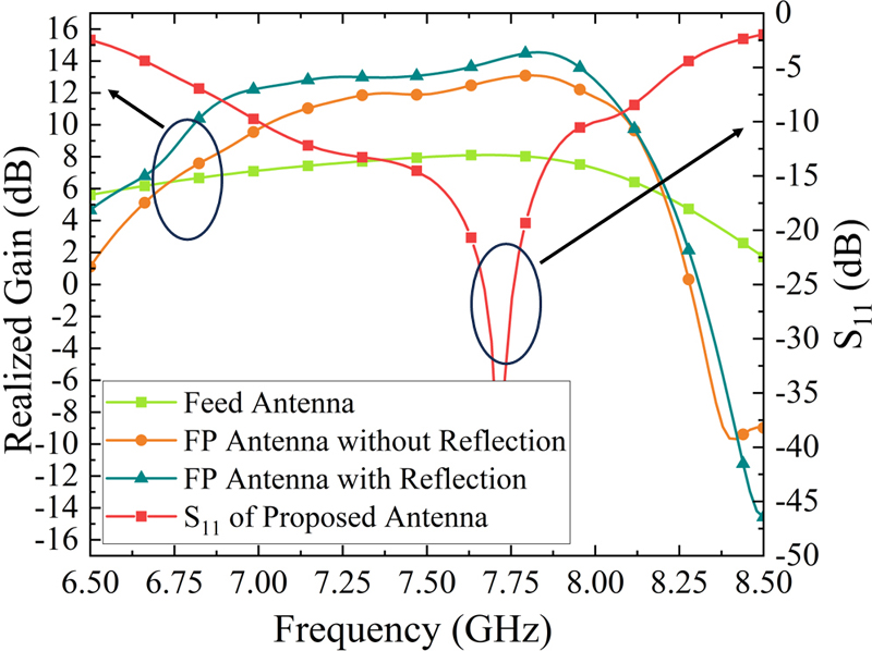
Figure 7: Simulated realized gain and S.
The simulated S and gain of the proposed antenna in different situations are shown in Fig. 7. The simulated impedance bandwidth is from 7 to 8 GHz, and the 3 dB gain bandwidth ranges from 7.02 to 8.10 GHz. It can be seen that the gain bandwidth of the antenna basically coincides with the impedance bandwidth. The FP antenna without reflection has 4 dB higher gain values than that of the feed antenna. Moreover, after added reflection, the gain values of the proposed antenna are increased by 2 dB. Ultimately, the final designed antenna achieves an axial maximum gain value of 14.5 dBi, which is 6.4 dB higher than that of the feed antenna.
IV. EXPERIMENTAL RESULTS
To validate the simulations, the designed antenna is fabricated and measured as shown in Fig. 8. The reflection coefficients are measured by a Keysight E5063A network analyzer. Figure 9 depicts the simulated and measured S. The measured S is from 6.91 to 7.81 GHz, which agrees with the simulated ones (7 to 8 GHz) except for a small offset. The small difference between the measured and the simulated results is mainly caused by fabrication and measured error. The radiation pattern is measured in the microwave laboratory. Figure 10 illustrates the 2D radiation pattern at 7.5 GHz in xoz and yoz planes, from which it can be demonstrated that the measured radiation patterns agree well with the simulated ones. The presented antenna exhibits good radiation directivity, and the cross polarization is less than 30 dB in the main radiation direction.
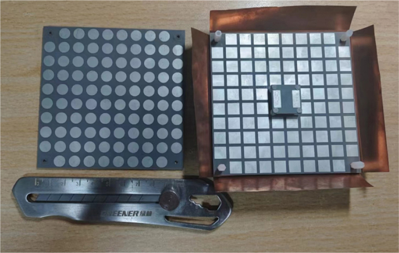
Figure 8: The proposed antenna prototype.
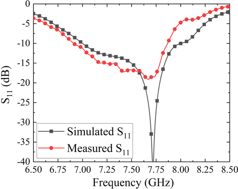
Figure 9: Measured and simulated S.
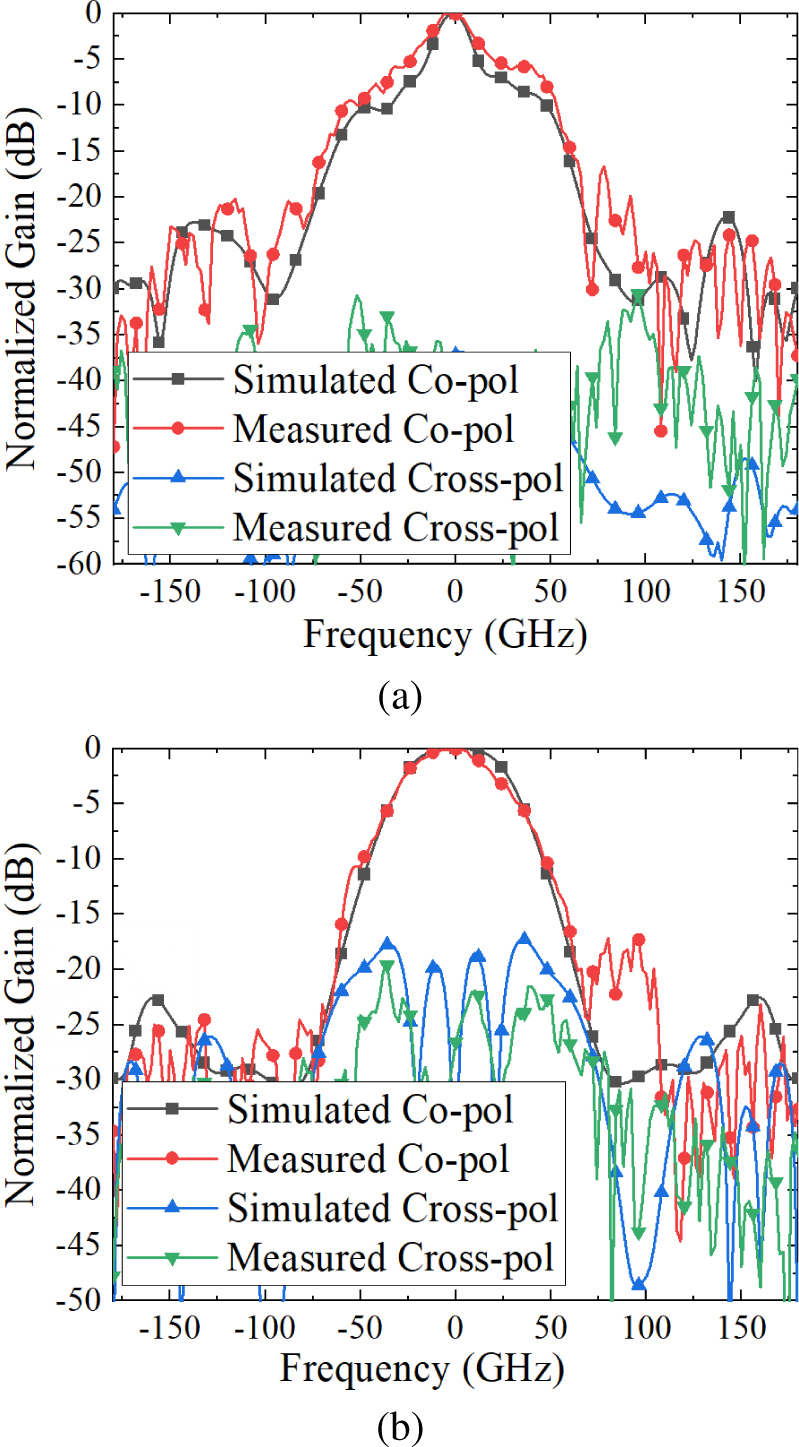
Figure 10: Simulated and measured radiation patterns of the proposed antenna at 7.5 GHz in (a) xoz and (b) yozplane.
Table 1: Comparison with other FPC antennas
| References | Bandwidth (%) | Gain (dBi) | Overall size () |
|---|---|---|---|
| [7] | 6.4 | 12.4 | 2.262.260.25 |
| [8] | 1.5 | 16.27 | 440.125 |
| [9] | 2.1 | 11.5 | 1.431.430.167 |
| [10] | 4.1 and 2.7 | 10.1 and 15.2 | 1.49 1.49 0.28 and 2.67 2.67 0.49 |
| [11] | 3.1 | 17 | unknownunknown0.25 |
| [12] | 4 | 4.1 | 1.11.10.075 |
| [14] | 2.8 | 13.4 | 2.62.60.36 |
| [15] | 32.4 | 13.67 | 4.494.490.57 |
| This work | 13.04 | 14.5 | 2.52.50.25 |
The performances of the proposed antenna compared with the references are illustrated in Table 1. The bandwidth is the intersection of impedance bandwidth and 3 dB gain bandwidth, and is the wavelength at center frequency. Compared with antennas in [8] and [11], the gain values of the proposed antenna is a little lower, while, the gain bandwidth in this paper is wider and the dimension is smaller. In addition, compared to all references except [15], the proposed antenna has a wider bandwidth. In [15], the height of the Fabry-Perot antenna is more than a half wavelength, which brings in wider bandwidth. Compared with [15], the proposed antenna in this paper has a smaller dimension and higher gain values.
V. CONCLUSIONS
The design and fabrication of a low profile broadband Fabry-Perot resonant cavity antenna is presented in this paper. The impedance bandwidth and gain bandwidth are wide by designing a partially reflective surface and loading a parasitic patch above the feed antenna. As a result, the final antenna provides an impedance bandwidth from 7 to 8 GHz (13.3%) and a 3 dB gain bandwidth from 7.02 to 8.10 GHz (14.3%). Afterwards, the addition of a metal reflector plate around the antenna further increases the maximum gain value to 14.5 dBi without affecting the bandwidth. Both the simulated and measured results verified this improvement. The presented antenna offers the advantages of large bandwidth, high gain and low profile, making it suitable for high-capacity microwave communications in the C-band, such as satellite communications and healthcare services.
ACKNOWLEDGMENT
This work was supported by the Natural Science Basic Research Program of Shaanxi (Program No. 2022JQ-699, 2022JQ-633 and 2021JQ-710) and the Key Research and Development Program of Shaanxi (Program No. 2021GY-049).
REFERENCES
[1] M. M. Bilgic, and K. Yegin, “High gain, wideband aperture coupled microstrip antenna design based on gain-bandwidth product analysis,” Applied Computational Electromagnetics Society (ACES) Journal, vol. 29, no. 8, pp. 639–646, Sep. 2021.
[2] J. Wang, Y. Li, Z. H. Jiang, T. Shi, M. C. Tang, Z. Zhou, Z. N. Chen, and C. W. Qiu, “Metantenna: When metasurface meets antenna again,” IEEE Transactions on Antennas and Propagation, vol. 68, no. 3, pp. 1332–1347, Mar. 2020.
[3] R. Gardelli, M. Albani, and F. Capolino, “Array thinning by using antennas in a Fabry-Perot cavity for gain enhancement,” IEEE Transactions on Antennas and Propagation, vol. 54, no. 7, pp. 1979–1990, July 2006.
[4] F. Deng and K. M. Luk, “A wideband spherical Fabry-Perot cavity antenna based on positive phase gradient metasurface,” IEEE Transactions on Antennas and Propagation, vol. 71, no. 7, pp. 5558–5565, July 2023.
[5] S. Fang, L. Zhang, Y. Guan, Z. Weng, and X. Wen, “A wideband Fabry-Perot cavity antenna with single-layer partially reflective surface,” IEEE Antennas and Wireless Propagation Letters, vol. 22, no. 2, pp. 412–416, Feb. 2023.
[6] R. Orr, G. Goussetis, and V. Fusco, “Design method for circularly polarized Fabry-Perot cavity antennas,” IEEE Transactions on Antennas and Propagation, vol. 62, no. 1, pp. 19–26, Jan.2014.
[7] Z.-G. Liu, Z.-X. Cao, and L.-N. Wu, “Compact low-profile circularly polarized Fabry-Perot resonator antenna fed by linearly polarized microstrip patch,” IEEE Antennas and Wireless Propagation Letters, vol. 15, pp. 524–527, 2016.
[8] M. Y. Jamal, M. Li, K. L. Yeung, X. Li, L. Jiang, and T. Itoh, “A low-profile Fabry-Pérot cavity antenna using anisotropic metasurface,” IEEE Antennas and Wireless Propagation Letters, vol. 21, no. 2, pp. 356–360, Feb. 2022.
[9] Z.-G. Liu, C. Zhang, R.-J. Yin, and W.-B. Lu, “Multifunctional low-profile Fabry-Perot resonator antenna integrated with solar cells,” IEEE Transactions on Antennas and Propagation, vol. 70, no. 8, pp. 7175–7180, Aug. 2022.
[10] J. Chen, Y. Zhao, Y. Ge, and L. Xing, “Dual-band high-gain Fabry-Perot cavity antenna with a shared-aperture FSS layer,” IET Microwaves, Antennas & Propagation, vol. 12, no. 13, pp. 2007–2011, July 2018.
[11] X. Zhao, Y. Liu, J. Zhang, and W. Zhang, “Design of a low-profile Fabry-Perot resonant cavity antenna using fractal EBG ground plane,” in 2021 International Conference on Microwave and Millimeter Wave Technology (ICMMT), pp. 1–3, Nanjing, China, 2021.
[12] G. V. Trentini, “Partially reflecting sheet arrays,” IRE Transactions on Antennas and Propagation, vol. AP-4, no. 4, pp. 666–671, Oct.1956.
[13] N. Wang, C. Zhang, Q. Zeng, N. Wang, and J. Xu, “New dielectric 1-D EBG structure for the design of wideband resonator antennas,” Progress in Electromagnetics Research Letters, vol. 141, pp. 233–248, 2013.
[14] Y. Wang and A. Zhang, “Dual circularly polarized Fabry-Perot resonator antenna employing a polarization conversion metasurface,” IEEE Access, vol. 9, pp. 44881–44887, 2021.
[15] S. Fang, L. Zhang, Y. Guan, Z. Weng, and X. Wen, “A wideband Fabry-Perot cavity antenna with single-layer partially reflective surface,” IEEE Antennas and Wireless Propagation Letters, vol. 22, no. 2, pp. 412–416, Feb. 2023.
BIOGRAPHIES

Xueyan Song was born in Henan Province, China, 1989. She received the B.E. degree in electronic and information engineering from Xidian University, Xi’an, China, in 2012. She received the Ph.D. degree from Xidian University, Xi’an, China, in 2018. She joined the School of Electronic Engineering, Xi’an University of Posts & Telecommunications in 2018. Her research interests include artificial magnetic conductors, low RCS antennas, low-profile antennas, frequency selective surfaces, and reflector antennas.

Ang Dong was born in Hebei, China, in 1999. He is currently pursuing a Master of Engineering degree in the School of Electronic Engineering, Xi’an University of Posts & Telecommunications. His current research interests include metasurface, microstrip antenna.

XuPing Li was born in Xi’an, Shanxi, China, in 1981. He received the Ph.D. degree in Electromagnetic field and microwave from the Xidian University, Xi’an, China, in 2015. In January 2019, he was transferred to Xi’an University of Posts & Telecommunications as the leader of the phased array antenna technology research team. The principal focus of his research program is the development of phased array antennas.

YunQi Zhang was born in BaoTou, Inner Mongolia, China, in 1986. He received the Ph.D. degree from Xidian University, Xi’an, China, in 2015. He is currently working in the Xi’an University of Posts & Telecommunications. His research interests include GPS antenna, CP antenna, omnidirectional antenna and antenna array designs.

Haoyuan Lin was born in Shandong, China, in 2003. He is currently pursuing B.E. degree in the school of Electronic Engineering from Xian University of Posts & Telecommunications. His current research interests include circuit, microwave, antenna.

Hailong Yang received the B.S. in communicating engineering from Heze University, Heze, China, in 2012, and M.S. and Ph.D. degrees in communicating engineering from Xi’an University of Technology, Xi’an, China, in 2015 and 2019. He joined the faculty of Electronic Engineering Department, Xi’an University of Posts & Telecommunications, in 2019. His research interests include wave propagation and antenna design.

Yapeng Li received the Doctor’s degree from Xidian University in 2020. He is currently an associate professor with the School of Electric Engineering, Xi’an University of Posts & Telecommunications. His research interests include filtering antenna, wideband antenna, dual-polarized antenna and circular polarized antenna.
ACES JOURNAL, Vol. 39, No. 3, 262–267
doi: 10.13052/2024.ACES.J.390312
© 2024 River Publishers