Design of 44 Multi-layer Butler-like Matrix with Flexible Phase Differences and Filtering Integration for 5G Applications
Li Ma, Lei Wang, and Xiaodong Chen
Department of Mobile Communications and Terminal Research
China Telecom Research Institute, Guangzhou, 510000, China
mal1@chinatelecom.cn, wanglei1@chinatelecom.cn, chenxiaodong@chinatelecom.cn
Submitted On: January 8, 2024; Accepted On: March 11, 2024
ABSTRACT
A universal topology for the filtering integrated Butler-like matrix (BLM) with flexible beam steering has been proposed based on the N/2 N Butler matrix (BM). This structure is constructed on three-layer circuits, with compact size and no crossover owing to the path distribution. Besides, the filtering function has been integrated into the BLM by utilizing the multi-stage coupled lines. For validation, a 44 BLM operating at 4.9 GHz was designed and fabricated. Measured results reveal that the 44 BLM exhibits a working bandwidth of 18.4% and filtering integrated functions, with a compact size of 1.22.3 . The measured scatting parameters and phase characteristics show great agreement with the simulated ones.
Index Terms: Antenna array, Butler matrix, filtering, multi-layer circuit, flexible phase differences.
I. INTRODUCTION
The development of wireless communication and growing demands for high-speed data services has raised higher requirements for the coverage and capability for the 5G signals and terminals [1]. Flexible BPNs are an ideal solution to extend the radiation range of antenna arrays (AA) in practical engineering. The implementation of smart antennas in the existing wireless communication depends a lot on the flexible BPNs. Among them, Butler matrix (BM) is the most widely used. For a conventional 44 BM with the distance between adjacent radiation elements being half a wavelength, the beam direction is fixed at 48.6 and 14.5 respectively [2–5]. However, in realistic employment, BMs with arbitrary phase differences (A-PD) are desired for flexible beam coverage of the smart antenna arrays. High-order BM is one of the approaches of exploring the beam’s controllability so as to broaden the radiation angle. In other ways, standard BM could be integrated with switching networks [6], or A-PD elements [7] to realize flexible phase differences.
BMs with various circuit structure and multiple function integration have been studied in various ways, such as multilayered printed circuit board (PCB) construction [8], CMOS technologies [9] and so on. In [10], a low-loss PET-based 44 BM has been designed with fixed phase differences of 45 and 135. Additionally, BM now has a filtering option, which simplifies the system, improves the performance, and reduces the complexity. Nevertheless, research on integrated filter antennas that are excited by nearby input ports and have variable beam spacing and arbitrary beam direction is still required.
In this paper, a multilayer configuration of the BM has been presented with theorical analysis, design procedure, and experimental verification. The generalized coupling network (GCN) consisting of power dividers, phase shifting units, and shunt single-pole-double-throw (SPDT) switches, has been introduced to construct the Butler-like matrix (BLM). This paper is an expansion of the authors’ previous work in [11]. Advantages of this BM lies in three aspects: 1) an original circuit configuration with compact size and no crossover, 2) flexible phase differences for the beam steering and beam controllability, and 3) wideband and filtering functions integrated for practical applications. Compared with the author’s former work [11] and the related A-PD antenna arrays in [10] and [2–13], our improvements and contributions are as follows. The universal topology of the BLM with flexible phase differences has been designed and explained, with the design theory under two different working states illustrated in detail. The relationship between the beam-steering properties of the proposed topology with the phase differences of the BLM and the parameters of components are delivered and analyzed, which are also compared with the conventional ones to highlight the advantages of this BLM structure. Furthermore, the design procedure of the beam has been explored from 44 to NN beamforming networks. Moreover, for validation, the 44 BLM has been designed, fabricated, and measured. Both simulated and measured results coincide well with each other. Measured results reveal that the 44 BLM exhibits a wide working bandwidth and compact size with filtering integrated functions and flexible phaseproperties.
II. DESIGN THEORY OF BLM
The topology and configuration of the BLM is illustrated in this section, following by the design theory of the phase differences and the relation with beam steering for the BLM and BFN. A 44 BLM has been taken as an example, then the design procedure has been expanded to NN BLM.
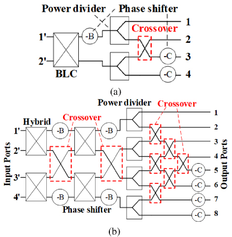
Figure 1: Conventional (a) 24 and (b) 48 BMs.
A. configuration of the 44 BLM
In view of the symmetry of the BM structure, the proposed NN BLM can be divided into two N/2N BM structures. Traditional N/2N BM has complex structures and large number of components, as shown in Fig. 1. Considering that those two BMs have many overlapping parts, the 44 BLM can be constructed in two ways: a single 24 BM structure with two reconfigurable working states, or two independent 24 BM structures grouped through SPDT switches.
As shown in Fig. 2 (a), a couple of 24 BM structures can generate different beam distributions by the alternation of working State 1 and State 2. For example, SPDT switches are used to access different phase shifters related to different states. In Fig. 2 (b), two states of independent 24 BM structures are adopted, defined as State 3. The schematics of the 44 BLM shown in Fig. 2 possess four input ports 1’, 2’, 3 ’, 4’ and four output ports 1, 2, 3, 4. The output ports are connected and switched through a group of parallel SPDT switches. The 24 BM structure is constructed on a three-layer circuit, so that the crossover could be eliminated by multilayer configuration. Then we can get a 44 BLM structure similar to a conventional 44 BM, which is easy to analyze and is illustrated later.
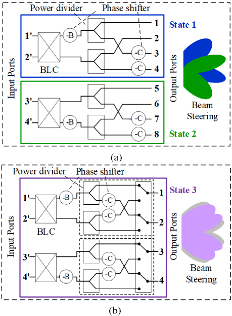
Figure 2: Schematics of the proposed 44 BLM based on 24 BM, working at (a) State 1 and 2, (b) State 3.
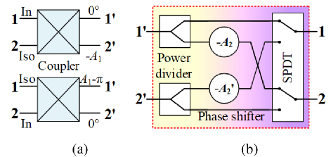
Figure 3: Schematics of (a) A-PD coupler, (b) GCN.
A four-port generalized coupled network (GCN) is designed to construct the BLM, which is composed of two power dividers, two phase-shift units, and two shunt SPDT switches, as shown in Fig. 3. The forward phase difference A excited by port 1 and the reverse phase difference A’ excited by port 2 are no longer limited to A+A’=180. The first-stage coupling structures connected with the outputs are two GCNs, with forward phase differences of A, A and reverse phase differences of A’, A’. The coupling structures in the second stage close to the input consist of two traditional couplers with forward and reverse phase differences of A, A and A’, A’. Two phase shifters with phase shifts of B, B are arranged. When fed by port i’, the phase of output ports m and n are and , with the phase differences being =- (i, m, n1,2,3,4).
Table 1: Phase responses of the 44 BLM
| Port1 | Port2 | Port3 | Port4 | |
| Port1’ | -B1 | -A3 | -B1-A1 | -A2-A3 |
| Port2’ | -B1-A3’ | 0 | -B1-A1-A3’ | -A2 |
| Port3’ | -A1’ | -B2-A2’-A4 | 0 | -B2-A4 |
| Port4’ | -A’-A’ | -B-A’ | -A’ | -B |
B. Phase differences of the 44 BLM
When the input ports 1’4’ are excited respectively, the phase responses of the BLM are shown in Table 1. The phase differences between port m and m+1 for different input ports can be summarized as follows:
| (1) |
where A A- A, A’ A’ - A’. According to different sets of the GCN’s phase differences, the performances of the BLMs are discussed respectively.
There is A+ A’ = 180 for an arbitrary coupler in a universal BLM with equal phase interval (EPI), which brings about the restriction between and . Besides, there is B+B= 90. The phase differences of the neighboring output ports can be re-written as
| (2a) | ||||
| (2b) | ||||
| (2c) | ||||
| (2d) |
It is apparent that all the output phase differences are bound up with a single variable of A. By introducing the arbitrary-phase-difference (A-PD) couplers, the phase differences would vary with A, referring to an A-PD BLM with flexible beam controllability.
The phase differences of BLM with equal phase differences satisfies –= –= - , simplified as (i1,2,3,4). The design parameters of the BLM EPD can be calculated by
The sum of forward and reverse phase differences for couplers A (or A) is 180, which is consistent with the design schemes above. The inherent properties contribute to the limitation of the phase differences: - = 180, - = 180.
Traditional BMs are composed of 90 hybrids and 45 phase shifters, defined as Case A with A= A= A= A= 90, B= B= 45. It means that the output phase differences have fixed values of -45, 135, -135, and 45. By introducing the arbitrary-phase-difference (A-PD) couplers, the phase differences would vary with A, referring to an A-PD BLM with flexible beam controllability. For example, given that Case B with A= A= 130, A’ = A’ = 50, A= A= 90, and B= 25, B= 65, the BLM EPI possesses the flexible phase differences of = -65, = 115, = -155, and = 25. The array patterns of this A-PD 44 BM in Case B is depicted in Fig. 4 (a) with comparison to Case A. The ideal simulated results are calculated by MATLAB. It can be seen that the phase intervals of any two-output ports with adjacent beams are 90.
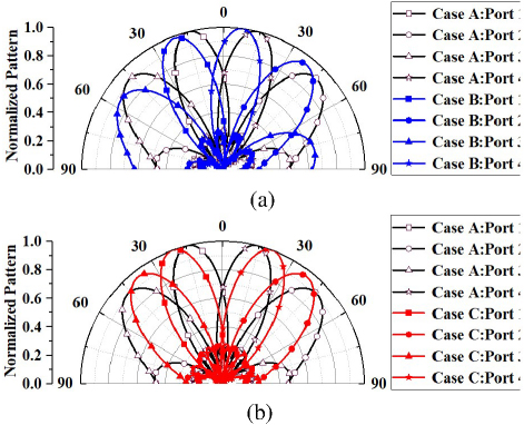
Figure 4: Array patterns of traditional BM in Case A with (a) BLM EPI in Case B and (b) BLM UEPI in Case C.
Although the universal BLM EPD based on traditional couplers can extend the range of the radiation beam angles, it suffers from two main defects: a) phase intervals between adjacent output ports are fixed inherently; b) the beams of the antenna fed by BLM EPI are not symmetrical about the vertical axis of = 0.
In order to solve the defects of BLM EPI, the restrictions of the forward and reverse phase differences for couplers A (or A) should be broken. According to formula (3), it can be obtained that the situation of A+ A’ 180 needs to be considered, which means A (or A) and A’ (or A’) could be designed flexibly and arbitrarily. The relationships between and in (2d) are re-defined as
| (4) |
The phase intervals between two output ports with adjacent beams can be calculated by [11]:
| (5) |
From (5) we can see that the phase intervals are no longer constant at 90. That is, the phase differences of the BLM with unequal phase interval (UEPI) relevant to A (or A) and relevant to A’ (or A’) could be designed independently and respectively. For simplification, assume that A and A is 90. Then combining (2), (4), and (5), the design equations could be derived as
| (6) |
Take a BLM UEPI as Case C, with A= A’ = A= A’ = 130, A= A= 90, and B= B= 25 for example; this would produce phase differences of -65, 115, -115, and 65 under the excitation of P1’P4’. A symmetrical distribution relationship appears for the array patterns of this BLM UEPI, as illustrated in Fig. 4 (b).
C. Design procedures of the NN BLM
In general, we extend the design schemes to the NN BLM with N = 2 input or output ports. There are n-stage coupling structures, each stage of which includes N/2 coupling networks. The phase differences of the output ports are recorded as . On the basis of with the constructions and analysis cases, the properties of the proposed BLM based on four-port GCNs have been summarized in the following:
a) All the coupling structures on the first stage have the same positive and negative output phase differences to achieve equal phase differences.
b) The relationship between and is determined by the sum of the positive and negative output phase differences coupling structure on the first stage. The relationships of and are relevant to the sum of the positive and negative output phase differences coupling structure on stage 2n.
c) The coupling structures on the first stage have been designed as four-port GCNs, and those on the second to the n stages are 90-degree hybrids. The phase differences of the BLMs would be carried out according to the analysis and iterations.
III. SIMULATION AND EXPERIMENT
A. Circuit constitution
The parameters of the proposed 44 BLM are set up according to equations (2) to (6), distributed on Ro4730 with the relative permittivity 3.0 and loss tangent 0.002. The overall circuits are distributed on three layers, as shown in Fig. 5, the middle of which acts as the reference ground, and the thickness between each layer is represented as h = 30 mil. The BLM consists of two multi-layer couplers, two phase shifters, and two filtering GCNs, skipping the crossover. All the units of the BLM will be introduced respectively.
The couplers in the first stage are branch line couplers (BLC) with two sections. The circuits on the top layer and those on the bottom layer are symmetrical about the ground. Each layer of the BLC has two transmission lines, possessing impedance Z and electrical length = /4, and three stubs, with impedance and electrical length of (Z, ) on either side and (Z, ) in the middle. The end of the three stubs on Layer 1 is connected with those on Layer 3 by metal vias passing through the ground. Owing to the symmetric structure of the proposed coupler, the scatting parameters can be analyzed and calculated by the even- and odd- modetheory.
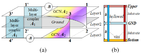
Figure 5: (a) Schematic and (b) cross section of the BLM.
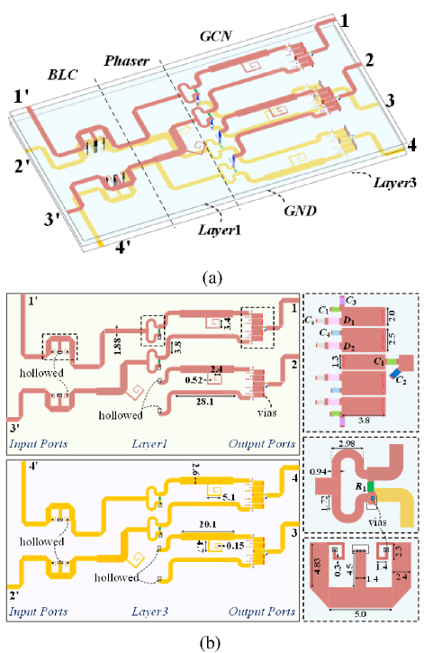
Figure 6: Schematics of the 44 BLM: (a) 3D layout and (b) top view with physical parameters.
The couplers in the second stage are GCNs, which are composed of power dividers, phase-shifting structures, and filtering switches. The circuit parameters of the multistage coupled-line structure and lumped elements in the filtering SPDT switch can be obtained based on the analysis of the equivalent circuit model by transforming transmission line sections into J-inverters. The capacitors CCare shorted with metal vias into the ground plane on Layer 2 for the DC terminal. Then the GCN shows a forward phase difference of A and reverse phase difference of A’ when different signal paths of the SPDT are switched on. The phase control units provide phase shifts of A and A’ for the forward and reverse phase differences of GCN, respectively.
The three-layer topology of the proposed 44 BLM has inherent isolation for different paths so that the numbers of crossovers are decreased.
B. Simulated and measured results
A 44 BLM working at 4.9 GHz with unequal phase intervals and equal phase differences has been designed and simulated by employing design parameters of A= A= 60, A= A= 90, and B= B= 60. The 3D layout and top view of the multi-layer circuit have been shown in Fig. 6, of which each unit is designed as mentioned before. Considering the BLM is arranged symmetrically to the horizontal central line, performances of the BLM when P1’ (or P2’) is excited are the same as those under the excitation of P4’ (or P3’). A coupler working at 4.9 GHz and relative bandwidth of 40% is designed and optimized by employing the full-wave EM simulator.
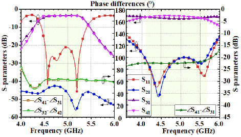
Figure 7: Simulated S-parameters and phase differences of the coupling networks in (a) first stage and (b) second stage.
The simulated S-parameters and the phase properties of both the first coupling network as BLC and the second coupling structure of GCN are displayed in Fig. 7 [11]. The physical parameters of the BLC are shown in Fig. 6 when Z= 42.6 , Z= 113 , and Z= 62.6 . Besides, the metal ground of Layer 2 is hollowed out around the vias to avoid earth short. The proposed GCN is composed of two power dividers, two phase shifting structures, and two filtering SPDT switches with C and C being 0.3 pF, C being 0.2 pF, and C being 1 pF. The diodes DD employ SMP1345-079LF (with L= 0.7 nH, R= 2 , and C= 0.15 pF). The capacitors and resistors are implemented in 0402 and 0603 size respectively. Besides, both the forward and reverse phase differences are around 60, breaking the limitation A + A’ = 180 of normal BLC.
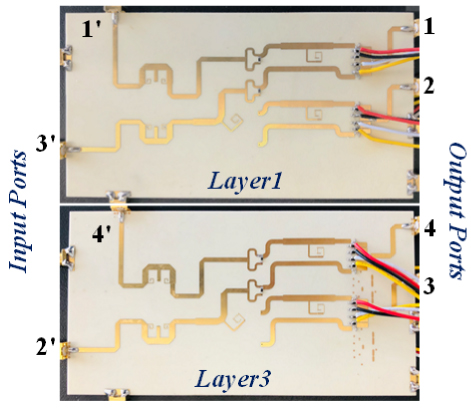
Figure 8: Photograph of the fabricated BLMs.
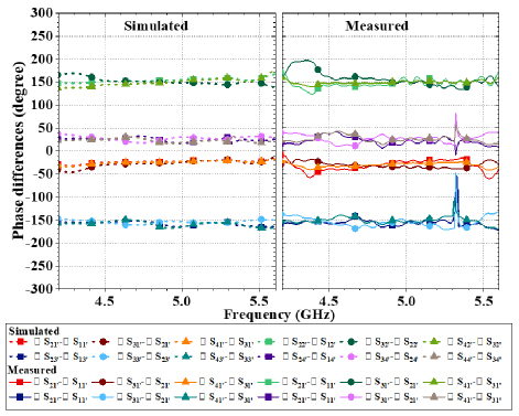
Figure 9: Simulated and measured phase differences between adjacent output ports of the 44 BLM with P1’-P4’ excited.
The fabricated BLM, as illustrated in Fig. 8 working at 4.9 GHz employs the design parameters of A= A= A’ = A’ = 60, A= A= A’ = A’ = 90, and B= B= 60. In Fig. 9, the simulated and measured phase shifters of the BLM have been illustrated. In the simulated phase shifters of the 44 BLM with P1’P4’ excited respectively, there is flexible phase differences of = -30, = 150, = -150, and = 30. While forming the measured results of the BLM, the phase differences at 4.9 GHz are about -32.7 -27.6, 145.5 151.4, -161.2.4 -151.8, and 17.9 25.0 with P1’P4’ excited, respectively.
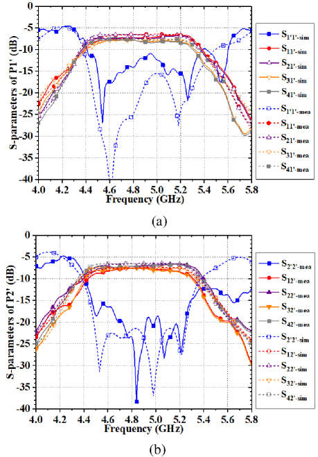
Figure 10: Simulated and measured S-parameters of the 44 BLM with (a) P1’ and (b) P2’ excited.
Figure 10 shows the simulated and measured S-parameters of the BLM. As we know, the input ports P1’ and P4’ of the proposed BLM are symmetric; so are P2’ and P3’. Thus, only the experimental results under the excitation of P1’ and P2’ are presented in this case. According to the simulated scatting parameters, the bandwidth of the 44 BLM (with S, S, S, and S below 15 dB) is about 0.9 GHz (18.4%) ranging from 4.4 GHz to 5.3 GHz. As for the experimental results measured by the Vector Network Analyzer, the return losses and isolations are better than 11 dB for the working band from 4.4 to 5.3 GHz. When P1’ is excited, the measured transmission coefficients from P1’ to P1P4 are -9.6-7.5, -8.6-7.8, -10.0-9.5, and -9.9-9.1 dB. When P2’ is excited, the measured transmission coefficients of S’, S’, S’, and S’ are -9.6-7.5, -8.6-7.8, -10.0-9.5, and -9.9-9.1 dB.
C. Beam steering of AA with proposed BLM
The radiation pattern has been calculated with the simulated and measured results in the previous sections. Figure 11 reveals that the normalized measured radiation beams point to -8.5 for the input port P1’, 42.7 for input port P2’, -45.3 under the excitation of P3’, and 7.9 when P4’ excited. The beams show symmetry distribution with respect to the vertical axis, consistent with the desired effect.
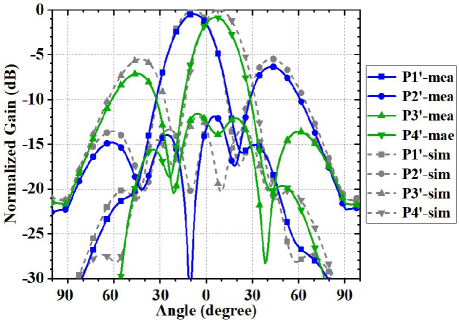
Figure 11: Radiation patterns of linear antenna array fed by the proposed 44 BLM with measured results.
IV. CONCLUSION
In this paper, a universal topology of the filtering-integrated BLM with arbitrary phase phases has been proposed in three-layer construction. The 44 BLM operating at 4.9 GHz were designed, fabricated, and measured, exhibiting a bandwidth about 18.4% and a compact size of 1.22.3 . The proposed BLM possesses such characteristics as compact size, filtering integration, wide working band, and flexible phase differences. It is worthy for further application to smart antennas and wireless communications.
ACKNOWLEDGMENT
This work was supported in part by National Key Research and Development Program of China (No. 2021YFB2900303). This paper is an expanded version from the International Applied Computational Electromagnetics Society (ACES) Symposium, Hangzhou, China, Aug. 2022 [11].
REFERENCES
[1] E. Dahlman, G. Mildh, S. Parkvall, J. Peisa, J. Sachs, Y. Selén, and J. Sköld, “5G wireless access: Requirements and realization,” IEEE Commun. Mag., vol. 52, no. 12, pp. 42-47, Dec. 2014.
[2] N. Tiwari and T. R. Rao, “A switched beam antenna array with Butler matrix network using substrate integrated waveguide technology for 60 GHz radio,” Applied Computational Electromagnetics (ACES) Journal, vol. 31, no. 5, pp. 599-602, Aug. 2021.
[3] K. Tekkouk, J. Hirokawa, R. Sauleau, M. Ettorre, M. Sano, and M. Ando, “Dual-layer ridged waveguide slot array fed by a butler matrix with sidelobe control in the 60-GHz band,” IEEE Trans. Antennas Propag., vol. 63, no. 9, pp. 3857-3867, Sep. 2015.
[4] W. Yang, Y. Yang, W. Che, C. Fan, and Q. Xue, “94-GHz compact 2-D multibeam LTCC antenna based on multifolded SIW beam-forming network,” IEEE Trans. Antennas Propag., vol. 65, no. 8, pp. 4328-4333, Aug. 2017.
[5] H. N. Chu and T.-G. Ma, “An extended 44 Butler matrix with enhanced beam controllability and widened spatial coverage,” IEEE Trans. Microw. Theory Techn., vol. 66, no. 3, pp. 1301-1311, Mar. 2018.
[6] F. E. Fakoukakis and G. A. Kyriacou, “On the design of a Butler matrix-based beamformer introducing low sidelobe level and enhanced beam-pointing accuracy” in Proc. IEEE-APS Top. Conf. Antennas Propag. Wireless Commun. (APWC), pp. 12-16, Sep. 2011.
[7] Y. Wu, J.-Y. Shen, Y. Liu, S.-W. Leung, and Q. Xue, “Miniaturized arbitrary phase-difference couplers for arbitrary coupling coefficients,” IEEE Trans. Microw. Theory Techn., vol. 61, no. 6, pp. 2317-2324, June 2013.
[8] A. A. M. Ali, N. J. G. Fonseca, F. Coccetti, and H. Aubert, “Design and implementation of two-layer compact wideband Butler matrices in SIW technology for Ku-band applications,” IEEE Trans. Antennas Propag., vol. 59, no. 2, pp. 503-512, Feb. 2011.
[9] B. Cetinoneri, Y. A. Atesal, and G. M. Rebeiz, “An 88 Butler matrix in 0.13-m CMOS for 5-6-GHz multibeam applications,” IEEE Trans. Microw. Theory Techn., vol. 59, no. 2, pp. 295-301, Feb. 2011.
[10] S. A. Babale, “PET-based instant inkjet-printed 44 Butler matrix beamforming network,” Applied Computaional Electromagnetics (ACES) Journal, vol. 37, no. 02, pp. 199-208, July 2022.
[11] L. Ma, “Design of multi-layer filtering Butler-like matrix with flexible phase differences,” Applied Computational Electromagnetics (ACES) Journal Symp., July 2022.
[12] Y. M. Hussein, M. K. A. Rahim, N. A. Murad, and H. O. Hanoosh, “Low loss wideband 44 Butler matrix networks based on substrate integrated waveguide for 5G applications,” IEEE Access, 2023. doi:10.1109/ACCESS.2023.3342713
[13] S. Tang, Y. Zhang, J. Rao, Z. Han, C.-Y. Chiu, and R. Murch, “Beamforming network design utilizing node microstrip architectures for dual-polarized endfire millimeter-wave antenna arrays,” IEEE Trans. Antennas Propag., vol. 71, no. 6, pp. 4862-4873, June 2023.
BIOGRAPHIES

Li Ma received the B.S. degree and the Ph.D. degree in electronic science and technology from Beijing University of Posts and Telecommunications (BUPT), Beijing, China, in 2017 and 2022, respectively. She is currently working as a researcher at the Department of Mobile Communications and Terminal Research of China Telecom Research Institute. Her research interests include wireless communication, microwave components, and antenna technology.

Lei Wang is a senior engineer of China Telecom. He received the B.S. and M.S. degrees in information and communication engineering from the Xidian University, Xi’an, China, in 2001 and 2004, respectively. He is now working as a senior engineer at the Department of Mobile Communications and Terminal Research of China Telecom Research Institute. His research interests include 5G communications and key technology of terminals.

Xiaodong Chenis a deputy senior engineer of China Telecom. He received the B.S. and M.S. degrees in communication and information system from the South China University of Technology, Guangzhou, China, in 1999 and 2002, respectively. From 2002 to 2011, he was a researcher with the Wireless Communication Department of Guangdong Scientific Telecommunication Academy. From 2012 to 2023, he was a project manager and a senior expert of the Mobile Communication Department of China Telecom Research Institute. His research interests include backscatter communications and 6G vision.
ACES JOURNAL, Vol. 40, No. 2, 130–137
doi: 10.13052/2025.ACES.J.400206
© 2025 River Publishers