Cable Interference Analysis of Gas Insulated Substation Based on Domain Decomposition Method-Multilevel Fast Multipole Algorithm
Abdul Mueed, Weiqiang Tang, Muhammad Asif, and Rui Ma
1College of Electrical and Information Engineering
Lanzhou University of Technology, Lanzhou, GanSu 730022 China
engr.mueed@live.com, twqzjh@163.com, 18294916381@163.com
2Education Department
Khyber Pakhtunkhwa 25000, Pakistan
asifpk003@gmail.com
Submitted On: January 9, 2024; Accepted On: August 18, 2024
ABSTRACT
To explore cable interference in gas insulated substations (GIS), this paper proposes a reliable and efficient computational approach. The hybrid domain decomposition method-multilevel fast multipole algorithm (DDM-MLFMA) is presented herein. This technique determines the specifications of GIS cables for RG58 and AWG23. Self and mutual interference are identified utilizing very fast transient overvoltage (VFTO) transient interference signal.This hybrid technique offers a numerical simulation to replicate the impact of the VFTO interference signal. Utilizing the matrix-vector multiplication (MVX) product to address compression and approximation challenges, the hybrid approach proves reliable and pragmatic. Because of its computational nature and explicit factorization reduction, this strategy reduces computation time and memory requirements. Consequently, the system’s complexity follows a linear trend under this proposed approach. The computed results are juxtaposed with traditional methodologies to validate the effectiveness of the proposed algorithm.
Index Terms: Computational memory, computational time, domain decomposition, hybrid algorithm, interference measurement, multilevel fast multipole method, very fast transient overvoltage interference signal.
I. INTRODUCTION
The substation is the hub of power transmission and transformation. The utilization of gas insulated substation (GIS) switching techniques has led to the generation of rapid transient events termed very fast transient overvoltages (VFTO). During the propagation of VFTO in GIS, catadioptric reflection takes place, subsequently coupling to the GIS shell and emitting outward into the external space.
The EM transient phenomena occurs in the GIS substation by the leakage of isolation gasses due to voltage level increases. This signal/behavior effects the secondary side due to its enormous amplitude and complicated composition of frequency (VFTO signal). This penetration occurs via power cable connection [1–4].
The automation of the secondary side in GIS substations has received significant attention over the past decade. Secondary equipment produces current or voltage through the transformation process and powerful transient EM fields are produced in space. Additionally, coupling is used to safeguard the cable through EM radiation. The surge VFTO signal effects secondary side equipment and becomes a key factor in the design of EMC in a GIS substation [5–8].
Due to continual advancements in digital and intelligent substation technology, GIS installations incorporate a greater number of secondary intelligent electronic devices equipped with control, protection, and communication capabilities. It is crucial to note that substation operations may generate electromagnetic interference that poses a risk to the safe and reliable functioning of the substation. This interference has the potential to cause malfunctions and damage to electronic equipment. The VFTO procedure and related risks are depicted in Figs. 1 and 2.
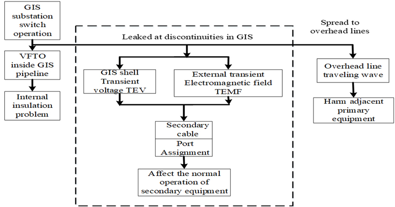
Figure 1: The very fast transient process and its hazards.
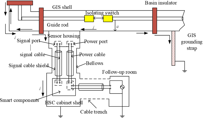
Figure 2: The principle of interference voltage generated by GIS switch operation on equipment ports.
The next hazard is frequency components composed in this waveform. There are several types of high frequency components present in the power frequency components. The frequency range is 1 MHz-1 GHz and the current method is fast Fourier transform (FFT). In Fig. 3, the VFTO waveform also contains the frequency components 40 MHz, 56 MHz, and 88 MHz corresponding to the 5th, 7th, and 11th harmonic frequency components of 8 MHz, respectively.
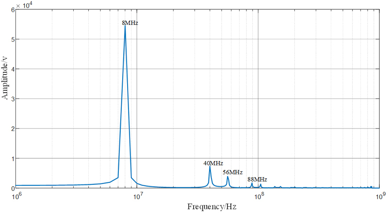
Figure 3: The VFTO frequency components.
Numerous theories regarding EM interference in GIS substations have been explored. The concept of coupling transmission line field lines has been addressed [9–10], alongside Agrawal’s theory on multiconductor transmission lines [11]. Additionally, discussions on lossy and lossless lines are included [12].
A time domain model has been developed to estimate secondary cable interference in GIS substations [13]. Yamamura et al. [14] presented a numerical calculation approach for determining the common-mode induced voltage of shielded cables in substations, utilizing the transmission line theory of the mirroring principle. Acatauassu et al. [15] have showcased the occurrence of transient overvoltage in shielded cables.
As per the study by Yan et al. [16], finite difference techniques have been investigated for scattering and radiation problems involving narrow wires. Recent advancements in high-frequency theories and research have led to a greater utilization of multi-conductor stranded cables. Calculating the electrical crosstalk/interference parameters for such cables at high frequencies is not particularly challenging [17–18].
In the GIS substation with multistrand cables, various numerical techniques such as the moment method [19–20], FDTD techniques [21–22], advanced modeling techniques [23], domain decomposition method [24], and traditional FEM approach [25] are employed to conduct interference analysis.
Due to the non-linear nature of the memory parameters, additional iterations are necessary for convergence, prompting the utilization of FEM for computation. This results in an increase in complexity. When employing standard FEM for analysis, the complexity in terms of memory size also escalates.
Domain decomposition is based on tetrahedra (triangles) to form a mesh. However, this method demands a considerable number of operations to solve the resulting equations.
The fast multipole method (FMM) [26–27] speeds up the matrix-vector multiply in the conjugate gradient (CG) method when it is used to solve the matrix equation iteratively. FMM with the formula of combined field integral equation (CFIE) has been derived, where the complexity of the matrix-vector multiplication reduces from O(N) to O(N), where N is the number of unknowns. The ray-propagation fast multipole algorithm [28–29] with nonnested method, further reduces to O(N). Hence, we implement the multilevel fast multipole algorithm (MLFMA), whose complexity reduced to O(NlogN). As a result, we employ the hybrid domain decomposition method-multilevel fast multipole algorithm (DDM-MLFMA) technique to overcome the computational deficiencies inherent in conventional methods. This article focuses on analyzing interference/crosstalk in cables utilized within GIS substations. The DDM-MLFMA algorithm is employed to calculate both self and mutual interference. Additionally, computational parameters including computational time, memory usage, errors, and efficiency are evaluated.
This article is structured as follows. In section I, we attempt a GIS literature review. In section II, the mathematical equations of cable modelling parameters are described. Section III covers the comprehensive procedure about the hybrid algorithm (DDM-MLFMA). In section IV, proposed cable model simulation and validation of results are presented. Finally, section V concludes our work.
II. CABLE MODEL BUILDING
The model is composed of a single-core wire and a shielded wire as mentioned in the two sets of transmission line loops. The signal applies on the shielded wire core and induces current on the shielding layer. Hence, an induced voltage is generated at its port. The equivalent circuit model parameters are shown in Fig. 4. Z, Z, Z, and Z are 50 , and both ends of the shielding layer are directly grounded.
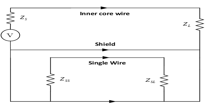
Figure 4: Equivalent circuit model of shielded wire and single core wire.
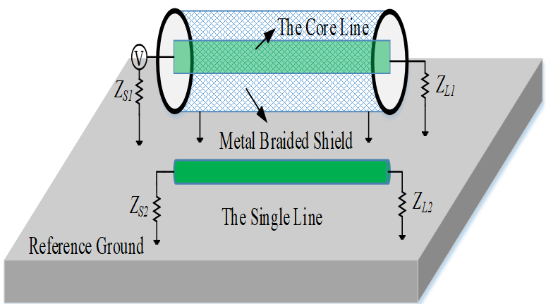
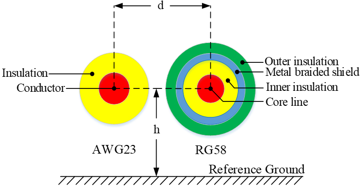
Figure 5: Schematic diagram of crosstalk model: (a) radial diagram and (b) sectional view.
According to transmission line theory, the current distribution on the inner core of the wire is:
| (1) |
where I and Z represent the excitation current and internal impedance of the inner core wire, and Z and represent the characteristic impedance and propagation constant of the inner transmission line loop, respectively. The shielding layer does not contain an excitation source. The voltage source generated by the current on the inner core wire at any position z of the shielding layer is:
| (2) |
In this section, the theoretical calculation and simulation verification of the crosstalk of the specific model are carried out. The model of the shielded wire is RG58 and the model of the single-core wire is AWG23. The radial and cross-sectional schematic diagrams are shown in Fig. 5. The specific parameters of the model are shown in Table 1.
Specific parameters of the model are shown in Table 1.
Table 1: RG58 and AWG23 cable parameters
| Parameter | Size |
| Relative distance between cables d | 3 mm |
| Height over the ground h | 10 mm |
| Single core conductor radius | 0.2865 mm |
| Insulation thickness of single core wire | 0.19 mm (PE) |
| Line length | 1 m |
| Inner core wire radius | 0.47 mm |
| Inner insulation layer thickness | 1.005 mm (PE) |
| Shield thickness | 0.325 mm |
| Outer insulation thickness | 0.5 mm (PVC) |
| Termination resistance | 50 |
III. HYBRID ALGORITHM
By combining one or more asymptotic and numerical techniques, the hybrid approach improves the accuracy of solving electromagnetic problems. Originally designed to improve algorithmic performance, the hybrid approach focused on fusing asymptotic and numerical techniques to address challenging structural problems. These methods can be used on large or small surfaces, depending on how complicated the issue is. This approach has the benefit of offering useful solutions for large and complex technical challenges. In our case, transient electromagnetic interference is estimated using huge and irregular structures. The hybrid algorithm is DDM-MLFMA.
This hybrid algorithm uses a hybrid approach. First, convert the irregular shapes that are decomposed into a regular surface (# of triangles). Then, use the matrix-vector multiplication (MVX) principle to compute the interference and computing parameters. The computation is done through the far and near interaction field, which is based on the domain specified by the domain decomposition method (DDM).
A. Domain decomposition method
The non-overlapping DDM has become a potent and attractive tool for numerically rigorous solutions of Maxwell’s equations, which is based on the divide-and-conquer strategy. The original problem is divided into smaller, potentially repeating and simpler, subdomains rather of being addressed as a whole. To enforce the continuation of electromagnetic fields, some suitable boundary requirements known as transmission conditions are required at the interfaces between adjacent subdomains. Iteratively, these transmission requirements are imposed. Subdomains interact with one another, starting with arbitrary initial assumptions for each, until a specific convergence in the solution is achieved [30].
The straightforward geometrical multi-section method is used for domain decomposition. The domain can be divided into as many subdomains as desired, each of which has an equal number of cells per processor. To create the desired number of subdomains, the domain is divided along its largest dimension using the domain decomposition technique. This pruning can (and typically is) done recursively to newly created subdomains. Since each subdomain is stored in a distinct file and the cells are sorted using the quick-sort method, the process is extremely speedy.
Moreover, embedded DDM have many advantages, which can be to discretize one domain into subdomains. Thus, we can make an embedded mesh of complicated geometries by dividing them into many small subdomains, from which we get a good quality of mesh. Therefore, small subdomain meshes and matrix assembly are independent. Recomputing the DDM subdomain and adding another subdomain will support EM modeling and practical design solutions.
For electrically large EM problems, direct inversion methods such as Gaussian elimination or LU decomposition can no longer be applicable due to O(N) memory and O(N) central processing unit (CPU) time requirements, where N is the number of unknowns. Iterative solution methods such as the conjugate gradient (CG) method are the only options but their convergences are often chaotic or failing. Much of the work in the DDM in this aspect is related to the selection of the transmission conditions to ensure the convergence of the DDM algorithm. When transmission conditions are properly devised, DDM becomes an effective preconditioner for such problems. Furthermore, memory requirements can be greatly reduced since DDM can be easily parallelized with MLFMA.
B. Multilevel fast multipole algorithm
MLFMA is an iterative approach that accelerates MVX, resulting in lower memory requirements and faster computation. A multilevel solver, MLFMA is based on the working principle of MVX product. MLFMA is used to compute the number of operations and the memory usage by the extraction of sparse matrix. Additionally, it is an almost matrix-free solver and only needs (NlogN) memory. Furthermore, it has been demonstrated that the MLFMA can be applied to dense matrices with FEM up to 10 million unknowns. As a consequence, MLFMA minimizes complexity and memory requirements. In order to achieve (NlogN) complexity, the MLFMA employs aggregation, translation, and disaggregation.
The MLFMA algorithm is based on expansion and approximation of the first kind Hankel function. The integral equation can be solved iteratively, which involves the MVX product: MVX performed by the MLFMA solver and having (M+1)(N+1) matrix-vector equation. This algorithm reduces the memory requirement from to . In MLFMA, the far-field is effectively calculated in a group-to-group for basis function and testing function. The MLFMA is a well-organized solver that can optimize computations. Additionally, the Lagrange interpolation method significantly improves the efficiency and accuracy of proposed solver. This Lagrange method is used to fill the translation matrix entries of large-scale EM problems, but the number of interpolation and sampling points are fixed. This speeds up the simulation i.e. reduces the computation time.
To develop the fast and hybrid multilevel algorithm (DDM-MLFMA), the whole geometry is composed of one big cube (known as a group). The big cube is divided into eight small cubes (subgroups/subblocks). Each subcube is divided into smaller cubes. This smaller cube is divided into the finest level with each cube having the length of half a wavelength. Every cube has to be categorized. By comparing the basis function of the center cube with other centered cubes, we may determine the cube at the highest level in which each basis function can be found, while checking for nonempty cubes.
C. Implementation of DDM with MLFMA
To implement the hybrid DDM-MLFMA multilevel algorithm, the entire object is first decomposed into a larger cube, which is partitioned into eight smaller cubes. Each subcube is then recursively subdivided into smaller cubes until the edge length of the finest cube is about half of a wavelength. An index number is assigned to all levels of cubes. At the finest level, each basis function is assigned to a cube by comparing its center coordinates with the cube’s center. We further find nonempty cubes by sorting. Only nonempty cubes are recorded using tree structured data at all levels. Thus, the computational cost depends only on the nonempty cubes.
The basic algorithm for matrix vector multiply is broken down into two sweeps. The first sweep consists of constructing outer multipole expansions for each nonempty cube at all levels. The second sweep consists of constructing local multipole expansions contributed from the well-separated cubes at all levels. When the cube becomes larger as one progresses from the finest level to the coarsest level, the number of multipole expansions should increase. In the first sweep, the outer multipole expansions are computed at the finest level, and then the expansions for larger cubes are obtained using shifting and interpolation.
Let and be the cube centers at level and , respectively, then the outer multipole expansions for coarser level should be:
| (3) |
has only values, and we need values of . Therefore, we will interpolate to values first. That is:
| (4) |
where interpolation matrix W is a sparse matrix.
At the coarsest level, the local multipole expansions contributed from well-separated cubes are calculated using the basic multipole equation. At the second sweep, the local expansions for smaller cubes include the contributions from the parent cube using shifting and interpolation and from the well-separated cubes at this level but not well-separated at the parent level. If the local multipole expansions received by a cube center at level l-1 is, then the contribution from all well-separated cubes can be written as:
| (5) |
where is the weighting function. If we put the interpolation expression for into equation (C.) and change the order of two summations this leads to:
| (6) |
The above operation is called interpolation. At the finest level, the contributions from non-well-separated cubes are calculated directly. Since only nonempty cubes are considered, the complexity for MLFMA is reduced to O(NlogN) and the memory requirements for MLFMA are of the order O(NlogN).
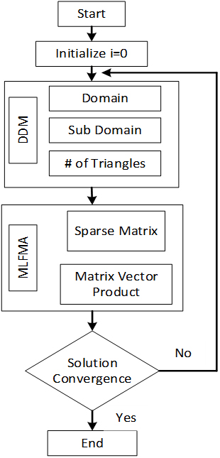
Figure 6: Flowchart of hybrid DDM-MLFMA.
This method is instigated in three phases. First step is aggregation, second step is translation, and final step is disaggregation. At the first level of the group, the field of each group is acquired and connected with its center of geometry. Hence, this point is chosen as first aggression point. In the solution steps, this first level of group is amassed into a larger group. The principles of aggression of the lower group(s) contained in each high-level groups (cubes) are evaluated through shifting and interpolation to reduce computing resources. When the first step is completed, a translation occurs between separated groups, but the group belongs to the same level. Finally, when all the cubes have received a contribution from all other cubes of the same level, these influences are released to the inherited cubes through shifting and translation as mentioned in the aggression step. The flowchart of the hybrid algorithm is shown in Fig. 6.
IV. RESULTS AND DISCUSSION
A. The numerical model
This section focuses on the power cable, exploring transient analysis for various cable pairs. Specifically, RG58 and AWG23 configured as a twisted pair is utilized for VFTO analysis.
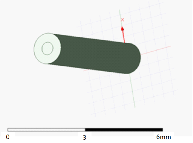
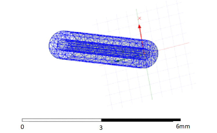
Figure 7: Cable geometry: (a) the model and (b) meshed view.
Based on the geometrical dimensions and materials, the electromagnetic interference simulation model is built, as shown in Fig. 7. The characteristics and configurations of the bus bars and conductors, as well as their computational models, are important considerations when examining the electromagnetic interference and crosstalk properties of the GIS substation. Different tube/conductor thicknesses (5 mm, 10 mm) are taken into account throughout the estimating procedure, and their effect on electromagnetic shielding performance is investigated. There are two different kinds of cables in this model. Figure 6 has comprehensive explanations of the model, meshing, and surface field representation.
More meshes result in a greater confinement of convergence of the solution. In the hybrid technique suggested, mesh refinement reduces geometry factors that aid in solution prediction. Increasing the number of meshes also lowers system complexity. As a result, the suggested approach is dependable and improves the DDM-MLFMA algorithm’s accuracy.
The algorithm needs the number of passes, number of iterations, and convergence value to estimate the solution. The hybrid algorithm must follow the criteria of admissibility for the conversion process. It means that the far-field and near-filed matrices are well-mannered to compute the assemblies of the matrix. The beauty of this algorithm requires a smaller number of operations for the estimation of interference parameters. The convergence is shown in the Fig. 8.
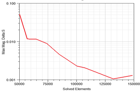
Figure 8: Solution convergence criteria.
B. Interference measurement
In such cases, there are two different types of crosstalk. When the effects are the same, there is self-pair/self-strand interference. Self-interference is shown in Fig. 9.
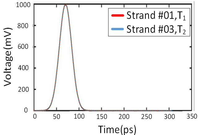
Figure 9: Self-pair effect of VFTO signal.
Crosstalk refers to the mutual interference between pairs or strands, occurring when they interact. This type of interference manifests as transient effects on other pairs, as depicted in Fig. 10.
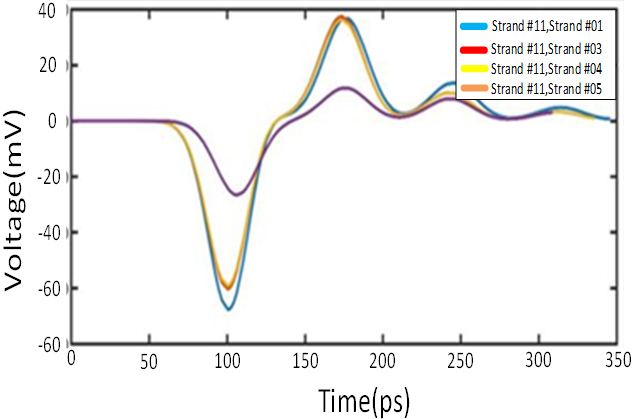
Figure 10: Mutual pair effect of VFTO signal.
Figures 11 and 12 depict the electric and magnetic field distributions along the selected calculation line for a frequency of 100 MHz within the conductor and a casing thickness of 5 mm.
According to Figs. 12 and 13, the electric field magnitudes caused by the electromagnetic interference source are 35316.780 and 27822.773, respectively, while the corresponding magnetic field strengths are 154.277 and 113.440.
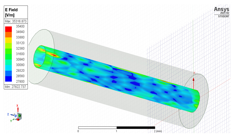
Figure 11: Electric field of GIS EM interference.
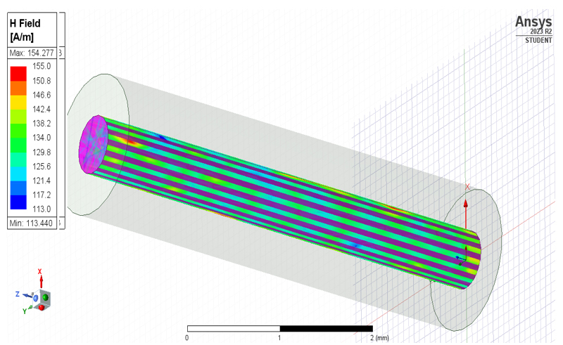
Figure 12: Magnetic field of GIS EM interference.
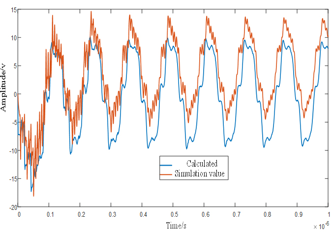
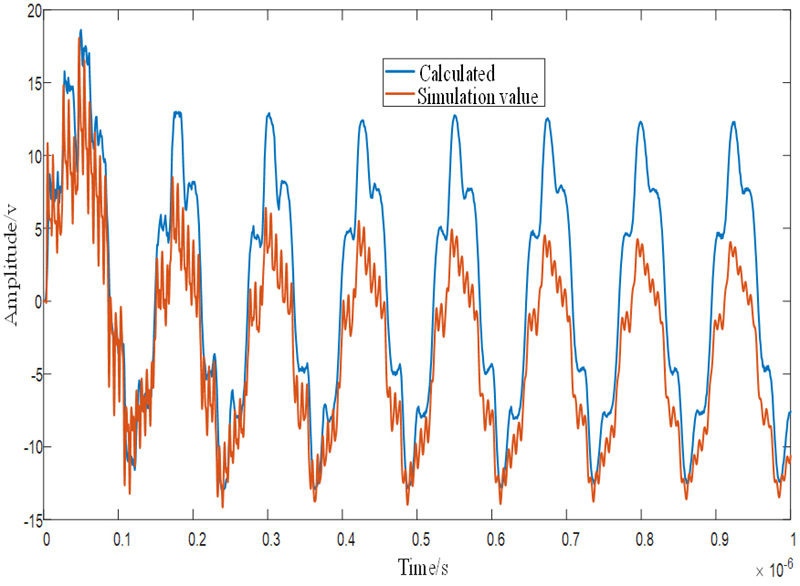
Figure 13: Response voltage waveforms at two ports of a single-core wire: (a) near-end voltage waveform and (b) far-end voltage waveform.
As the electromagnetic field moves approaching the shielding (second pair), the electromagnetic field variation curve shows noticeable attenuation. During switching operations, the GIS metal conductor exhibits efficient shielding against radiated electromagnetic fields produced by the electromagnetic interferencesource.
The GIS conductor’s magnetic field shielding effectiveness reaches 240.5 dB at the same frequency of 100 MHz, while its electric field shielding effectiveness registers at -90 dB and -10 dB at a shell thickness of 2 mm. This emphasizes how effectively high-frequency electromagnetic radiations are shielded by the GIS conductor tube.
The experimental procedures are adopted to calculate the interference in the proposed cables model in the GIS substation. The proposed power cable model is simulated and designed in the HFSS portfolio. The excitation signal is used as the VFTO signal to obtain the crosstalk effect of the signal on the inner core. At the same time, the numerical simulation value is calculated through a hybrid algorithm. The comparison is made as shown in Figs. 13 (a) and (b).
There is an acceptable level of agreement between the hybrid algorithm and the HFSS simulation, even though the former oscillates less than the latter. This difference could be the result of radiation losses during computation, which the HFSS simulation did not take into consideration.
The voltage waveform is represented in Fig. 13. The red line is the simulated data and the blue line is a representation of the calculated data through the equations (proposed algorithm). Both results are compatible with each other. It means that the proposed algorithm is validated. The estimated value (experimental measurement) of the suggested approach is essentially consistent with the waveform size and trend of the simulated value, as can be seen in Fig. 13. This confirms the suggested method’s efficacy. However, a few errors in the peak value are unavoidable and are shown for the following two aspects: (1) there will be some discrepancy between the theoretically estimated and actual measurements of the transmission impedance, and (2) there are specific errors in the interference parameter matrix that are determined by the ANSYS program.
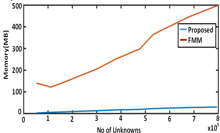
Figure 14: Memory comparison of proposed method.
C. Computational parameters
In this section, the computing parameters are estimated through the hybrid algorithm. This hybrid algorithm reduces the number of operations to solve the matrix assembly. The graph is drawn between the numbers of unknowns (matrix assembly) and the computational memory. In Fig. 14, the x-axis represents the number of unknowns (matrix assembly needed to be solved) and y-axis represents the computational memory. Fig. 14 estimates how many matrix assemblies have to be solved: the blue line displays the result of the proposed method, and the red line represents the traditional MLFMA result.
The matrix-vector product is employed by the MLFMA to calculate memory usage. As a result, the usual approach involves additional processes, which increases system complexity. The resulting slope is nonlinear. The suggested approach applies the Garlinken’s function, which is independent. This function needs fewer steps to achieve solution convergence. As a result, the system’s complexity becomes linear, as seen in Fig. 14. The computational memory is shown in Table 2.
Table 2: Computational memory parameters
| No of Unknowns | Memory (MBs) | No of Adaptive Passes |
| 349722 | 30.103 | 1 |
| 428992 | 32.337 | 2 |
| 428992 | 31.200 | 3 |
| 545330 | 42.343 | 4 |
V. CONCLUSION
In this paper, the electromagnetic interference model of GIS is established. Based on electromagnetic computational theory, the effectiveness analysis of GIS cabling is analyzed. EMI interference and computing parameters are evaluated through the hybrid algorithm. The beauty of the hybrid algorithm is that it speeds up the estimation process due to the explicit nature of Garlinken’s function. This reduces the computing time and memory size and, ultimately, the size of the system and cost is reduced because a smaller number of operations is required with comparison to the traditional FMA method. Hence, the system complexity becomes linear. As a result, the computed results validate the algorithm’s cogency. The computing results are superior to traditional computingmethods.
ACKNOWLEDGEMENT
This work was supported by the National Natural Science Foundation of China (Grant numbers 62063018, 62463017).
REFERENCES
[1] E. Kuffel, W. S. Zaengl, and J. Kuffel, High Voltage Engineering: Fundamentals. Amsterdam: Elsevier, 2000.
[2] B. Liu, G. Ye, and Y. Tong, “Influence of disconnector in gas insulated switchgear switching on/off on electromagnetic compatibility of electronic transformer,” High Voltage Engineering, vol. 44, no. 4, pp. 1204-1210, 2018.
[3] S. Bai, L. Zeng, M. Rong, Y. Li, K. Chen, and Y. Zhang, “Interference analysis and protection of electronic current transformer caused by disconnect switch operation in GIS,” High Volt. Appar., vol. 52, pp. 54-62, 2016.
[4] M. Rao, M. Mohana, M. Joy Thomas, and B. P. Singh, “Insulated substation model during switching,” Journal of Electrical Engineering and Technology, vol. 2, no. 3, pp. 306-311, 2007.
[5] M. Rao, M. Mohana, M. Joy Thomas, and B. P. Singh, “Transients induced on control cables and secondary circuit of instrument transformers in a GIS during switching operations,” IEEE Transactions on Power Delivery, vol. 22, no. 3, pp. 1505-1513, 2007.
[6] T. Yang, L. Huang, J. Wu, J. Huang, K. Xu, Y. Zhu, and X. Wu, “Study on the electromagnetic shielding characteristics of GIS shell,” International Journal of Electrical Energy, vol. 7, no. 1, pp. 31-35, 2019.
[7] J. Liu, F. P. Dawalibi, and B. F. Majerowicz, “Gas insulated substation grounding system design using the electromagnetic field method,” in 2012 China International Conference on Electricity Distribution, pp. 1-6, 2012.
[8] J. I. Jianfei, W. Lihui, Y. Yubo, and Y. Yifei, “Experimental analysis of EMC immunity for field installed intelligent equipment, of intelligent substation,” in 2014 China International Conference on Electricity Distribution (CICED), pp. 1556-1564, 2014.
[9] Z. Ma, J. Jasni, M. Z. A. Ab Kadir, N. Azis, J. Xie, and Y. Ma, “Simulation of lightning strikes to 1000 kV UHV-AC double-circuit transmission lines,” in 2023 IEEE International Conference on Power Science and Technology (ICPST), Kunming, China, pp. 980-985, 2023.
[10] H. Xue, A. Ametani, and J. Mahseredjian, “Very fast transients in a 500 kV gas-insulated substation,” IEEE Transactions on Power Delivery, vol. 34, no. 2, pp. 627-637, 2018.
[11] A. K. Agrawal, H. J. Price, and S. H. Gurbaxani, “Transient response of multiconductor transmission lines excited by a nonuniform electromagnetic field,” IEEE Transactions on Electromagnetic Compatibility, vol. 2, pp. 119-129,1980.
[12] C. R. Paul, Analysis of Multiconductor Transmission Lines. Hoboken, NJ: John Wiley and Sons, 2007.
[13] D. Hui and Z. Liang, “Simulation of electromagnetic interference coupling to a substation secondary cable,” in 2010 Asia-Pacific International Symposium on Electromagnetic Compatibility, 2010.
[14] M. Yamamura, Y. Kami, K. Murano, and F. Xiao, “Analysis of transmission characteristics for twisted pair cables using the RLGC parameters of the cable,” in 2015 Asia-Pacific Symposium on Electromagnetic Compatibility (APEMC), Taipei, Taiwan, pp. 720-723, 2015.
[15] D. Acatauassu, S. Höst, Chenguang Lu, M. Berg, A. Klautau, and P. O. Börjesson, “Simple and causal twisted-pair channel models for G.fast systems,” in 2013 IEEE Global Communications Conference (GLOBECOM), Atlanta, GA, pp. 2834-2839, 2013.
[16] Y. Yan, L. Meng, X. Liu, T. Jiang, J. Chen, and G. Zhang, “An FDTD method for the transient terminal response of twisted-wire pairs illuminated by an external electromagnetic field,” IEEE Transactions on Electromagnetic Compatibility, vol. 60, no. 2, pp. 435-443, Apr. 2018.
[17] Y. X. Sun, Q. Li, W. H. Yu, H. Jiang, and Q. K. Zhuo, “Study on crosstalk between space transient interference microstrip lines using finite difference time domain method,” The Applied Computational Electromagnetics Society Journal (ACES), vol. 30, no. 8, pp. 891-897, 2015.
[18] D. A. Weston, Electromagnetic Compatibility: Methods, Analysis, Circuits, and Measurement. Boca Raton: CRC Press, 2016.
[19] W. Xin, G. Zhang, W. Yuan, J. Wu, and Y. Geng, “Calculation of transient electromagnetic fields generated during switching operation in power substation by the method of moment and superposition principle,” in 2013 2nd International Conference on Electric Power Equipment - Switching Technology (ICEPE-ST), Matsue, Japan, pp. 1-4,2013.
[20] T. Lu, X. Cui, M. Ianoz, and D. Tabara, “Prediction of switching transient electromagnetic fields in gas-insulated substations,” in 2002 3rd International Symposium on Electromagnetic Compatibility, Beijing, China, pp. 182-185,2002.
[21] Y. Yan, L. Meng, X. Liu, T. Jiang, J. Chen, and G. Zhang, “An FDTD method for the transient terminal response of twisted-wire pairs illuminated by an external electromagnetic field,” IEEE Transactions on Electromagnetic Compatibility, vol. 60, no. 2, pp. 435-443, Apr. 2018.
[22] Q. Q. Liu, Y. Zhao, C. Huang, W. Yan, and J. M. Zhou, “A new method for stranded cable crosstalk estimation based on BAS-BP neural network algorithm combined with FDTD method,” The Applied Computational Electromagnetics Society Journal (ACES), pp. 135-144, 2020.
[23] X. Pei, W.-W. Ran, and P.-A. Du, “An analytic method of determining a critical cable spacing for acceptable crosstalk,” The Applied Computational Electromagnetics Society Journal (ACES), pp. 237-244, 2020.
[24] S. Khan, Y. Zhao, Y. Wei, A. Mueed, Z. Ullah, and A. Khan, “Simulation of high frequency twisted pair cable using DDM-FEM hybrid algorithm,” The Applied Computational Electromagnetics Society Journal (ACES), pp. 109-116, 2022.
[25] W. Yu, Z. Huang, S. Pan, J. Yan, K. Fu, B. Li, and Y. He, “Finite element analysis-based impedance calculation of GIS station horizontal pipeline considering magnetization curve,” in International Conference on Wireless Power Transfer, Singapore, pp. 493-501, 2023.
[26] J. Barnes and P. Hut, “A hierarchical O (N log N) force-calculation algorithm,” Nature, vol. 324, pp. 446-449, 1986.
[27] C. R. Anderson, “An implementation of the fast multipole method without multipoles,” SIAM Journal on Scientific and Statistical Computing, vol. 13, no. 4, pp. 923-947, 1992.
[28] R. Coifman, V. Rokhlin, and S. Wandzura, “The fast multipole method for the wave equation: a pedestrian prescription,” IEEE Antennas and Propagation Magazine, vol. 35, no. 3, pp. 7-12, June 1993.
[29] S. Velamparambil and W. C. Chew, “Analysis and performance of a distributed memory multilevel fast multipole algorithm,” IEEE Transactions on Antennas and Propagation, vol. 53, no. 8, pp. 2719-2727, Aug. 2005.
[30] L. Yin and W. Hong, “A fast algorithm based on the domain decomposition method for scattering analysis of electrically large objects,” Radio Science, vol. 37, no. 1, pp. 1-9, Jan. 2002.
BIOGRAPHIES

Weiqiang Tang was born in Wuzhou, China. He received the B.S. degree in Automation from Lanzhou University of Technology, Lanzhou, China, in 2003; the M.S. degree in Control Theory and Control Engineering from Lanzhou University of Technology, Lanzhou, China, in 2008; and the D.S. degree in Control Science and Engineering from Xi’an Jiaotong University, Xi’an, China, in 2012. His research interests include advanced control theory and its application and robust control.

Abdul Mueed was born in Bhakkar, Pakistan. He received the master’s degree in electrical engineering from the University of Engineering and Technology, Taxila, Pakistan, in 2015. From 2009 to 2017, he worked as a Lecturer in Electrical Engineering at the Dr. A. Q. Khan Institute of Technology, Mianwali, Pakistan. He is currently working as a Research Scholar at Lanzhou University of Technology, Lanzhou, China. His primary research interests include electromagnetic compatibility problems, computational electromagnetics, power system transients, EMC related application in biomedical engineering, and application of artificial intelligent in EMC.

Rui Ma was born in Gansu, China. He received the master’s degree in control theory and engineering from Lanzhou University of Technology, Lanzhou, China, in 2024. He is currently studying for his Ph.D. at Lanzhou University of Technology, majoring in pattern recognition and intelligent systems. His main research focus are intelligent control and motion control.

Muhammad Asif was born in Khyber Pakhtunkhwa, Pakistan. He received his bachelor’s degree from University of Science and Technology, Bannu, Pakistan. He has worked as BSS Engineer in ZTE. Currently working in the Education Department Khyber Pakhtunkhwa, Pakistan. His main research is related to electromagnetic computability, controller designing and power converters, and control systems.
ACES JOURNAL, Vol. 39, No. 9, 831–840
doi: 10.13052/2024.ACES.J.390909
© 2024 River Publishers