FEM Simulation of Severe Stator Winding Inter-turn Short Circuit Faults of Outer Rotor DFIG
H. Mellah, A. Maafa, H. Sahraoui, A. Yahiou, S. Mouassa, and K. E. Hemsas
1Electrical Engineering Department
Faculty of Applied Sciences, University of Bouira, Bouira 10000, Algeria
h.mellah@univ-bouira.dz, omaafa@univ-bouira.dz, abdelghani.yahiou@univ-bouira.dz souhil.mouassa@univ-bouira.dz
2Electrical Engineering Department
LAS Laboratory, Sétif 1 University, Sétif, Algeria
hemsas_ke_dz@univ-setif.dz
3Electrical Engineering Department
University of Chlef, Chlef, Algeria
h.sahraoui@univ-chlef.dz
Submitted On: January 11, 2024; Accepted On: June 26, 2025
ABSTRACT
Recently, in wind power generation, doubly-fed induction generators (DFIG) have been commonly employed, and their capacity is also increasing, making DFIG’s security and reliability more significant. Stator winding inter-turn short-circuit faults (SWITSCF) are a prevalent flaw of theirs. In this paper, a DFIG has been modeled by the finite element method (FEM) in the healthy state and in the faulty state. Several simulations have been carried out for different number of inter turn short-circuit faults (NSWITSCF) to see their effects on the DFIG performance. SWITSCF modifies the impedance, which affects the current amplitudes and phases. As a consequence, the current is asymmetric where a negative sequence component is observed. SWITSCF gives the cause of the existence of the short-circuit current that generates an additional magnetic field. This will make the magnetic circuit largely saturated. Furthermore, with the NSWITSCF increasing, these negative effects appear stronger and move away from a healthy state.
Index Terms: Doubly fed induction generator (DFIG), finite element method (FEM), number of inter turn short-circuit faults (NSWITSCF), outer rotor, wind turbine.
I. INTRODUCTION
Early in the development of human civilization, wind power was exploited, initially for the propulsion of sailing vessels and subsequently for the powering of windmills [1]. Nevertheless, a foundation for wind energy research was not created and explicitly applied to power generation until the early twentieth century, due to the work of numerous scientists in the field of aerodynamics [1, 2]. Modern wind energy conversion technology has developed since the 1970s, with rapid progress observed in the 1990s. References [1–3] show that worldwide markets are interested in renewable energy and have expanded their investments, their worldwide revenue exceeding US$285 billion, which was more than double their investment in conventional energy sources by the end of 2015. According to [3], China is the leader both for wind installations and for capacity added in 2017, followed by the USA and Germany. Different wind turbine concepts have been developed and improved, as well as various wind generators [2, 4]. Many researchers are interested in how to detect and localize the stator winding inter-turn short-circuit faults (SWITSCF) for the stator and for the rotor [5–10].
We can summarize the methods to model SWITSCF in doubly-fed induction generators (DFIG) by two approaches: analytic and numeric [5–11]. Authors [12–16] examined some of the consequences of the stator’s ITSCF on DFIG performance with an internal rotor.
Wind energy is produced using DFIG, which can have either an inner [4] or an external [2] rotor. Their capacity is increasing, and the safety, reliability, and continuity of their work have become indispensable in light of the frequent energy crises. Through power electronics, grid-connection and variable wind speed operation are possible. DFIG grid connectivity problems have been addressed by numerous researchers [5–9]. These converters provide a bidirectional power flow between the machine and the network to support both modes of operation, either operating at sub-synchronous speeds or at super-synchronous speeds [22]. The algorithm used in the power electronics converter controls the frequency, phase, and terminal voltage of the DFIG [23]. Among the most well-known DFIG faults are the inter-turn short-circuit faults (ITSCF), whether they are in the stator or rotor windings.
Over the past 10 years, research on how SWITSCF affects DFIG performances has drawn a lot of attention [24]. In addition, many scholars have studied ways to identify and locate these kinds of failure [7, 25–28]. However, before electrical faults can be detected and localized, it is necessary to first have an understanding of the differences in behavior that exist between normal and fault conditions in electrical machines.
According to the literature [13–32], there are two approaches for examining the SWITSCF through numerical simulation in all electrical machines which are analytical or numerical approaches. The analytic method is founded on multi-circuit theory [33–35]. The numerical method is usually based on finite element method (FEM) [31, 36]. In order to analyze failure detection mechanisms, having a solid understanding of the DFIG fault through simulation models and features is absolutely necessary. Several studies have looked into a FEM-based model under ITSCF conditions for the stator or rotor winding [7, 12, 14, 16, 17, 26, 37, 38].
Han et al. [39] combines the unified spiral vector model with FEM for the purpose of performance evaluation of brushless doubly-fed induction machines with different rotor winding short circuits. An analytical and numerical model is proposed in order to study the scaling effect on SWITSCF in a permanent magnet generator [40]. Afshari et al. [42] looked at SWITSCF with different numbers of inter turn short-circuit faults (NSWITSCF). However, they only looked at the current behavior of the stator, and they only took slots 4 and 19 into account.
Chen et al. [26] present work with SWITSCF verified by experimentation as well as FEM modelling. Nevertheless, this study solely looks at how SWITSCF affects current and only for specific turns. Some researchers are limited to studying how a SWITSCF affects the magnetic flux density of the DFIG [37]. Three cases of ITSCF for phase A of the rotor winding, namely 2, 5, and 12, were studied by Li and Wang in [12]. Their effects were shown on the rotor current through their time-domain and frequency-domain representations for each case, as well as on the air gap magnetic flux density and the magnetic flux density distribution over the entire machine in each case. Afshari et al. [42], studied through the stator and rotor’s current spectrum formulation two closely related phenomena. They discuss SWITSCF and high-resistance connections, as well as the influence such connections have on the amount of energy that is pumped into the electrical grid during sub- and super-synchronous modes. Additionally, they covered how to differentiate between the two.
He et al. [16] provide a quantitative study of vibration, current, and loss characterization of air gap flux density distortion in the healthy case and in the short circuit case of a one-third turn of DFIG based on FEM. Chen et al. investigate how ITSCF affects stator branch currents in Phase A, expressing their findings in terms of total harmonic distortions (THD) and Park’s vector trajectory under various numbers of shorted turns from 1 turn to 9 turns [38]. Fu et al. [43] compute the bilateral flux linkage between stator winding and rotor winding based on the DFIG analytical model and use it as a means of SWITSCF detection. Rehman et al. are interested in the influence of SWITSCF rotor winding at different cases on the rotor current but limited their study on 2 slots [7]. The effect of a rotor ITSCF on the radial magnetic flux density of a large hydro generator based on FEM is investigated in [44], then is offered to detect these defects.
In this study, we modelled and simulated the healthy and unhealthy behavior of DFIGs in SWITSCF situations using FEM. We are interested in seeing the effect of SWITSCF on a DFIG with an outer rotor when we simulate the same DFIG but with different numbers of SWITSCF appointed by NSWITSCF for stator phase “A”. As a result, a comparison of the current time-domain representation for the three phases of a healthy and unhealthy stator has been presented, Frequency-domain representation for each case has also been investigated, and the distributions of magnetic flux density are presented for a constant speed operation.
The main objective of this research is to deal with the effect of major SITSCF on the DFIG current and magnetic distribution using the FEM and application of the FEM for the outer rotor DFIG under faults.
This paper introduces a time-domain representation of the three-phase stator currents under several NITSCFs to address the effect of this later on their wave forms. We also address the fast Fourier transform (FFT) of the stator current under different NITSCFs to clearly see their effects on the magnitude and harmonics and exploit them for future diagnostic work.
This paper is structured as follows. Section II presents a brief description of the DFIG wind turbine system. Section III presents some rating values and design specifications for the DFIG necessary to build the FEM model. Section IV deals with the simulation setup and steps and the obtained outcomes. Finally, section V concludes the paper by summarizing the findings and discussing future research directions.
II. DFIG WIND TURBINE SYSTEM
Danish scientist Poul la Cour (1846-1908) was the first to connect a windmill to a generator [45]. Three types of wind turbine are deployed in the market:
Fixed-speed wind turbine (FSWT) founded on the use of squirrel-cage induction generator (SCIG), which is connected to the grid directly via a transformer.
Variable-speed wind turbine (VSWT) based on DFIG associated with pitch control. The stator is directly connected to the grid, but the rotor is connected to the grid via a power electronics converter.
Variable-speed wind turbine based on a permanent magnet synchronous generator (PMSG), connected to the grid via an appropriate frequency converter [45].
The energy produced by a VSWT can typically be 2-6% greater than a FSWT, with one study claiming this may be as high as 39% [46]. Petersson [46] indicates that the actual value will depend on site conditions such as the speed and direction of the wind and would include all aspects of the design of the wind turbine. Moreover, a DFIG can increase significantly the energy produced by the wind turbine, with reported increases of 20% for a DFIG compared to a SCIG-based VSWT, and 60% compared to a FSWT [46].
As can be seen in Fig. 1, DFIG is frequently utilized as a primary component in wind turbine systems. In this configuration, the electrical grid is connected to both the stator winding and the rotor winding. The wind turbine converts the wind power (Pw) towards mechanical energy and the role of the DFIG is to convert this mechanical energy to electrical energy [4].
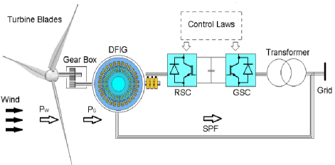
Figure 1: Typical configuration of a DFIG wind turbine.
The relationship between the frequency of the stator voltage and the frequency of the excitation currents in the rotor is exploited to keep the generation frequency constant and matched to the grid frequency. The algorithms for this are implemented in the power electronics converter [2]. The speed of the rotating magnetic field (n0) and the rotor shaft velocity (n) are coupled by the following equation:
| (1) |
In the case when n is less than n0, the stator and rotor currents are in phase and the rotor absorbs energy from the converter. In contrast, when n is greater than n0, the stator and rotor currents are not in phase and the rotor supplies electrical energy to the converter [2, 4].The input mechanical power Pneeded to reach the maximum power point (MPPT) of the wind turbine depends on the wind turbine power for the MPPT (Pm_ref) at the reference speed (ref) and the mechanical rotor speed m. Equation (2) should be met for MPPT [2]:
| (2) |
The mechanical loss of the rotor Pf is found in equation (3):
| (3) |
where Pf_refis mechanical loss measured at ref, giving the electromagnetic power for the DFIG as:
| (4) |
The DFIG output electrical power in the stator at rated operation is given by equation (5):
| (5) |
where m1 is the number of stator phases (in this case 3), R1 is the stator winding resistance of one phase and is assumed equal in all DFIG phases, V1, I1 and are the nominal values of the voltage, the current and the power factor of a stator phase. is:
| (6) |
III. DFIG GEOMETRY AND FEM MODEL
Table 1: Rating values and design specifications for the DFIG
| Design Specifications | Rating Value |
| Rated output power | 550 (W) |
| Rated voltage | 220 (V) |
| Rated speed | 157 (rad/s) |
| Poles | 4 |
| Stator slots | 24 |
| Rotor slots | 30 |
In finite element modeling, the first step involves constructing and sketching the geometric contours of the DFIG model depending on the specifications of a particular device that has been chosen. Tables 1–3 contain descriptions of some of their parameters. The next stage is to distribute specific materials and their qualities among the different zones. As an illustration, copper will be utilized for the conductors. Air will be used for the spaces between the conductors. In the following stage, phenomena and parameters will be incorporated. Voltage sources and mechanical loads, shaft speed, different boundary conditions, eddy currents, and the nonlinear behavior of the magnetic circuit are a few examples of these. Others include magnetic circuit saturation.
In order to attain the best possible outcomes, a finite element mesh is generated for each DFIG member, with an exceptionally tiny mesh being utilized for the air gap. The last step is to set the simulation parameters, which include the relative and absolute error levels, the simulation step, and the stop time.
Table 2: Dimensions of the stators and rotors periphery
| Parameter | Value (mm) |
| Stator external diameter | 120 |
| Inside stator diameter | 50 |
| Rotor external diameter | 180 |
| Inside rotor diameter | 121 |
| Length of stator and rotor core | 65 |
Table 3: Dimensions of the slots on both the stator and the rotor
| Dimension of the Stator Slot | Value (mm) | Dimension of the Stator Slot | Value (mm) |
| hs0 | 2 | h | 2 |
| hs1 | 2 | Hr1 | 2 |
| hs2 | 15 | hr2 | 10 |
| bs0 | 2.5 | br0 | 2.5 |
| bs1 | 9.19419 | br1 | 8.5281 |
| bs2 | 5.24462 | br2 | 10.6303 |
| rs | 2 | rr | 2 |
IV. SIMULATION OUTCOMES
This section presents the results of the simulations carried out in DFIG for a healthy case and various defective cases in Phase A of the stator winding which are 4, 11, 22, 33, and 39 NSWITSCF. Figure 2 provides a perspective in three dimensions of the DFIG that was designed. Although periodic boundary conditions are commonly used in FEM simulations for their computational efficiency, the occurrence of an ITSCF in Phase A introduces asymmetry into the model. Consequently, periodicity conditions cannot be applied, and a full model must be used to accurately represent the faulted behavior.
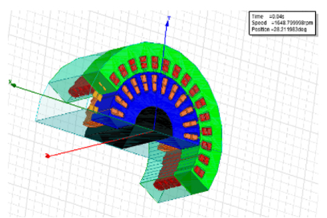
Figure 2: Three-dimensional view of a section of the designed DFIG.
The basic idea behind FEM is to divide the study domain into small pieces. In the ANSYS environment, the partial differential equation (PDE) is defined for each part of the DFIG. A 3D view of the DFIG outer rotor is depicted in Fig. 2. Figure 3 illustrates the mesh applied to the model. In this section, we also simulate DFIG with a different case of a NSWITSCF to show how the NSWITSCF affects the performance of DFIG.
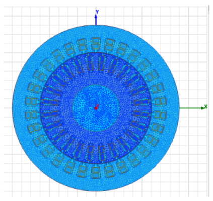
Figure 3: 2D DFIG outer rotor mesh.
A. Stator currents of Phase A
The stator current in Phase A for a typical case and various NSWITSCF conditions is shown in Fig. 4. Figure 4 compares the stator current waveforms under healthy conditions and different ITSCF scenarios. The black solid line represents the stator current in the healthy state, exhibiting a perfect sinusoidal waveform with a peak value of 2 A. In contrast, the colored dashed and dotted lines depict the stator current behavior as ITSC severity increases, with peak values reaching up to 24 A in the most severe case. The severity of the fault is quantified by the number of inter-turn faults (NITF). A short circuit will raise the stator current and result in overheating of the winding. This is harmful and unhealthy for the machine and can shorten its life. In addition, if the current goes above the maximum supported by the winding and their insulation, it can destroy the machine and is irreversible.
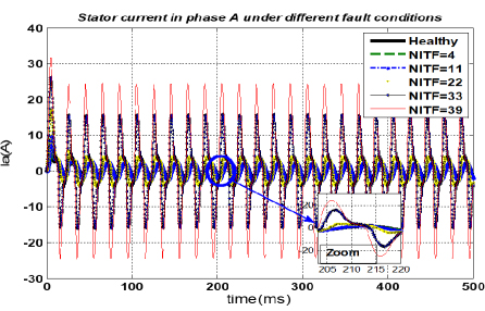
Figure 4: Stator currents of Phase A in healthy and unhealthy NITF conditions.
To further illustrate the impact of ITSCF on DFIG performances, four parameters, namely THD, THD%, RMS (root mean square) value, and peak value, are computed and analyzed. A comparative assessment is conducted between healthy and unhealthy operating conditions for each parameter. THD% is quantified for each fault condition as the ratio of the total harmonic content in the voltage waveform to its fundamental component. The computed results are presented in Table 4. The distortion level is computed using:
| (7) |
Peak value represents the absolute maximum magnitude of the current waveform during both the transient and steady-state operation.
Table 4 presents the computed parameters cited previously for Phase A under both healthy and unhealthy conditions with varying degrees of ITSCF, identified by the NITF.
Table 4: Analysis of stator current in Phase A under healthy and unhealthy conditions
| NITF | THD | THD% | RMS | Peak |
| Healthy | 0.043 | 4.37% | 1.54 | 4.97 |
| 4 | 0.050 | 5.08%. | 1.66 | 6.45 |
| 11 | 0.072 | 7.20% | 1.98 | 9.81 |
| 22 | 0.141 | 14.10% | 2.93 | 15.63 |
| 33 | 0.357 | 35.78% | 9.18 | 26.31 |
| 39 | 0.328 | 32.88% | 14.34 | 31.64 |
As observed in Table 4, the results indicate that THD increases substantially with fault severity, rising from 4.37% in the healthy condition to a peak of 35.78% at NITF33, before slightly decreasing to 32.88% at NITF39. This highlights a significant degradation in power quality as the fault becomes more severe. Similarly, the RMS current initially increases with the fault, reaching a critical value of 14.35 A at NITF39, compared to just 1.54 A in healthy conditions. Peak current values follow a similar trend, escalating from 4.97 A to 31.64 A, which can impose extreme stress on the winding insulation. This indicates severe waveform distortion and a significant rise in harmonic content, as illustrated in Fig. 4.
These results demonstrate clearly that increasing ITSCF severity leads to elevated current magnitudes, distorted waveforms, and significantly higher harmonic content, which can compromise the operational reliability and safety of the WECS if not promptly detected and mitigated.
B. FFT of stator currents of Phase A
Figure 5 shows the FFT comparison between a healthy case and various cases of NSWITSCF. We can see from Fig. 5 that the number of turns or short circuits directly influences the amplitude of the current. We can exploit this amplitude to make a diagnosis of the state of health of the machine.
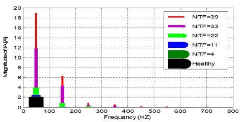
Figure 5: FFT of Phase A current in healthy and unhealthy NITF conditions.
C. Stator currents of Phases B and C
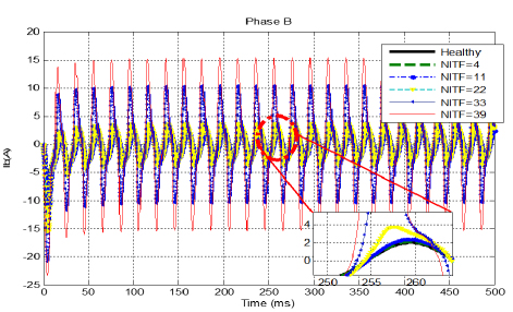
Figure 6: Stator currents of Phase B in healthy and unhealthy NITF conditions.
The impact of inter-turn faults in Phase A on the current in Phases B and C is depicted in Figs. 6 and 7. From these results, we can observe that their effects on the B and C phases are significant. We can see that in short-circuit situations where the current amplitude becomes more important, the system will become imbalanced with each increase in NITSCF.
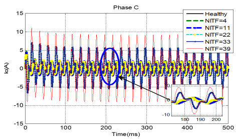
Figure 7: Stator currents of Phase C in healthy and unhealthy NITF conditions.
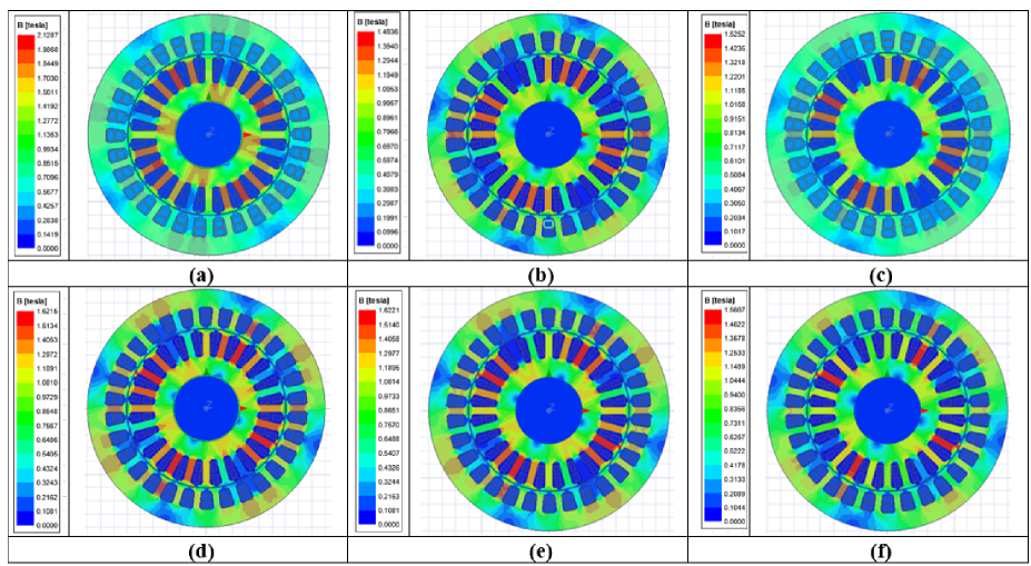
Figure 8: Magnetic field distribution for healthy and unhealthy DFIG in different cases of NSWITSCF: (a) Healthy, (b) 4 ITSCF, (c) 11 ITSCF, (d) 22 ITSCF, (e) 33 ITSCF, and (f) 39 ITSCF.
Table 5: Analysis of stator current in Phase B under healthy and unhealthy conditions in Phase A
| NITF | THD | THD% | RMS | Peak |
| Healthy | 0.054 | 5.42% | 1.70 | 7.94 |
| 4 | 0.054 | 5.43% | 1.80 | 8.92 |
| 11 | 0.058 | 5.84% | 2.04 | 11.11 |
| 22 | 0.141 | 14.10% | 2.93 | 15.63 |
| 33 | 0.298 | 29.85% | 6.31 | 20.88 |
| 39 | 0.302 | 30.24% | 9.18 | 23.52 |
Table 6: Analysis of stator current in Phase C under healthy and unhealthy conditions in Phase A
| NITF | THD | THD% | RMS | Peak |
| Healthy | 0.038 | 3.89% | 1.50 | 4.60 |
| 4 | 0.041 | 4.17% | 1.47 | 4.57 |
| 11 | 0.058 | 5.83% | 1.39 | 4.40 |
| 22 | 0.345 | 34.51% | 1.13 | 3.68 |
| 33 | 0.534 | 53.43% | 3.02 | 7.00 |
| 39 | 0.402 | 40.21% | 5.25 | 11.01 |
Tables 5 and 6 illustrate the impact of ITSCF on the current characteristics of Phases B and C in terms of THD, THD%, RMS, and Peak. For Phase B, THD increases from 5.42% in the healthy condition to 30.24% at the most severe fault condition. This is accompanied by a sharp rise in RMS current from 1.7 A to 9.18 A and peak current from 7.94 A to 23.52 A. Notably, Phase C is also affected by the ITSCF occurring in Phase A, exhibiting a similar response to that of Phase B, as shown in Table 6 and Fig. 7. THD escalates from 3.89% under normal operation to a maximum of 53.43% at NITF33, which is the highest among all three phases. RMS value rises from 1.50 A in the healthy case to 5.25 A for NITSF39, and peak current rises from 4.60 A to 11.01 A.
D. 2D distribution of magnetic flux density
Distribution of magnetic flux density is shown in Fig. 8 for both the normal case and various stator winding fault circumstances. It can be seen that both the stator and rotor areas have a strong magnetic field. Both rotor and stator leakage reactance will rise as a result. In certain areas, magnetic saturation will likewise rise. Due to the shift in current flowing through the rotor bars in the defective state, the generator’s torque will behaveasymmetrically.
V. CONCLUSION
The finite element method (FEM), often used for modeling and simulating electrical equipment, is a numerical method that enables the analysis of complicated and non-linear systems. Time-domain and frequency-domain representations of the stator currents as well as the magnetic flux density distribution under healthy and unhealthy conditions are compared for constant-speed operation. In this paper, we exploited the numeric computing power of FEM to simulate the healthy operation and several faulty operations in order to obtain a comparative analysis between the normal case and numerous cases of ITSCF for a single stator phase of DFIG. With a lesser increase in current in the B and C stator phases, ITSCF in the stator winding significantly increases branch current. The flux is reduced in Phase A of the stator winding as a result of SWITSCF, and the other two phases see less of a reduction. Moreover, when SWITSCF increases, the torque oscillates more and more. DFIG characteristics differ further from typical characteristics as there are more inter-turn short-circuits. This work can shed light on the consequences of SWITSCF, enabling the development of trustworthy fault detection and enhancing the quality of the electrical power that the DFIG wind turbines inject into the grid. To conclude, a bigger NSWITSCF generates a significant increase in faulty branch current, a current increase in all stator phases, and torque oscillation. As a research direction, it is important to extend the effects of the short circuit to the other quantities of the machine. It is important to do studies for a polyphase short circuit. It is important to take into account the effect of the rotation speed. It is important to use its results for diagnostics and fault location.
ACKNOWLEDGMENT
The authors would like to acknowledge the financial support received from the University of Setif-1 in Algeria the Research Project PRFU, under Grant (A01 L07 UN1901 2019 0002).
REFERENCES
[1] P. Veers, K. Dykes, E. Lantz, S. Barth, C. L. Bottasso, O. Carlson, A. Clifton, J. Green, P. Green, H. Holttinen, D. Laird, V. Lehtomäki, J. K. Lundquist, J. Manwell, M. Marquis, C. Meneveau, P. Moriarty, X. Munduate, M. Muskulus, J. Naughton, L. Pao, J. Paquette, J. Peinke, A. Robertson, J. S. Rodrigo, A. M. Sempreviva, J. C. Smith, A. Tuohy, and R. Wise, “Grand challenges in the science of wind energy,” Science, vol. 366, no. 6464, Oct. 2019.
[2] H. Mellah and K. E. Hemsas, “Design and analysis of an external-rotor internal-stator doubly fed induction generator for small wind turbine application by FEM,” Int. J. Sustain. Green. Energy, vol. 2, no. 1, p. 1, 2013.
[3] S. Dawn, P. K. Tiwari, A. K. Goswami, A. K. Singh, and R. Panda, “Wind power: Existing status, achievements and government’s initiative towards renewable power dominating India,” Energy Strateg. Rev., vol. 23, pp. 178-199, 2019.
[4] H. Mellah and E. K. Hemsas, “Design and simulation analysis of outer stator inner rotor DFIG by 2D and 3D finite element methods,” International Journal of Electrical Engineering Technology, vol. 3, no. 2, pp. 457-470, 2012.
[5] M. Fitouri, Y. Bensalem, and M. N. Abdelkrim, “Modeling and detection of the short-circuit fault in PMSM using finite element analysis,” IFAC-PapersOnLine, vol. 49, no. 12, pp. 1418-1423, 2016.
[6] J. Cheng, H. Z. Ma, S. Song, and Z. Xie, “Stator inter-turn fault analysis in doubly-fed induction generators using rotor current based on finite element analysis,” in Proceedings of the 2018 IEEE International Conference on Progress in Informatics and Computing (PIC 2018), pp. 414-419, Dec. 2018.
[7] A. U. Rehman, Y. Chen, Y. Zhao, Y. Cheng, Y. Zhao, and T. Tanaka, “Detection of rotor inter-turn short circuit fault in doubly-fed induction generator using FEM simulation,” in 2018 IEEE 2nd International Conference on Dielectrics (ICD), pp. 1-4, July 2018.
[8] H. Sabir, M. Ouassaid, and N. Ngote, “Diagnosis of rotor winding inter-turn short circuit fault in wind turbine based on DFIG using hybrid TSA/DWT approach,” in Proceedings of 2018 6th International Renewable and Sustainable Energy Conference, (IRSEC 2018), pp. 1-6, Dec. 2018.
[9] S. M. M. Moosavi, J. Faiz, M. B. Abadi, and S. M. A. Cruz, “Comparison of rotor electrical fault indices owing to inter-turn short circuit and unbalanced resistance in doubly-fed induction generator,” IET Electr. Power Appl., vol. 13, no. 2, pp. 243-250, 2019.
[10] H. Huangfu, Y. Zhou, J. Zhang, S. Ma, Q. Fang, and Y. Wang, “Research on inter-turn short circuit fault diagnosis of electromechanical actuator based on transfer learning and VGG16,” Electronics (Basel), vol. 11, no. 8, p. 1232, Apr. 2022.
[11] M. D. Xu, H. Li, and K. Shi, Microgrid for High-Surety Power: Architectures, Controls, Protection, and Demonstration. Boca Raton, FL: Taylor & Francis, 2017.
[12] J.-Q. Li and W. X.-M. Wang, “FEM analysis on interturn fault of rotor winding in DFIG,” in 2013 International Conference on Electrical Machines and Systems (ICEMS), pp. 797-802, Oct. 2013.
[13] E. Hamatwi, P. Barendse, and A. Khan, “Development of a test rig for fault studies on a scaled-down DFIG,” in 2021 IEEE Energy Conversion Congress and Exposition (ECCE), pp. 3805-3812, Oct. 2021.
[14] Q. F. Meng, Y. L. He, M. X. Xu, Y. Y. Zhang, and H. C. Jiang, “Effect of field winding inter-turn short-circuit positions on rotor ump of turbo-generator,” in ACM International Conference Proceeding Series, New York, NY, pp. 104-109,2018.
[15] H. Bilal, N. Heraud, and E. J. R. Sambatra, “An experimental approach for detection and quantification of short-circuit on a Doubly Fed Induction Machine (DFIM) windings,” J. Control Autom. Elec., vol. 32, no. 4, pp. 1123-1130, Aug. 2021.
[16] S. He, X. Shen, Y. Wang, and W. Zheng, “Characteristic factor analysis on stator winding inter-turn fault in DFIG Based on FEM simulation,” in Proceedings - 2017 International Conference on Computer Technology, Electronics and Communication (ICCTEC 2017), pp. 209-213, Dec. 2017.
[17] H. Benbouhenni, A. Driss, and S. Lemdani, “Indirect active and reactive powers control of doubly fed induction generator fed by three-level adaptive-network-based fuzzy inference system: Pulse width modulation converter with a robust method based on super twisting algorithms,” Electr. Eng. Electromechanics, no. 4, pp. 31-38, July 2021.
[18] S. V. Bozhko, R. V. Blasco-Giménez, R. Li, J. C. Clare, and G. M. Asher, “Control of offshore DFIG-based wind farm grid with line-commutated HVDC connection,” IEEE Trans. Energy Convers., vol. 22, no. 1, pp. 71-78, 2007.
[19] H. Benbouhenni and S. Lemdani, “Combining synergetic control and super twisting algorithm to reduce the active power undulations of doubly fed induction generator for dual-rotor wind turbine system,” Electr. Eng. Electromechanics, no. 3, pp. 8-17, 2021.
[20] X. Tian, H. Tang, Y. Li, Y. Chi, and Y. Su, “Dynamic stability of weak grid connection of large-scale DFIG based on wind turbines,” J. Eng., vol. 2017, no. 13, pp. 1092-1097, Jan. 2017.
[21] A. G. Abo-Khalil, W. Alharbi, A. R. Al-Qawasmi, M. Alobaid, and I. Alarifi, “Modeling and control of unbalanced and distorted grid voltage of grid-connected DFIG wind turbine,” Int. T. Electr. Energy, vol. 31, no. 5, May 2021.
[22] H. Ahmad, H. Khalid, A. A. Amin, N. Masroor, H. Mahmood, and M. Abubakar, “Improved current controlled doubly fed induction generator model with grid integration under sub and super synchronous conditions,” J. Electr. Eng. Technol., vol. 16, no. 1, pp. 141-153, Jan. 2021.
[23] S. R. Kabat and C. K. Panigrahi, “Fuzzy logic and synchronous reference frame controlled LVRT capability enhancement in wind energy system using DVR,” Turk. J. Comput. Math. Educ., vol. 12, no. 6, pp. 4899-4907, June 2021.
[24] H. Mellah, S. Arslan, H. Sahraoui, K. E. Hemsas, and S. Kamel, “The effect of stator inter-turn short-circuit fault on DFIG performance using FEM,” Eng. Technol. Appl. Sci. Res., vol. 12, no. 3, pp. 8688-8693, June 2022.
[25] O. Imoru, F. V. Nelwamondo, A. Jimoh, and T. R. Ayodele, “A neural network approach to detect winding faults in electrical machine,” Int. J. Emerg. Electr. P., vol. 22, no. 1, pp. 31-41, Feb. 2021.
[26] Y. Chen, A. U. Rehman, Y. Zhao, L. Wang, S. Wang, M. Zhang, Y. Zhao, Y. Cheng, and T. Tanaka, “Numerical modeling, electrical characteristics analysis and experimental validation of severe inter-turn short circuit fault conditions on stator winding in DFIG of wind turbines,” IEEE Access, vol. 9, pp. 13149-13158, 2021.
[27] J. Cheng, H. Z. Ma, S. Song, and Z. Xie, “Stator inter-turn fault analysis in doubly-fed induction generators using rotor current based on finite element analysis,” in Proceedings of the 2018 IEEE International Conference on Progress in Informatics and Computing (PIC 2018), pp. 414-419, Dec. 2018.
[28] S. He, X. Shen, and Z. Jiang, “Detection and location of stator winding interturn fault at different slots of DFIG,” IEEE Access, vol. 7, pp. 89342-89353, 2019.
[29] K. Ma, J. Zhu, M. Soltani, A. Hajizadeh, and Z. Chen, “Inter-turn short-circuit fault ride-through for DFIG wind turbines,” IFAC-PapersOnLine, vol. 53, no. 2, pp. 12757-12762, 2020.
[30] F. Bouaziz, O. Awedni, and L. Krichen, “Modelling and fault diagnosis of rotor inter turn short circuit fault in a doubly fed induction generator-based wind turbine,” in Proceedings 20th International Conference on Sciences and Techniques of Automatic Control and Computer Engineering, pp. 189-194, Dec. 2020.
[31] Z. Tan, X. Song, W. Cao, Z. Liu, and Y. Tong, “DFIG machine design for maximizing power output based on surrogate optimization algorithm,” IEEE Trans. Energy Convers., vol. 30, no. 3, pp. 1154-1162, 2015.
[32] V. K. Sharma and L. Gidwani, “Steady-state analysis of permanent magnet synchronous generator with uncertain wind speed,” Adv. Intel. Syst. Comput., vol. 697, pp. 253-261, 2019.
[33] I. Gómez, G. García, A. McCloskey, and G. Almandoz, “Analytical model to calculate radial forces in permanent-magnet synchronous machines,” Appl. Sci., vol. 11, no. 22, p. 10865, Nov. 2021.
[34] Z. Xing, Y. Gao, M. Chen, and J. Xu, “Fault diagnosis of inter-turn short circuit of permanent magnet synchronous wind turbine under the random wind,” in 2021 IEEE 2nd China International Youth Conference on Electrical Engineering (CIYCEE), pp. 1-6, Dec. 2021.
[35] Z. T. Mei, G. J. Li, Z. Q. Zhu, R. Clark, A. Thomas, and Z. Azar, “Scaling effect on inter-turn short-circuit of PM machines for wind power application,” in 2021 IEEE International Electric Machines & Drives Conference (IEMDC), pp. 1-8, May 2021.
[36] R. Palka and M. Wardach, “Design and application of electrical machines,” Energies (Basel), vol. 15, no. 2, p. 523, Jan. 2022.
[37] L. Jun-Qing, M. A. Li, and W. De-Yan, “Influence of stator turn-to-turn short-circuit on magnetic field of DFIG,” in 2011 International Conference on Electrical Machines and Systems (ICEMS 2011), pp. 1-5, Aug. 2011.
[38] Y. Chen, L. Wang, Z. Wang, A. U. Rehman, Y. Cheng, Y. Zhao, and T. Tanaka, “FEM simulation and analysis on stator winding inter-turn fault in DFIG,” in 2015 IEEE 11th International Conference on the Properties and Applications of Dielectric Materials (ICPADM), pp. 244-247, July 2015.
[39] P. Han, M. Cheng, Z. Zhang, and P. Peng, “Spiral vector modeling of brushless doubly-fed induction machines with short-circuited rotor windings,” Chinese J. Electr. Eng., vol. 7, no. 3, pp. 29-41, Sep. 2021.
[40] Z. T. Mei, G. J. Li, Z. Q. Zhu, R. Clark, A. Thomas, and Z. Azar, “Scaling effect on inter-turn short-circuit of PM machines for wind power application,” in 2021 IEEE International Electric Machines & Drives Conference (IEMDC), pp. 1-8, May 2021.
[41] S. He, X. Shen, and Z. Jiang, “Detection and location of stator winding interturn fault at different slots of DFIG,” IEEE Access, vol. 7, pp. 89342-89353, 2019.
[42] M. Afshari, S. M. M. Moosavi, M. B. Abadi, and S. M. A. Cruz, “Study on inter-turn short circuit fault and high resistance connection in the stator of doubly-fed induction generators,” in 7th Iran Wind Energy Conference (IWEC2021), pp. 1-6, May 2021.
[43] Y. Fu, Z. Ren, S. Wei, Y. Xu, and F. Li, “Using flux linkage difference vector in early inter-turn short circuit detection for the windings of offshore wind DFIGs,” IEEE Trans. Energy Convers., vol. 36, no. 4, pp. 3007-3015, Dec. 2021.
[44] H. C. Dirani, A. Merkhouf, B. Kedjar, A. M. Giroux, and K. Al-Haddad, “Finite element simulation of hydro generators with rotor inter turn short circuit,” in 2017 IEEE International Electric Machines and Drives Conference (IEMDC 2017), pp. 1-6, May 2017.
[45] H. Mellah and K. E. Hemsas, “Simulations analysis with comparative study of a PMSG performances for small WT application by FEM,” International Journal of Energy Engineering, vol. 3, no. 2, pp. 55-64, 2013.
[46] A. Petersson, “Analysis, modeling and control of doubly-fed induction generators for wind turbines,” Thesis for the Degree of Doctor of Philosophy, Department of Energy and Environment, Chalmers University of Technology, Goteborg, Sweden, 2005.
BIOGRAPHIES

Hacene Mellah received the B.S. (2006), Magister (2009), and Ph.D. (2020) degrees from Sétif 1 University, Algeria. Since 2020, he has been an Associate Professor at the University of Bouira. His research interests include control and diagnostics of electrical machines, intelligent techniques, and renewable energy.

Amar Maafa received the B.S. (2008) and Ph.D. (2017) degrees in Electrical Engineering from the University of Bejaia, Algeria, and a Magister degree from Batna University in 2011. His research focuses on control, modelling, and diagnostics of wind energy conversion systems.

Hamza Sahraoui has a Ph.D. in Industrial Systems Control and Renewable Energy (2016, Batna 2 University, Algeria). Currently he is an Associate Professor. His research focuses on control systems, nonlinear and adaptive control, and renewable energy.

Abdelghani Yahiou received the B.Eng. (2009), M.Sc. (2012), and Ph.D. (2021) degrees in Electrical Engineering from the University of Setif-1, Algeria. Currently he is an Associate Professor. His research interests include transformer transients, inrush current, ferroresonance, modelling, and measurement systems.

Souhil Mouassa received the Ph.D. from Universidad de Jaén, Spain, and Sétif 1 University, Algeria, in 2021. His research interests include optimal power system planning and operation, power system optimization, microgrids planning and operation, renewable energy sources, demand-side management, and smart homes.

K. E. Hemsas received his Engineering (1991), Magister (1995), and Doctorate (2005) degrees from the University of Sétif 1, Algeria. He is a Full Professor in the Department of Electrical Engineering. His research interests include power quality, modelling, control and diagnosis of electrical machines, renewable energy, and artificial intelligence.
ACES JOURNAL, Vol. 40, No. 7, 651–660
doi: 10.13052/2024.ACES.J.400709
© 2025 River Publishers