Fast Broadband Scattering Computation for Finite Periodic Arrays using the Characteristic Basis Function Method and the Best Uniform Rational Approximation
Fang Li, Hai Rong Zhang, Lin Chen, and Xing Wang
1Antenna and RF Specialist Department
20th Research Institute of China Electronics Technology Group Corporation, Xi’an, Shaanxi 710068, China
kleelf@163.com
2Department of Electrical and Computer Engineering
Xi’an, Shaanxi 710071, China
m15592666916@163.com, linchen3@stu.xidian.edu.cn, wangxing@mail.xidian.edu.cn
Submitted On: January 16, 2024; Accepted On: July 11, 2024
ABSTRACT
In this paper, a hybrid method combining the characteristic basis function method (CBFM) and the best uniform rational approximation (BURA) technique for fast wideband radar cross-section (RCS) prediction of finite periodic arrays is proposed. The traditional CBFM requires reconstructing the reduced matrix at each frequency point, which is very time-consuming when calculating the wideband RCS of the target. By introducing the BURA technique, the hybrid method is proposed to efficiently calculate the wideband RCS. The target is first divided into several easily solvable subdomains. Then, the surface integral equation is solved by the characteristic function method to obtain the equivalent surface current at the Chebyshev node. Afterwards, the surface current in a desired frequency band is represented by the Chebyshev series. To improve accuracy, the Chebyshev series is matched with the Maehly approximation. After obtaining the current coefficients in the whole bandwidth, the current density at any frequency point in the bandwidth can be calculated. Finally, the broadband electromagnetic scattering characteristics of the finite periodic arrays can be obtained.
Index Terms: best uniform rational approximation, broadband, characteristic basis function method, Maehly approximation.
I. INTRODUCTION
In recent years, typical periodic structures such as frequency-selective surfaces, electromagnetic bandgap structures and metamaterial structures have been widely analyzed and applied. These structures are often electrically large and have complex electromagnetic properties that vary with frequency and other parameters. The analysis of these structures may require further refinement of the mesh. Both of them will lead to a large amount of the number of unknowns.
To address the above problems, many methods have been proposed [1][2]. One is the traditional Method of Moments (MoM) [3], which is extremely expensive in terms of computational resources when dealing with electrically large problems. The multilayer fast multipole method (MLFMA) [4][5] and the adaptive cross approximation (ACA) algorithm [6][7] have both been proposed to address this problem. These algorithms can improve the computational efficiency of MoM, but they require the use of an iterative method for solving. Therefore, there is a problem of slow convergence or even failure to converge when dealing with complex objectives. A second class of methods is to reduce the impedance matrix dimension by constructing basis functions, such as the sub-entire domain basis functions [8] and the characteristic basis function method (CBFM) [9][10]. These methods reduce the impedance matrix scale and decrease the number of unknowns for the target. The method first divides the objective into several subdomains. Then different subdomain sizes can be selected to control the dimension of the impedance matrix according to the requirements. Finally, the weighting coefficients of the characteristic basis functions can be obtained by solving the impedance matrix in low dimensions by the direct method. The stability and computational efficiency of the solution are guaranteed.
However, when utilizing CBFM to obtain the target broadband RCS the impedance matrix must be filled repetitively at each frequency point, leading to a large amount of computational time. In recent years, fast computational methods such as the impedance matrix interpolation method, the Cauchy method, the best uniform rational approximation (BURA) [11][12], model parameter estimation (MBPE) [13][14] and asymptotic waveform estimation (AWE) [15–18] have been proposed. Among them, BURA has been widely used. It has the advantages of good convergence, easy integration with CBFM and no need to increase memory. When using BURA the process of repeated solutions of matrix equations can be bypassed, which reduces the computation time of the impedance matrix.
The remainder of this paper is organized as follows. The formulations of the Chebyshev approximation technique (CAT) application to CBFM are explicitly derived in Section II. Three examples are presented in Section III to verify the accuracy and efficiency of the hybrid CBFM-CAT algorithm and the conclusion of this work is drawn in Section IV.
II. CBFM-CAT FORMULATION
In solving the broadband electromagnetic characteristics of periodic structures, CBFM is utilized to solve the large unknown matrix during computation. However, for broadband RCS calculations, CBFM still needs to calculate the surface currents at each frequency, which leads to a large amount of computation time. By introducing the idea of CAT, the hybrid CBFM-CAT implements to achieve fast frequency sweeping as follows.
The electric field integral equation (EFIE) can be written as:
| (1) |
where denotes impedance matrix, denotes current coefficient vector and denotes excitation vector.
CBFM divides the target into N subdomains . According to CBFM, the matrix equation of equation (1) can be written as:
| (2) |
When , is the self-impedance matrix of region . When, is the mutual impedance matrix of region and region . is the matrix of current coefficients of region , is the excitation vector of region and .
Uniform plane wave illuminates each subdomain, the frequency range, the corresponding wave number is . Using the coordinate transformation, is obtained by:
| (3) |
Let be a Chebyshev polynomial of order defined as follows:
| (4) |
Then the q-th Chebyshev node of the Q order Chebyshev polynomial can be calculated by equation (5):
| (5) |
To transform from interval into interval , the q-th Chebyshev frequency sampling point in band can be obtained by using equation (6):
| (6) |
Afterwards, the induced current at the Chebyshev frequency sampling point in the -th subdomain is obtained. Assume that the number of discrete units in the subdomain before expansion is and after expansion is . Then the main characteristic basis functions of the extended subdomain can be derived from:
| (7) |
where is a matrix, the matrix corresponding to the extended subdomain in the excitation vector from equation (2). is the self-impedance matrix of the extended subdomain, which is an -dimensional square matrix. By performing the LU decomposition of followed by matrix inversion, the main characteristic basis functions of the extended subdomain can be derived from equation (7).
According to the Foldy-Lax multipath scattering equation, the total characteristic basis function for constructing a periodic structure target should include the primary characteristic basis function (PCBF), which represents the self-interaction of the subdomains themselves. The secondary characteristic basis function (SCBF) represents the interaction between the subdomains. The primary secondary feature basis function can be used as an excitation source by superimposing the primary feature basis function on the remaining subfields. The surface induced current is generated in the desired subregion. The primary characteristic basis function has been derived from equation (7), at which point the secondary characteristic basis function can be derived from:
| (8) |
can be obtained by a direct inverse of the LU decomposition of via equation (8). Similarly, the secondary characteristic basis functions of the remaining subdomain targets can be derived. If the secondary characteristic basis functions are taken only up to , the total induced current on each subdomain target can be written as:
| (9) |
The dimensionality of the impedance matrix can be reduced by Galerkin method. By obtaining the unknown coefficients and , the induced currents on a total of N subdomains can be obtained. Then the target surface current coefficients for each subdomain are .
To improve the accuracy of the numerical solution, the Chebyshev series is replaced by a rational function named Maehly approximation. The surface current in the -th subdomain can be approximated as:
| (10) |
where .
To improve the accuracy of the numerical solution, using the Maehly approximation to obtain the current coefficient vector, can be re-expressed as:
| (11) |
where denotes the first unknown coefficient of the -th subdomain at the Chebyshev node of the Chebyshev polynomial of order , and denotes the second unknown coefficient of the -th subdomain at the Chebyshev node of the Chebyshev polynomial of order, .
Substituting equation (12) into equation (11) and using the constant equation , the unknown coefficients and can be obtained as follows:
| (12) |
| (13) |
Calculating the unknown coefficients and for the -th subdomain , the surface current can be obtained by using and and substituting them into equation (11) thereby obtaining the radar scattering cross section of the periodic structure target at each frequency.
The error function is defined as:
| (14) |
The coefficient in equation (14) can be defined as:
| (15) |
Since is usually set to 1, the coefficient decays rapidly then the error function can be approximated as:
| (16) |
where:
| (17) |
Hence, can be taken as BURA to .
III. NUMERICAL SIMULATION RESULTS AND ANALYSIS
A. A 9x9 patch array
The first example is a 99 patch array consisting of square ring frequency selective cells with a center frequency of 15 GHz, as illustrated in Fig. 1. The incident angle is (inc, inc)(0, 0) and the scattering angle is (sca, sca)(60, 0). The working frequency band is 12 to 20 GHz. The step frequency is 100 MHz. The whole structure can be decomposed into four subdomains with a total of 3402 unknowns for the target. The unknowns for each sub-domain are 756, 756, 756 and 1134 when using CBFM, respectively. The broadband RCS of the target was calculated by using the Chebyshev approximation with the Maehly approximation (LM3, LM7, LM15).
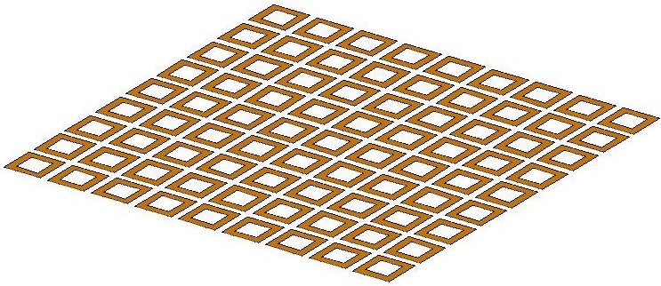
Figure 1: Geometry of the patch array.
Figure 2 illustrates the broadband bistatic cross-section (BCS) of the patch array in the 12-20 GHz range using three different CBFM-CAT orders (L=3, 7, 15). A results comparison between the CBFM-CAT algorithm and the conventional moments method can be seen in Fig. 2. Better results will be obtained as we increase the CAT order.
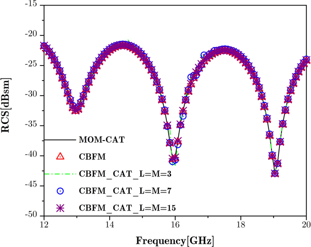
Figure 2: Wideband BCS of the patch array computed by CBFM-CAT using three different orders.
As shown in Fig. 3, the peak memory, CPU time and the number of iterations of MoM, CBFM and CBFM-CAT with three orders are compared. According to Fig. 3, total CPU time of CBFM-CAT (L=M=15) can be reduced by 54.4% compared to conventional MoM.
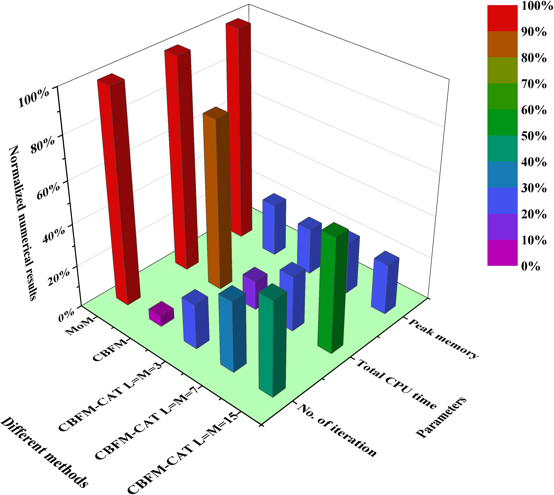
Figure 3: Comparation of peak memory, CPU time and number of iterations for conical radome.
B. Square-ring FSS conical radome
The second example is a six-layer conical FSS radome consisting of a square-ring type frequency selector unit with a center frequency of 15 GHz, as illustrated in Fig. 4. The incident angle is (, )=(0, 0) and the scattering angle is (, )=(60, 0). The working frequency band is 12 to 20 GHz. The step frequency is 100 MHz. The whole structure can be decomposed into three subdomains with a total of 3234 unknowns for the target. The unknowns for each subdomain are 1386, 1134 and 714 when using CBFM, respectively. The broadband RCS of the target was calculated using the Chebyshev approximation with the Maehly approximation (L=M=3, L=M=7, L=M=15).
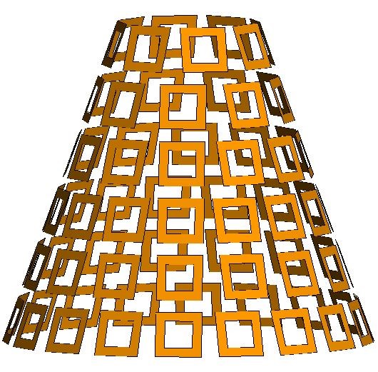
Figure 4: Geometry of the square ring FSS conical radome.
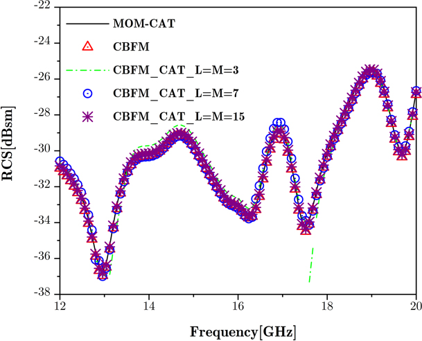
Figure 5: Wideband BCS of conical radome computed by CBFM-CAT using three different orders.
Figure 5 illustrates the broadband BCS of the conical radome in the 12-20 GHz range using three different CBFM-CAT orders (L3, 7, 15). Figure 5 shows that the results obtained by the CBFM-CAT algorithm are in good agreement with the traditional MoM. As we increase the order of CAT we get a better result.
As shown in Fig. 6, peak memory, CPU time and number of iterations of MoM, CBFM and CBFM-CAT with three orders are compared. According to Fig. 6, the computation time of CBFM-CAT (LM15) can be reduced by 54.7% compared to conventional MoM.
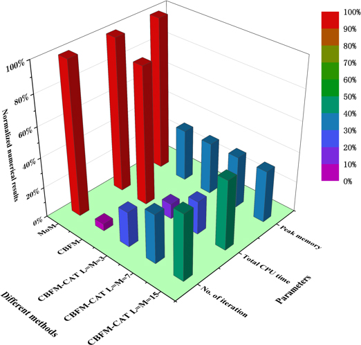
Figure 6: Comparation of peak memory, CPU time and number of iterations for conical radome.
C. Square-ring FSS pyramid radome
The third example we consider is an FSS pyramid radome composed of a square-ring frequency selector unit with a center frequency of 15 GHz, as shown in Fig. 7. The model is divided into four subdomains. The FSS pyramid radome is discretized into 3136 elements so that the number of unknowns is 4704. The unknowns for each subdomain when using CBFM are 1176, 1176, 1176, 1176 and 1176. The incident angle is (, )=(0, 0) and the scattering angle is (, )=(60, 0). The working frequency band is 12 to 20 GHz. Step frequency is 100 MHz.
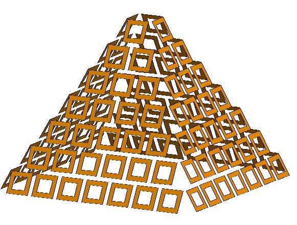
Figure 7: Geometry of the square ring FSS pyramid radome.
The broadband RCS of the target was calculated using the Chebyshev approximation with the Maehly approximation (LM3, LM7, LM15). Figure 8 shows that the results obtained by the CBFM-CAT algorithm are in good agreement with traditional MoM. As the order of CAT increases, better results are obtained. The results obtained by CBF M-CAT are consistent with those obtained by MoM and CBFM.
Table 1: Calculation result of three examples
| Examples | MoM CPU Time (min) | CBFM (L=M=15) CPU Time (min) | MoM Memory (MB) | CBFM (L=M=15) Memory (MB) |
| Array patch | 92.56 | 53.7 | 124.32 | 34.27 |
| Conical radome | 72.45 | 33.5 | 80.64 | 27.64 |
| Pyramid radome | 126.1 | 69.9 | 168.96 | 42.41 |
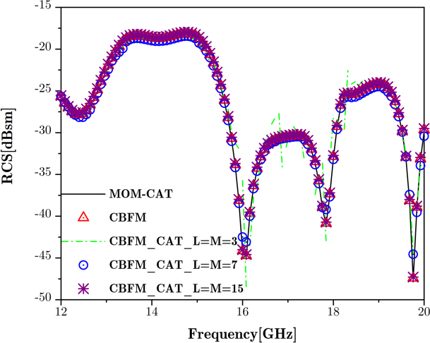
Figure 8: Broadband BCS of the pyramid radome computed by CBFM-CAT using three different orders.
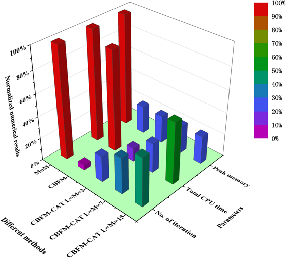
Figure 9: Comparation of peak memory, CPU time and number of iterations for pyramid radome.
As shown in Fig. 9, peak memory, CPU time and number of iterations of MoM, CBFM and CBFM-CAT with three orders are compared. According to Fig. 9, the total CPU time of CBFM-CAT (L=M=15) can be reduced by 45.6% compared to conventional MoM.
Table 1 illustrates the total memory and CPU time required to compute the three examples by using MOM and CBFM methods. In comparison to traditional MoM, the memory requirement and CPU time of CBFM-CAT can achieve reduction for the three examplesshown.
IV. CONCLUSION
In this paper, we propose a new hybrid CBFM-CAT algorithm to efficiently analyze the wideband electromagnetic bistatic scattering problem for finite periodic arrays. By applying CBFM, the dimensionality of the impedance matrix can be reduced. By introducing the idea of CAT, only the currents at the Chebyshev nodes are calculated. The surface current in a desired frequency band is represented by a Chebyshev series by combining it with the Maehly approximation. After obtaining the current coefficients over the entire broadband, we can then obtain the current density at any frequency point. Furthermore, we discuss the accuracy of the CBFM-CAT method at different orders. According to the numerical results, the proposed CBFM-CAT method is able to significantly improve efficiency with a slight loss of accuracy.
ACKNOWLEDGMENT
This work was supported in part by the National Natural Science Foundation of China (Grant 62471365, Grant 62271366, Grant 62394293, and Grant 62394290), the Fundamental Research Funds for the Central Universities (grant no. ZDRC210).
REFERENCES
[1] K. Niu, Z. J. Xiao, G. Xie, X. G. Ren, Y. S. Li, Z. X. Huang, X. L. Wu, and A. Z. Elsherbeni, “A stochastic FDTD algorithm for uncertainty quantification of electromagnetic-thermal simulation,” IEEE Trans. Microw. Theory Techn., vol. 72, no. 7, pp. 3935-3946, July 2024.
[2] G. Zhu, K. Niu, M. Q. Li, Y. S. Li, X. G. Ren, G. D. Xie, Z. X. Huang, X. L. Wu, and A. Z. Elsherbeni, “High-order ME-CFS-PML implementations for terminating the FDTD domain composed of arbitrary media,” IEEE Trans. Microw. Theory Techn., vol. 72, no. 4, pp. 2414-2426, Oct. 2023.
[3] R. F. Harrington and J. L. Harrington, Field Computation by Moment Methods. Oxford: Oxford University Press, 1996.
[4] J. Song, “Multilevel fast multipole algorithm for electromagnetic scattering by large complex objects,” IEEE Trans. Antennas Propag., vol. 45, no. 10, pp. 1488-1493, 2002.
[5] C. B. Wu, L. Guan, P. F. Gu, and R. S. Chen, “Application of parallel CM-MLFMA method to the analysis of array structures,” IEEE Trans. Antennas Propag., vol. 69, no. 9, pp. 6116–6121, Sep. 2021.
[6] K. Zhao, M. N. Vouvakis, and J.-F. Lee, “The adaptive cross approximation algorithm for accelerated method of moments computations of EMC problems,” IEEE Trans. Electromagn. Compat., vol. 47, no. 4, pp. 763-773, Nov. 2005.
[7] M. Bebendorf, “Approximation of boundary element matrices,” Numer. Math., vol. 86, no. 4, pp. 565-589, June 2000.
[8] X. Wang, D. H. Werner, and J. P. Turpin, “A fast analysis of scattering from large-scale finite periodic microstrip patch arrays arranged on a non-orthogonal lattice using sub-entire domain basis functions,” IEEE Trans. Antennas Propag., vol. 62, no. 5, pp. 2543-2552, 2014.
[9] E. Garc’1a, C. Delgado, and F. C’atedra, “Efficient iterative analysis technique of complex radome antennas based on the characteristic basis function method,” IEEE Trans. Antennas Propag., vol. 69, no. 9, pp. 5881-5891, Sep. 2021.
[10] C. Li, M. S. Sharawi, and R. Mittra, “Fast computation of electromagnetic scattering from dielectric objects using quadrilateral piecewise sinusoidal basis and characteristic basis function method,” IEEE Trans. Antennas Propag., vol. 70, no. 7, pp. 5683-5692, July 2022.
[11] J. Ling, S. X. Gong, X. Wang, B. Lu, and W. T. Wang, “A novel two-dimensional extrapolation technique for fast and accurate radar cross section computation,” IEEE Antennas Wireless Propag. Lett., vol. 9, pp. 244-247, 2010.
[12] X. Wang, S. Zhang, H. Xue, S. X. Gong, and Z. L. Liu, “A Chebyshev approximation technique based on AIM-PO for wide-band analysis,” IEEE Antennas Wireless Propag. Lett., vol. 15, pp. 93-97,2016.
[13] Z. Wang and S. V. Hum, “A broadband model-based parameter estimation method for analyzing multilayer periodic structures,” IEEE Trans. Antennas Propag., vol. 69, no. 9, pp. 5771-5780, Sep. 2021.
[14] X. Wang, D. H. Werner, and J. P. Turpin, “Application of AIM and MBPE techniques to accelerate modeling of 3-D doubly periodic structures with nonorthogonal lattices composed of bianisotropic media,” IEEE Trans. Antennas Propag., vol. 62, no. 8, pp. 4067-4080, Aug. 2014.
[15] C. J. Reddy, M. D. Deshpande, C. R. Cockrell, and F. B. Beck, “Fast RCS computation over a frequency band using method of moments in conjunction with asymptotic waveform evaluation technique,” IEEE Trans. Antennas Propag., vol. 46, no. 8, pp. 1229-1233, Aug. 1998.
[16] X. Wang, S. X. Gong, J. L. Guo, Y. Liu, and P. F. Zhang, “Fast and accurate wide-band analysis of antennas mounted on conducting platform using AIM and asymptotic waveform evaluation technique,” IEEE Trans. Antennas Propag., vol. 59, no. 12, pp. 4624-4633, Dec. 2011.
[17] Y. L. Jiang and J. M. Yang, “Asymptotic waveform evaluation with higher order poles,” IEEE Trans. Circuits Syst. I, Reg. Papers, vol. 68, no. 4, pp. 1681-1692, Apr. 2021.
[18] M. A. M. Hassan and A. A. Kishk, “A combined asymptotic waveform evaluation and random auxiliary sources method for wide-band solutions of general-purpose EM problems,” IEEE Trans. Antennas Propag., vol. 67, no. 6, pp. 4010-4021, June 2019.
BIOGRAPHIES

Fang Li was born in Shaanxi, China, in 1982. He received the M.Eng. Degree in electronic engineering from Xidian University, Xi’an, China, in 2008. Currently, he is with the 20th Research Institute of China Electronics Technology Group Corporation, Xi’an 710065, China. His research interests include antenna RCS reduction, wideband antenna and metasurface.

Hai Rong Zhang was born in Shaanxi, China, in 1996. He received the B.Eng. degree in electronic engineering from Xidian University, Xi’an, China, in 2019, where he is currently working toward the Ph.D. degree. His research interests include computational electromagnetic, hybrid methods and multiscale electromagnetic computing.
Lin Chen was born in Hunan, China, in 2000. He received the B.Eng. degree in electronic engineering from Xidian University, Xi’an, China, in 2022. His focus is computational electromagnetic.

Xing Wang received the Ph.D. degree from Xidian University, Xi’an, China, in 2011. His research interests include computational electromagnetic, fast algorithms for electromagnetic scattering and radiation, hybrid methods and EMC analysis.
ACES JOURNAL, Vol. 39, No. 10, 848–854
doi: 10.13052/2024.ACES.J.391001
© 2024 River Publishers