Analysis and Simulations of Electrothermal Characteristics of Water-based Ultrawideband Absorber Using HIE-FVM Hybrid Method
Wen Bin Yan, Yi Wang, and Qun Sheng Cao
College of Electronic and Information Engineering, Nanjing University of Aeronautics and Astronautics
Nanjing, 21000, China
yanwebin4721@163.com, jflsjfls@nuaa.edu.cn, qunsheng@nuaa.edu.cn
Submitted On: January 30, 2024; Accepted On: September 13, 2024
ABSTRACT
In this study, the dispersion characteristics, impedance features, and absorption conditions of water-based electromagnetic (EM) absorbers are investigated. A methodology for the rapid construction of a three-layer water-based absorber structure is proposed. Concurrently, a weakly conditionally stable Hybrid Implicit-Explicit Finite Difference Time Domain (HIE-FDTD) method is introduced to enhance the computational efficiency of thin layer structures. Furthermore, the EM computation integrates thermal effect calculations. A hybrid approach, combining the HIE-FDTD and Finite Volume Method (FVM), is employed to analyze temperature variations induced by EM wave incidence on the absorber.
Index Terms: Electrothermal coupling computation, FVM, HIE-FDTD, Water-based absorber.
I. INTRODUCTION
Water-based absorbers are a unique type of absorptive structure that utilizes the inherent properties of water to attenuate EM waves. Because of their distinctive nature, these absorbers showcase significant potential in applications such as stealth technology and EM susceptibility (EMS) shielding. Their primary advantages include tunability [1], multi-band and broadband absorption capabilities [2, 3], and flexibility [4]. However, this structure also faces some challenges. For instance, the physical properties of water are easily affected by temperature changes, which can lead to performance inconsistencies. Ensuring stable performance under various environmental conditions, such as temperature fluctuations, humidity changes, and atmospheric pressure variations, remains the primary concern.
The Finite-Difference Time-Domain (FDTD) method [5, 6] is a widely adopted numerical technique used to solve EM problems, such as electromagnetic-thermal coupling and dispersive media calculations [7, 8]. The Hybrid Implicit-Explicit Finite Difference Time Domain (HIE-FDTD) approach augments the conventional FDTD methodology by using both implicit and explicit schemes [9, 10, 11]. Its hybrid nature introduces a conditionally weak stability, permitting a more extensive time step size compared to the traditional explicit FDTD method, thereby accelerating computational speed in simulations. This method exhibits computational advantages particularly when analyzing thin layered structures.
With the growing attention to electrothermal coupling issues, the traditional practice of conducting EM simulations and thermal simulations independently is being re-evaluated . As the complexity of the problems being addressed increases, and the demand for solution accuracy intensifies, joint electrothermal solutions are emerging as a trend. Thermal effects, leading to material alterations, subsequently influence the EM response, which in turn affects the temperature distribution , forming a multi-physics computational loop. It is applied in multiple fields, such as electromagnetic-thermal analysis of absorbing structures [12], thermal-electric losses in circuits [13], material phase change at microwave frequencies [14], and electromagnetic-thermal calculations in dispersive media [15].
This paper initially investigates the fundamental principles of water-based absorbers and presents a broadband absorption structure based on absorption criteria, computed using the HIE-FDTD method. Subsequently, the temperature distribution and its impact on EM wave absorption performances are elucidated through electrothermal coupling calculations.
II. THEORETICAL ANALYSIS
A. HIE method and heat transfer calculation
In this section, we introduce the HIE-FDTD method and the associated update formulas for the calculation of EM fields. Many articles have already provided detailed derivation steps and proofs [10, 11]. This paper presents a simplified derivation process to demonstrate the characteristics of the method. This method is distinguished by its manipulation of the update time steps for magnetic and electric fields, which leads to implicit updates for specific field components, while preserving explicit updates for one component. Herein, we adopt the notation means . Then, the update equations for the HIE can be derived:
| (1) | |
| (2) | |
where , , and denote the spatial discretization steps along the x, y, and z directions, respectively. is permittivity in the z direction, and are permeability in the x and y directions. This method places the time steps for both and at the position, while the remaining components are positioned at the time step. It results in a lack of uniformity in the time step values for the and components but this discrepancy can be addressed by taking the average with an implicit solving step, which requires simultaneous resolution at the time step. By substituting Eq. (2.1) into (2.1), a tridiagonal matrix is derived, which can be solved using the TDMA method as equation (2.1) and (4). are the sum of EM values of available present step:
| (3) | |
where:
| (4) | ||
The advantages of this method include the relaxation of stability constraints. It is highly efficient when using finely detailed spatial grid divisions in specific directions, such as in the calculation of thin-layer structures. Additionally, this method requires fewer tridiagonal matrix solutions, leading to an improvement in overall efficiency.
| (5) |
As depicted in equation (5), is the speed of EM wave propagation in free space and, compared to the conventional FDTD method, the stability condition of HIE-FDTD eliminates the need to consider the spatial step in the x-direction, allowing for a larger time step selection. Furthermore, when solving EM computational problems, we also consider the thermal effects generated in the material when EM waves incident on the target. Then, the simulation problem of a single EM phenomenon becomes a multi-physics solving problem. The thermal conduction equation is given as follow [15]:
| (6) |
where, represents specific heat capacity, stands for density, denotes thermal conductivity, signifies an additional heat source, and represents an acceleration factor. The acceleration factor increases the thermal property parameters, speeding up the heat conduction process and causing more temperature changes in shorter time steps. This method aims to correlate significantly different electromagnetic simulation times with thermal simulation times, enabling simultaneous computational programming. In the absence of acceleration factors, the Finite Volume Method (FVM) form of equation (6) is:
| (7) | |
Equation (2.1) presents the expression for the FVM method post-discretization. As observed from equation (2.1), the differential form of the FVM method bears a strong resemblance to the FDTD method, suggesting the feasibility of employing a unified grid partitioning scheme for analysis. An important aspect of integrating EM and thermal processes is to treat the resulting EM losses as new heat sources [16]. The EM field energy can be obtained through Poynting theorem as follows:
| (8a) | |
| (8b) | |
| (8c) | |
From equation (8), it is noted that the energy loss in the EM field is given by . In addition, based on the characteristics of Debye dielectric, its energy loss can be derived [16]. The sum of these two losses constitutes the heat source term in equation (8c), thereby conducting EM thermal multi-physics computations.
B. Absorption rate computation of water-based absorber
For reflective EM absorbers, the absorption function can be studied by investigating whether the impedance generated by the combination of multi-layer materials or structures meets the absorption criteria. The same research approach can also be applied to the study of water-based absorbers. Figure 1 is shown the schematic diagram of the absorber structure, , , and are the thickness of three media layers. Here, and are conventional dielectric materials, and is the water layer. , , and are the corresponding impedance values. According to the transmission line theory, the input impedance of each layer can be calculated using the following formulas:
| (9) | ||
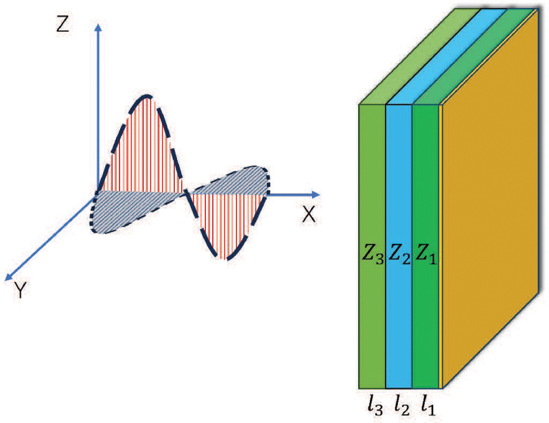
Figure 1: Schematic diagram of the absorber structure.
Water is a typical dispersive medium that conforms to the Debye model. When water is used in absorbers(), the initial step is to study its impedance characteristics. Based on the equation (9), it can be observed that the key equation governing the characteristics of water is significant. Therefore, it is singled out as for further study.
| (10) | ||
| (11) |
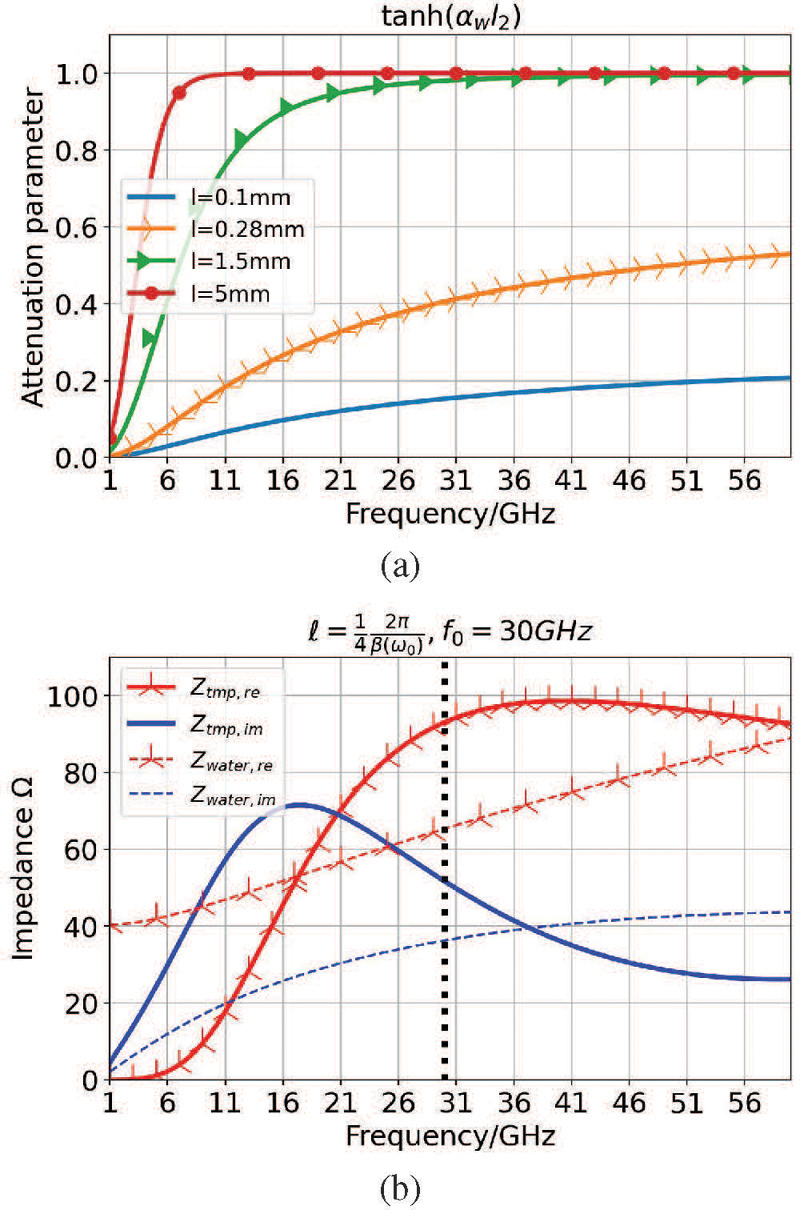
Figure 2: Curves of transmission characteristics of water layer varied as a function of frequency: (a) variations in attenuation factors and (b) changes in impedances.
The is the attenuation factor, is the propagation factor, is the thickness and is the impedance of water. It can be observed that when the water layer is sufficiently thick, the impedance of water for high-frequency EM waves remains constant, as described in equation (11) and Fig. 2 (a). This occurs because losses in water impede the propagation of high-frequency EM waves, a phenomenon known as the skineffect.
Secondly, due to the dispersive nature of water, its impedance characteristics are different from those of ordinary dielectrics. The resonance characteristics of ordinary dielectrics can be easily adjusted by varying the thickness to change the resonance points. However, it is unrealistic to arbitrarily change the thickness of water in an absorber. As illustrated in Fig. 2 (b), despite the thickness corresponding to a quarter wavelength at 30 GHz, it does not reach its maximum value at this frequency. Considering a three layers absorber structure, the impedance expression for this structure is given as follows:
| (12) | ||
where, stands for the thickness of the water layer in the middle layer. As shown in Fig. 1, a water-based absorber is a sandwich structure with a water layer placed between two layers having equal thickness of F4B materials. Extensive research has been conducted on the resonance characteristics of conventional materials, primarily controlling the resonant maxima and minima by adjusting the thickness to and .
| (13) | ||
| (14) |
It can be easily observed that the value of is significantly smaller than the real or imaginary parts of , approaching zero. Therefore, this equation can be approximated as:
| (15) |
Equation (15) illustrates that when , the impedance of the sandwich structure absorber is only related to the impedance of water. When , the impedance is determined by the impedance of F4B and water. In both cases, the impedance of the absorber at the corresponding frequency point is directly controlled by the thickness of the water layer. Therefore, subsequent research only needs to consider the thickness variation of the water layer.
In the case of absorbers with metal backplanes, achieving a perfect absorption condition with a reflection coefficient of zero is often challenging in practical applications. Therefore, in the simulations and measurement of absorbers, it is usually specified the absorption rate should exceed 10 dB, corresponding to a reflection coefficient less than 0.316.
| (16) | |
Equation (16) demonstrates that the absorption condition fundamentally entails the real and imaginary parts of impedance satisfying the equation of a circle. When and fall within the impedance circle, will meet the specified absorption requirements. Furthermore, the conditions of and can be extended to other frequencies. As long as the values of and at a specific frequency point satisfy this condition, absorption can be achieved at that frequency point. Figure 3 illustrates a schematic diagram of the absorption condition circle based on equation (16). For the sake of research convenience, the absorption circle in Fig. 3 is projected onto the and axes, and the frequency range is expanded to cover a broader spectrum.
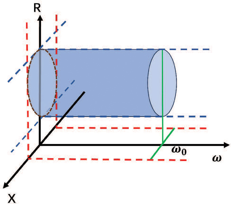
Figure 3: Schematic diagram of the absorption condition circle.
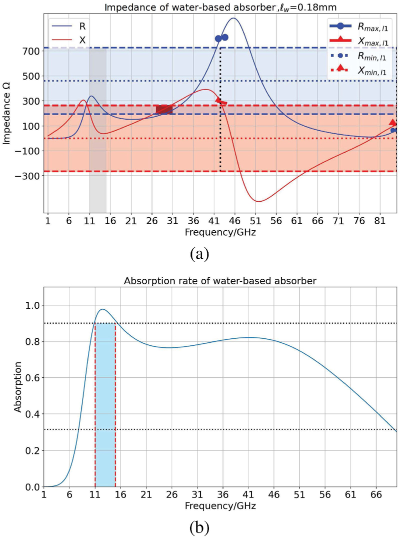
Figure 4: Absorption characteristic of a water-based absorber varied with frequency: (a) impedance values of absorber and (b) absorption rate with narrow bandwidth.
Based on the above discussion, the following steps can be taken to design an absorber with a frequency up to 42 GHz. Firstly, the value of given in equaion (15) can be rapidly determined. Furthermore, the properties of water dictate that the thickness of the water layer in the sandwich structure should not exceed 1.5 mm, effectively constraining the range of values. Subsequently, it becomes very convenient to assess absorption by calculating the impedance values at a single point and substituting it into the absorption condition circles. As shown in Fig. 4, the impedance real part exceeds the range of absorption condition at 42 GHz, so the absorber will not absorb at this frequency. It is found that the absorption condition is only met between 11 and 15 GHz, indicating that water-based absorber only exhibits absorption within this range. Note that between frequencies 27 to 31 GHz, it appears to meet the absorption conditions because the blue and red areas are used as direct projections of the circles. However, in positions near the boundaries of these two regions, the absorption conditions are not actually satisfied. Figure 4 (b) depicts the relevant absorption rate, which is quite consistent with the conclusions, with only a narrow absorption band.
Using this approach, it is easy to design an absorber that meets the absorption bandwidth of 42 GHz in a 20C environment. Additionally, it can be reasonably inferred that the impedance of the three-layer water-based absorber is continuous. Therefore, as shown in Fig. 5, by adjusting the thickness of the water layer, it is possible to make the impedance conditions around 42 GHz also satisfy the absorption criteria, thus achieving broadband absorption effectiveness. Calculations performed using HIE, FDTD, and other methods show a high degree of consistency between the absorption rate and analytical values.
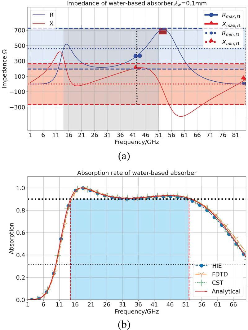
Figure 5: Wideband water-based absorber: (a) impedance values of absorber and (b) wideband absorption rate.
On a computer equipped with an AMD Ryzen 3900X CPU and 32 GB of RAM, a complete FDTD method example takes 144.2 seconds, while HIE-FDTD only consumes 77.3 seconds. This demonstrates that the introduction of the HIE method can significantly accelerate computational speed, thereby saving computational resources.
III. ELECTROTHERMAL COUPLING RESULTS AND DISCUSSION
In the discussions above, it is assumed that an ambient temperature is 20C. In reality, the process that generates absorptive effects inevitably involves energy conversion, espectically the conversion between EM energy and thermal energy. Temperature variations caused by thermal energy play a crucial role in certain materials that exhibit temperature-dependent properties.Therefore, research on the EM-thermal coupling of absorbers holds practical significance.
A. The impact of temperature on water
The properties of water are temperature-dependent and the effect of temperature on water is as follows [4]:
| (17) | ||
where, , , , , , , and , .T is temperature in C.According to equation (17), as the temperature varies, the changes in water are primarily reflected in the permittivity. Building upon this, the variations in water impedance characteristics with temperature are provided.
As observed from Fig. 6, an increase in water temperature leads to a decrease in the real and imaginary parts of water impedance within the range up to 80 GHz.

Figure 6: Impedance variation of water with temperature.
B. The impact of temperature on absorber
The fundamental approach in designing typical absorbers is to utilize resonance points where energy is directly deposited into resistive components or structures, leading to the dissipation of EM energy and the generation of heat. This process of energy conversion is equally applicable to water-based absorber.
As temperature increases, material properties also change, as discussed in Section 3.1. This alteration can affect the absorption performance, and the changes in absorption performance, in turn, influence temperature variations. This electrical-thermal coupling process is rather complex.
Based on equations (2.1) and (2.1), let us combine of the HIE-FDTD and FVM methods to provide the temperature variation and absorption performance changes of water-based absorbers under higher radiation power (10 kV).
The computation process is as follows: first, use the HIE method to obtain the electric field and polarization current distribution, then calculate the heat source. Based on this heat source, the temperature distribution can be calculated, and then the electrical properties of the absorber material can be updated using the new temperature distribution.
As seen from Fig. 7 (a), it is evident that in an ambient temperature of 20C, the water layer is the region with the fastest temperature rise during the EM wave radiation process. This is consistent with the energy conversion principle in absorbers, indicating that the EM energy in water-based absorbers is primarily dissipated within the water layer. To facilitate the observation of temperature changes with time, two points in the Fig. 7 (a) serve as temperature observation points at different positions, and an additional observation point is set in the middle of the water layer.
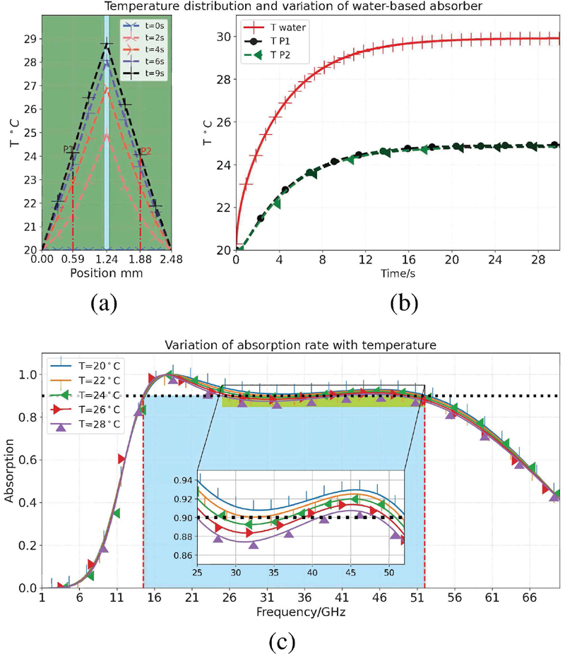
Figure 7: Absorption rate and temperature variations of broadband water-based absorber: (a) temperature distribution with position, (b) temperature variations with time, and (c) variations in absorption rate with temperature.
Figure 7 (b) illustrates that continuous radiation of EM waves causes the temperature of the water layer in the absorber structure to be higher than that of the F4B layer of the medium, and the temperature rises faster. When the water temperature rises to 29 C, the overall temperature of the absorber reaches a steady state, indicating that the structure reaches thermal equilibrium at ambient temperature environment.
Figure 7 (c) depicts the variation in absorption rate of the EM-thermal processes. It can be observed that compared to an ambient temperature of 20C, the absorption rate deteriorates with an increase of temperature. Particularly, when it approaches steady state, the absorption rate in the frequency range of 25 to 40 GHz no longer meets the requirement of greater than 0.9.
In addition, the conclusions can be obtained from the perspective of impedance from equation (15) and Figs. 5 (a) and 6. As the temperature rises, the impedance of water decreases, causing an increase in the maximum value in equation (15). Figure 5 (a) shows that the maximum value of the imaginary part is already close to the edge of the absorption condition. With further increase, it can be foreseen that the absorption condition will no longer be met.
IV. CONCLUSION
In this study, we introduced the HIE-FDTD method for EM simulations, which offers advantages in terms of computational efficiency. We also considered the impact of temperature on water and absorbers, shedding light on the EM-thermal coupling process. Through our analysis, absorber performance is affected by temperature, with higher temperatures leading to decreased absorption rates. This complex interplay between EM properties and temperature variations underscores the need for careful consideration in absorber design. Our research also demonstrated the feasibility of obtaining water-based absorbers that meet absorption criteria at specific frequencies, with practical implications for applications requiring broadband absorption. By adjusting the thickness of water layer, we can achieve effective broadband absorption. The HIE method has improved computational efficiency, making it a useful tool for future research and design efforts.
REFERENCES
[1] Y. Zhang, H. Dong, N. Mou, H. Li, X. Yao, and L. Zhang, “Tunable and transparent broadband metamaterial absorber with water-based substrate for optical window applications,” Nanoscale, vol. 13, no. 16, pp. 7831–7837, 2021.
[2] H. Xiong and F. Yang, “Ultra-broadband and tunable saline water-based absorber in microwave regime,” Optics Express, vol. 28, no. 4, pp. 5306–5316, 2020.
[3] Z. Wu, X. Chen, Z. Zhang, L. Heng, S. Wang, and Y. Zou, “Design and optimization of a flexible water-based microwave absorbing metamaterial,” Applied Physics Express, vol. 12, no. 5, p. 057003, 2019.
[4] W. Zhu, I. D. Rukhlenko, F. Xiao, C. He, J. Geng, X. Liang, M. Premaratne, and R. Jin, “Multiband coherent perfect absorption in a water-based metasurface,” Optics Express, vol. 25, no. 14, pp. 15737–15745, 2017.
[5] A. Taflove and S. C. Hagness, Computational Electrodynamics: The Finite-Difference Time-Domain Method, 3rd ed. London: Artech House, 2005.
[6] A. Z. Elsherbeni and V. Demir, The Finite-Difference Time-Domain Method for Electromagnetics with MATLAB Simulations, 2nd ed. Raleigh, NC, 2015.
[7] N. J. Ryan, B. Chambers, and D. Stone, “FDTD modeling of heatsink RF characteristics for EMC mitigation,” IEEE Transactions on Electromagnetic Compatibility, vol. 44, no. 3, pp. 458–465, 2002.
[8] M. A. Alsunaidi and A. A. Al-Jabr, “A general ADE-FDTD algorithm for the simulation of dispersive structures,” IEEE Photonics Technology Letters, vol. 21, no. 12, pp. 817–819, 2009.
[9] J. Chen and J. Wang, “A three-dimensional semi-implicit FDTD scheme for calculation of shielding effectiveness of enclosure with thin slots,” IEEE Transactions on Electromagnetic Compatibility, vol. 49, no. 2, pp. 354–360, 2007.
[10] J. Wang, B. Zhou, L. Shi, C. Gao, and B. Chen, “A novel 3-D HIE-FDTD method with one-step leapfrog scheme,” IEEE Transactions on Microwave Theory and Techniques, vol. 62, no. 6, pp. 1275–1283, 2014.
[11] K. Niu, Z. Huang, X. Ren, M. Li, B. Wu, and X. Wu, “An optimized 3-D HIE-FDTD method with reduced numerical dispersion,” IEEE Transactions on Antennas and Propagation, vol. 66, pp. 6435–6440, Nov. 2018.
[12] W. Yan, Q. Cao, and Y. Wang, “Analysis of electromagnetic/thermal coupling of debye media using HIE-FDTD method,” Journal of Electromagnetic Waves and Applications, vol. 37, no. 10-12, pp. 939–949, 2023.
[13] S. Wunsche, C. Clauß, P. Schwarz, and F. Winkler, “Electro-thermal circuit simulation using simulator coupling,” IEEE Transactions on Very Large Scale Integration (VLSI) Systems, vol. 5, no. 3, pp. 277–282, 1997.
[14] S. Watanabe, M. Karakawa, and O. Hashimoto, “Computer simulation of temperature distribution of frozen material heated in a microwave oven,” IEEE Transactions on Microwave Theory and Techniques, vol. 58, no. 5, pp. 1196–1204,2010.
[15] F. Torres and B. Jecko, “Complete FDTD analysis of microwave heating processes in frequency-dependent and temperature-dependent media,” IEEE Transactions on Microwave Theory and Techniques, vol. 45, no. 1, pp. 108–117, 1997.
[16] K.-M. Huang and Y.-H. Liao, “Transient power loss density of electromagnetic pulse in debye media,” IEEE Transactions on Microwave Theory and Techniques, vol. 63, no. 1, pp. 135–140,2014.
BIOGRAPHIES

Wen Bin Ph.D. student, the School of Electronic and Information Engineering at Nanjing University of Aeronautics and Astronautics, focuses on computational electromagnetics and the Finite-Difference Time-Domain (FDTD) method.

Yi Wang Associate professor, the School of Electronic and Information Engineering at Nanjing University of Aeronautics and Astronautics, specializes in computational electromagnetics, frequency-selective surface design, and the development of metamaterials.

Qun Sheng Professor, the School of Electronic and Information Engineering at Nanjing University of Aeronautics and Astronautics, specializes in computational electromagnetics, the Multi-Resolution Time-Domain (MRTD) method, high-speed signal integrity, electromagnetic stealth metamaterials, and the design of antenna radomes.
ACES JOURNAL, Vol. 39, No. 7, 606–613
doi: 10.13052/2024.ACES.J.390704
© 2024 River Publishers