Optimized Deep Graph Shallow Attention Neural Network Based Four-port Multiple-input-multiple-output Antenna Design for Sub-6 GHz 5G Applications
E. Suganya, T. Anita Jones Mary Pushpa, and T. Prabhu
Department of Electronics and Communication Engineering
Karunya Institute of Technology and Sciences, Coimbatore 641114, Tamil Nadu, India
suganyae@karunya.edu.in, anitajones@karunya.edu
Department of Electronics and Communication
Presidency University, Bengaluru, Karnataka 560064, India
prabhu@presidencyuniversity.in
Submitted On: March 4, 2024; Accepted On: October 17, 2024
ABSTRACT
This paper proposes a novel, four-port multiple-input-multiple-output antenna system that is considered for sub-6 GHz 5G applications. A compact multi-band circular printed monopole antenna (MCPMA) is designed for determining the appropriate dimensions of size 110.16360 mm. The device operates from 0.6 to 1 GHz. To improve cell isolation, four slits are positioned at an angle on the common ground. Deep graph shallow attention neural network with adaptive gold rush optimization algorithm (DGSANN-AGROA) is employed to create a model establishing the relationship among transmission coefficients and antenna geometric parameters. Following this, an adaptive gold rush optimization algorithm (AGROA) is utilized to enhance the antenna array’s decoupling. It showcases pattern diversity, a valuable characteristic for multiple-input-multiple-output implementation. Simulations were conducted using HFSS19 software versions, followed by an evaluation of the introduced antenna in MATLAB. The multiple-input-multiple-output antenna demonstrates favorable diversity characteristics with acceptable diversity gain (9.5 dB) and envelope correlation coefficient (ECC) (0.009).
Index Terms: Circular printed monopole antenna, deep learning, gold rush optimization, multiple-input-multiple-output, peak gain, return loss.
I. INTRODUCTION
As the number of consumers continues to rise and wireless communication technology evolves rapidly, there is a growing demand for higher throughput and channel capacity. Integrating multiple antennas into a single portable device emerges as a viable solution, promising an enhancement in communication network quality and transmission rates [1, 2, 3]. The technology central to 5G research, known as multiple-input-multiple-output (MIMO), plays a crucial role in addressing these needs [4, 5]. Several countries have already taken the lead by 5G networks.
Introducing an electromagnetic bandgap (EBG) structure between four widely spaced monopole antennas achieves a mutual coupling reduction [6, 7]. The antenna demonstrates an envelope correlation coefficient (ECC) of 0.3. Simplifying fabrication has been created but operates above 2.0 GHz [8]. In order to fulfil the needs of the sub-1 GHz and sub-6 GHz, a MIMO implementation featuring a four-port radiating antenna is introduced, utilizing coplanar waveguide (CPW) feeding [9]. The antenna features four radiating elements with multiple ports, particularly targeting the sub-6 GHz 5G NR frequencies. In this paper, a MIMO implementation featuring a four-port common radiating element antenna fed by CPW. The major contributions are as follows:
• The antenna with stub loading exhibits an omnidirectional radiation pattern, providing a pattern diversity well-psuited for implementing MIMO systems.
• The antenna’s circularly polarized feature enables it to mitigate multipath fading and provides flexibility in polarization, unlike a linearly polarized antenna.
• The outcomes of optimization using deep learning closely resemble those obtained through simulation and experimentation. Also, indicating that the suggested design is well-suited for 5G communication, due to its high diversity gain (DG), low ECC and significant isolation among radiators.
The manuscript is organized as follows. Section II presents a literature survey related to the proposed methodology. Section III provides an in-depth explanation of the proposed methodology. Section IV showcases the results and discussions. In section V, the entire paper is concluded.
II. RELATED WORKS
Wu et al. [10] introduced a MIMO antenna with an asymptote-shaped design. The design achieves polarization diversity by arranging the antenna elements orthogonally to one another. As a result, the antenna proves to be highly suitable for various applications, such as indoor positioning and tracking.
Ali and Ibrahim [11] suggested a flower-shaped MIMO antenna. The MIMO antenna was suitable for integration into portable electronic devices, enabling their operation for a wide range of applications requiring broad frequency bands.
Sarkar et al. [12] suggested an electromagnetic modelling framework for ultra-wideband (UWB) MIMO antennas. These machine learning models were implemented and evaluated to assess their performance within the modelling framework.
Elabd and Al-Gburi [13] suggested a specific absorption rate (SAR) assessment for millimeter-wave 5G smartphones. The constructed antennas showed enhancements in the overall active DG, reflection coefficient (RC) and average gain. The simulation and test results exhibited commendable alignment within the desired frequency range, suggesting the potential applicability of the design in millimeter-wave 5G smartphones.
A. Problem statement
The MIMO antenna described in existing works employs a T-shaped decoupling structure between cells, effectively achieving isolation exceeding 24 dB. In the traditional MIMO antenna design, polarization diversity and a docking floor operation contribute to an average isolation level exceeding 26 dB within the operational range. However, this antenna has drawbacks, including high ECC and excessive size. Conventional microstrip antennas commonly exhibit limitations like narrow frequency bands and variations in parameters based on the dielectric substrate. As a result, they are generally less favored in the design of antennas. In order to achieve a compact design, antennas in MIMO systems are positioned closely together. However, this proximity gives rise to the unwanted mutual coupling effect, leading to a degradation in the overall performance of the system. These motivated us to do this research work based on deep graph shallow attention neural network with adaptive gold rush optimization algorithm.
III. PROPOSED METHODOLOGY
As the consumer base expands and wireless communication technology advances rapidly, the demand for increased throughput and channel capacity has become paramount. Integrating multiple antennas into a single portable device emerges as a viable solution, ultimately enhancing both the communication network’s quality and transmission rates. Consequently, the pivotal role of MIMO technology in the forefront of 5G research becomes evident. This paper introduces the four-port MIMO antenna, termed the deep graph shallow attention neural network with adaptive gold rush optimization algorithm (DGSANN-AGROA). When it is designed with a multi-band circular printed monopole antenna (MCPMA) configuration, careful consideration of several critical parameters is imperative.
Key design elements include resonant frequency, RC, impedance bandwidth, stub position, parameters associated with the displacement of the ground plane to the right or left, and the antenna’s feed position. These design parameters significantly influence the performance characteristics of the MIMO system. Therefore, optimization of these parameters is achieved using DGSANN-AGROA to enhance predictive accuracy. The resulting optimized stub-loaded antenna features four radiating elements, providing pattern diversity conducive to MIMO implementation. Subsequently, simulations were conducted using HFSS19 software versions. The analysis encompasses performance metrics, including ECC and DG.
In the proposed design, integration of a deep graph shallow attention neural network (DGSANN) with an adaptive gold rush optimization algorithm (AGROA) is crucial for achieving balanced and robust performance across key parameters. To further enhance the antenna configuration, characteristic mode analysis (CMA) is employed. CMA, widely utilized for modal significance interpretation, is instrumental in optimizing antenna placement, bandwidth enhancement and decoupling, ultimately crafting a multiband antenna capable of operating within the 0.6-6.0 GHz range to meet higher-band communication needs.
A. Optimization to accomplish circularized polarization via the deep learning algorithm
As the number of antennas grows in higher-order MIMO design, there is a proportional increase in both required resources and costs. This phenomenon is recognized as a fundamental drawback of higher-order MIMO systems. Expanding the number of antennas in higher-order MIMO design results in an escalation of necessary resources and costs. Figure 1 illustrates the workflow of the introduced method.
Simulation results suggest that modifying the geometric values of parasitic elements (PEs) while preserving their structures has minimal impact on . As a result, the suggested DGSANN system must accurately represent the mapping relationship among the geometric variables of PEs and the antennas , excluding consideration of . Following initial DGSANN training, AGROA aids predictions. The fitness function aligns with the predicted objective. Due to incomplete DGSANN training, predictions are imprecise. These are incorporated into DGSANN training and testing data, effectively reducing the number of training samples and significantly enhancing prediction accuracy. These design parameters collectively play a crucial role in shaping the MIMO system’s performance characteristics. DGSANN is a combination of a graph neural network with a shallow attention module.
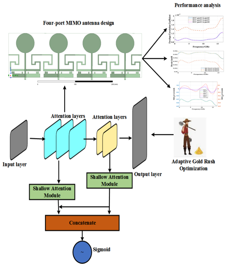
Figure 1: Procedure of introduced antenna design.
The graph attention network (GAN) presents a structure based on multi-head attention to comprehend the node’s higher-level features in a graph through the utilization of a shallow attention strategy. Each attention head possesses its own set of parameters. The majority of both training and testing datasets comprises small parameters, resulting in substantial information loss during the repeated down-sampling in convolutional neural networks (CNNs). In the realm of MIMO antenna design, addressing this issue is essential. Shallow features play a vital role due to their high resolutions, offering distinct object boundaries crucial for precise prediction.
Let us consider the impact of feedline () on modal resonance frequency () and the percentage change in resonance frequency () for four cases. By choosing appropriately (where is the radius), control over and is achieved to meet design requirements. Increasing from 0 on a fixed reduces the fundamental mode resonance frequency () for the circular printed monopole, observed consistently across all cases. By raising , decreases for a given . The figures also illustrate the effect on change, which stabilizes around 10% for larger values. Notably, operating at a specific requires a smaller feed length for a larger monopole radius and vice versa. This flexibility in choosing and provides an additional design parameter for crafting a compact monopole antenna.
Following the strategy guide, a CPW-fed antenna along with =35 mm is chosen. at (=0) is about 3 GHz, reduced to around 1.05 GHz with =65 mm (=2). Further lowering is achieved through additional metallic strip loading. Let us consider the impact of adding a metallic sheet on and multimodal resonance frequencies (=1,2,3…) controlling bandwidth. Five modal frequencies, excluding mode#4 with , are displayed. These modes satisfy over a wide frequency band. Additionally, at 0.652 GHz can be harnessed for a substantial sub-1 GHz bandwidth. , the metallic strip , becomes the ground plane modified with a slit () for the SMA connector.
These features have limitations related to the receptive field and may be overshadowed by background noise, posing challenges for direct utilization. To tackle this, let us introduce the shallow attention module (SAM) which utilizes coarse-boundary deep features to filter out background noise from .
The multi-layer’s input GAN consists of the node feature matrix and the adjacency matrix which represents the connections between nodes.
The iteration process is defined:
| (1) |
where ( denotes the identity matrix), the activation function is given as , and the learnable parameter is denoted as . The outcome is mathematically defined:
| (2) |
where and the feature maps are denoted .
The mathematical model for GSANN is given in:
| (3) | ||
| (4) |
where denotes the up-sampling operation, represents the ReLU function and indicates element-wise multiplication. Following SAM, shallow features undergo a significant enhancement, becoming clearer and offering crucial cues for small parameters. SAM also plays a vital role in achieving feature balance across various blocks. The computation of output features for nodes is expressed in:
| (5) |
where is the output feature, concatenates the outcomes from various attention strategies, represents the count of attention heads and is a weight matrix. The attention coefficient , which signifies the relationship among every input node and its first-order neighbor, is computed by:
| (6) |
where represents the exponential function, and denote matrix of nodes and , is the sum over all nodes that are neighbors of node , represents a learnable weight vector, is its appropriate transpose, and is a activation function where equals 0 when is negative. Subsequently, the function is used to normalize all neighbor nodes of , which is mentioned in:
| (7) |
where represents the probability of , and denotes the weight matrix and denotes the bias vector. The variables correspond to the embedding features learned by preceding layers.
The GAN-based system employs three consecutive GAN layers, each initiated by the ReLU operation. Traditionally, GANs are utilized for node classification, where the outcomes are node-level feature vectors. To derive graph-level features, employ max pooling method collective features from all nodes within the graph and assess their performance.
Evaluation reveals that incorporating a max pooling layer within the GAN-based architecture yields superior results compared to other pooling methods. Consequently, we integrate a global max pooling layer after the final GAN layer to effectively extract and represent the overall features.
By employing combinations with labels, the model was trained using cross-entropy as the loss function. The goal is to minimize the loss throughout the training process:
| (8) |
where is the loss, denotes the set encompassing all bias and trainable weight parameters within the system. represents the total number of samples, signifies the th sample’s label, and represents an L2 regularization hyper-parameter. In this work, the optimal parameters are extracted with the help of AGROA approach.
B. AGROA for enhancing the antenna array’s decoupling
A significant historical occurrence related to gold is the gold rush, signifying a remarkable influx of individuals aspiring to amass wealth [14].
Table 1 provides the pseudocode for the GRO method. The mathematical model for the fitness function is:
| (9) |
where denotes the resonant frequency, represents RC, and is the stub position. Cost function minimization in antenna design is crucial for optimizing key performance parameters such as , , and . The resonant frequency is targeted to ensure the antenna operates effectively at the intended frequency, while the reflection coefficient is minimized to achieve better impedance matching and reduce power loss. Stub positions are optimized for fine-tuning impedance and other performance metrics. The cost function combines these parameters into a single metric that the optimization algorithm minimizes, balancing trade-offs and guiding adjustments to find the best configuration. By minimizing deviations from desired values for , and , the cost function ensures no parameter becomes a significant weak point, leading to a well-rounded, robust and reliable antenna design. This approach systematically enhances antenna performance across all critical aspects for promoting robust and reliable performance.
Table 2: Design parameters of introduced antenna
| Parameters | ||||||||||
| Value | 110.16 | 80 | 24.6564 | 52 | 3.24 | 38 | 9 | 1.62 | 7 | 0.5 |
| Parameters | ||||||||||
| Value | 5.2136 2.97 |
5.0976 3.3156 |
4.6764 1.9548 |
39 4.2444 |
16.9992 2.29608 |
13.0032 2.29608 |
6.00372 2.6352 |
9.35282.1168 | 23.8032 2.1168 |
28 2 |
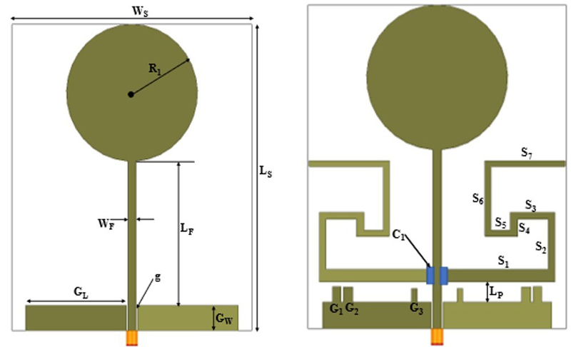
Figure 2: Antenna (a) structure and (b) circular printed monopole.
In this paper, DGSANN-AGROA is used to design a novel four-port MIMO antenna system that is considered for sub-6 GHz 5G applications. Following this, an AGROA is utilized to enhance the antenna array’s decoupling.
IV. RESULTS AND DISCUSSIONS
Simulations are performed using HFSS19 software, followed by an assessment of the introduced antenna in MATLAB. The performance measures which are utilized to show the effectiveness of the introduced antenna design are gain, ECC and DG.
Table 2 provides the introduced antenna design parameters.
The antenna component, the surface current density () at the frequency 0.643 GHz, and the RC of the antenna are illustrated in Figs. 2 (a, b). Figure 2 (b) presents a depiction of the antenna modified with stub loading. To improve the bandwidth, the antenna’s impedance matching range is improved by introducing stubs , and , as illustrated in Fig. 2 (b). These stubs improve the impedance matching range, allowing the antenna to achieve better performance over a wider frequency range.
As an outcome of these modifications, the antenna exhibits resonance at an exceptionally minimum frequency of 0.605 GHz, accompanied by a 34% fractional bandwidth. This means the antenna can operate effectively over a broader range of frequencies, making it more adaptable to different applications. The use of stub loading is key to this performance enhancement, as it allows for precise tuning of the resonant frequency and a significant increase in operational bandwidth.
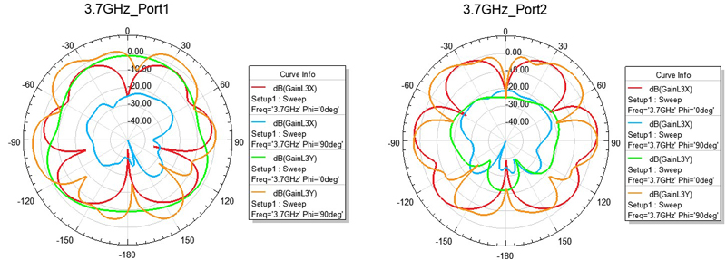
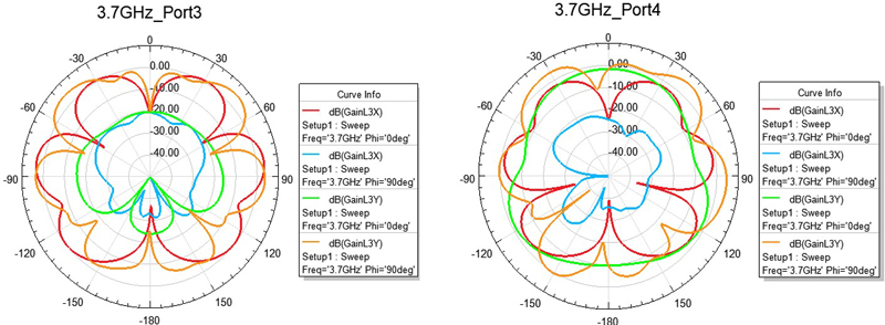
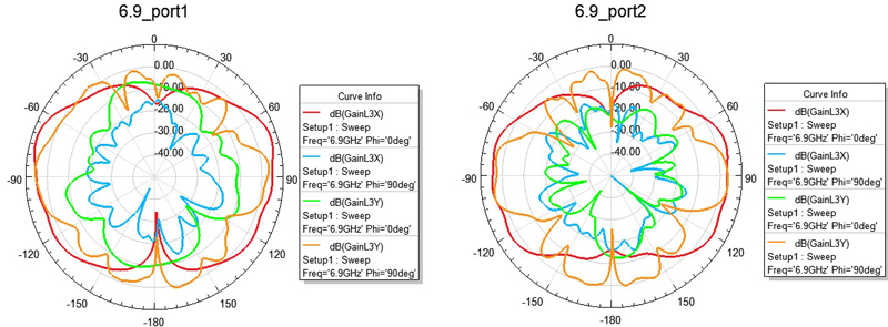
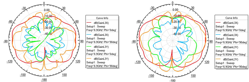
Figure 3: Computed 2D radiation pattern: (a) port 1, (b) port 2, (c) port 3, (d) port 4 at 3.7 GHz, (e) port 1, (f) port 2, (g) port 3, and (h) port 4 at 6.9 GHz.
Due to frequency limitations, the antenna’s 2D radiation patterns at 3.7 and 6.9 GHz were exclusively measured at all four ports using the standard horn. The results exhibit reasonable coverage yet, at 6.9 GHz, elevated cross-polarization occurs due to the anechoic chamber’s limited noise floor. Despite some deviation caused by substrate sagging and mechanical support issues, the measurements offer valuable insights regarding the overall radiation characteristics of the antenna. Figure 3 illustrates the 2D radiation pattern of the introducedantenna.
The axial ratio of the introduced circularly polarized antenna was measured at 3.7 GHz and 6.9 GHz using a standard antenna. At 3.7 GHz, the antenna exhibited reasonable coverage, with the axial ratio likely below 3 dB, indicating good circular polarization performance. However, at 6.9 GHz, the measurements showed elevated cross-polarization due to the limited noise floor. This suggests a higher axial ratio at this frequency, which impacts the ideality of circular polarization. Causing interference, nulls, zones of weak or no signal, could also be identified, impacting desired coverage areas. Analyzing beamwidth, the angle of strong signal, is crucial. A narrow beam might be ideal for satellite communication but unsuitable for a cell tower needing broad coverage. Asymmetry in the pattern, potentially caused by imperfections or nearby objects, can lead to uneven signal strength. Figure 3 (a) illustrates the lobes for port 1 may have a specific orientation, indicating stronger radiation in particular directions. Figure 3 (b) demonstrates the shape of the lobes might differ, with port 2 having wider or narrower lobes compared to port 1. In Fig. 3 (c), the pattern of port 3 appears more consistent across different phi angles, whereas port 4 shows more variation. Figure 3 (d) port 4 shows more complexity in the side lobe structure, indicating potential differences in antenna design. The port radiation pattern in Fig. 3 (e) should exhibit a symmetricaldistribution.
Figure 3 (f) is similar to port 1. This port should also show a symmetrical radiation pattern, ensuring good coverage without significant nulls or weak zones.
The pattern in Fig. 3 (g) should be checked for uniformity and any deviations that might indicate interference or reflection issues. The radiation pattern symmetry and coverage in Fig. 3 (h) are crucial for ensuring consistent signal strength and minimal interference.
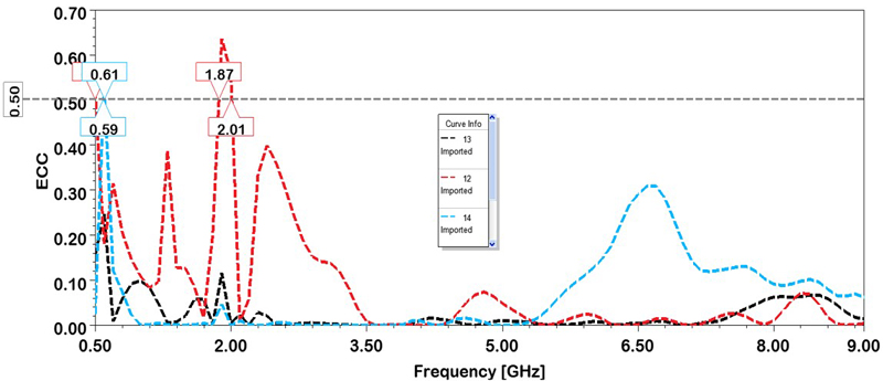
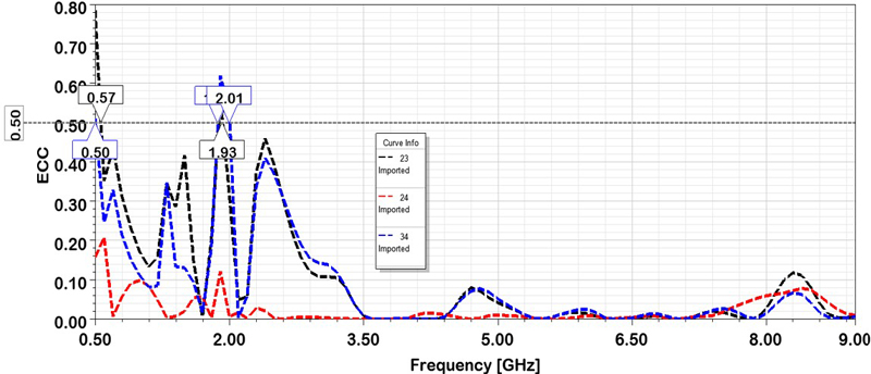
Figure 4: Envelope correlation coefficient among (a) port 1 and others and (b) ports 2, 3, and 4.
In Fig. 4 (a), ECC curves show correlation levels between port 1 and other ports. Figure 4 (b) displays ECC curves among the remaining ports (2, 3, 4) meeting the MIMO system requirements for antenna correlation parameters. The ECC values are critical for determining the performance of MIMO systems, as it measures the correlation between signals received or transmitted by different antenna elements. All ports are excited at a frequency of 3.5 GHz. ECC values should ideally be below 0.5. In this graph, due to the antennas being placed adjacent to each other, antenna pairs 1 and 2 show higher correlation compared to pair 1 and 3, and pair 1 and 4. However, at desired frequencies like 1 GHz, 3.7 GHz and 6.9 GHz, the ECC values remain below 0.31. These low ECC values signify minimal correlation, validating the antenna’s suitability for MIMOapplications.
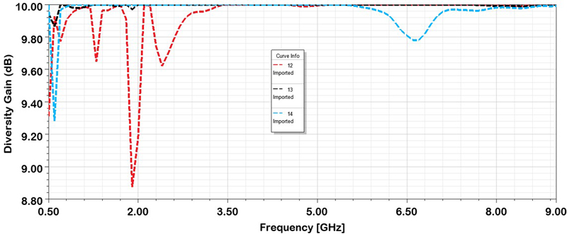
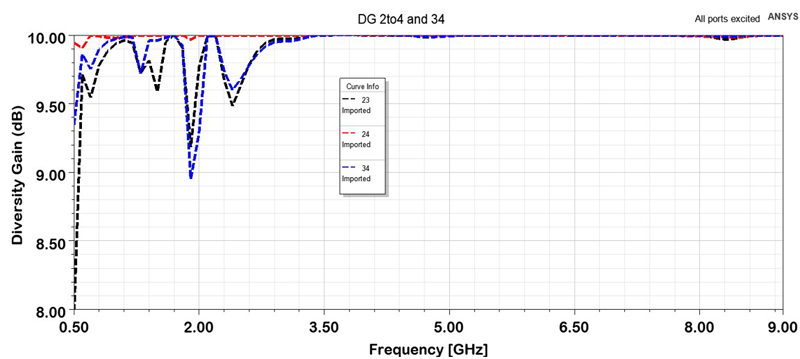
Figure 5: Diversity gain among (a) port 1 and (b) port 2.
If all the ports are excited, ECC values should be below 0.5. This minimal correlation is essential for ensuring efficient MIMO performance, as it allows for better signal diversity and improved data throughput. Thus, antenna design effectively meets the requirements for MIMO systems, demonstrating its suitability for applications that demand high-performancemulti-antenna configurations. In Fig. 4 (b), due to the antennas being placed adjacent to each other, pair 2 and 3, and pair 3 and 4, exhibit higher correlation compared to pair 2 and 4.
DG is a vital parameter characterizing the diversity features of the model. It quantifies improvement in signal quality due to the use of multiple antennas to receive or transmit the signal. High DG values indicate effective mitigation of fading and signal degradation, which are common in wireless communication environments. As indicated in Fig. 5, the DG at ports 1 and 2 for the proposed antenna surpasses 100 dB. This is a remarkably high value, indicating that the antenna system has excellent diversity performance. Such a high DG suggests that the antennas are capable of effectively combining signals from different paths, reducing the impact of signal fading and improving overall signal reliability and quality. This observation suggests that MIMO antennas exhibit strong diversity properties, emphasizing their capability to enhance performance in diverse signal conditions. Table 3 provides a comparison of ECC metrics between the proposed method and existingmethods.
Table 3: Four-port antenna design comparison
| Four-port Antenna Design | ECC/dB |
| Koch fractal element (four-port antenna) [16] | 0.4 |
| Four-port MIMO antenna [17] | 0.0408 |
| Four-port millimeter wave MIMO antenna [18] | 0.50 |
| DGSANN-AGROA (proposed) | 0.009 |
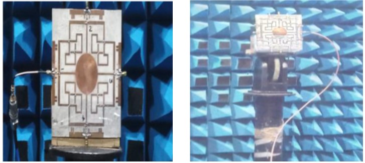
Figure 6: Antenna: (a) fabricated prototype and (b) under testing in the anechoic chamber.
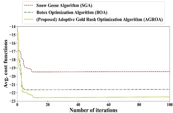
Figure 7: Comparison of cost complexity.
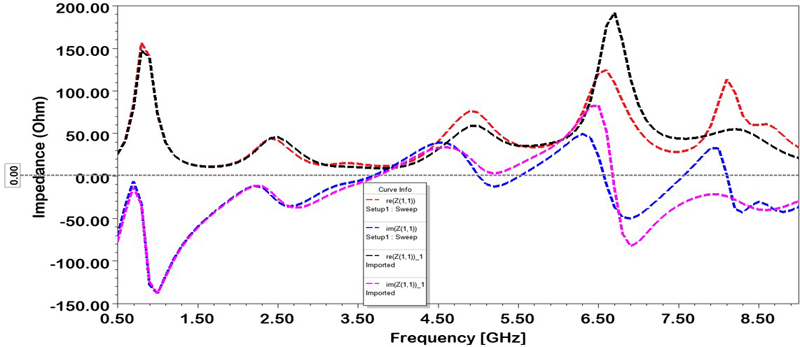
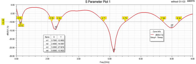
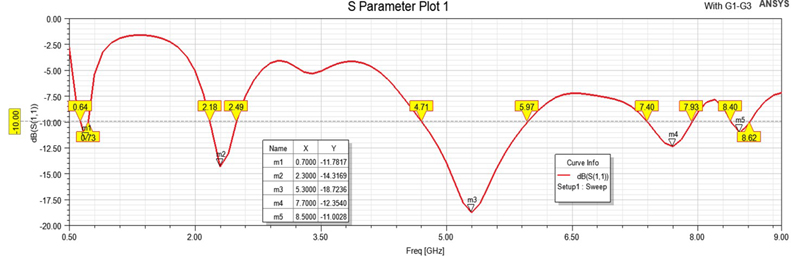
Figure 8: Ground stubs effect: (a) impedance (b) RC (without ) and (c) RC (with ).
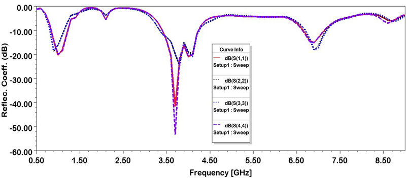
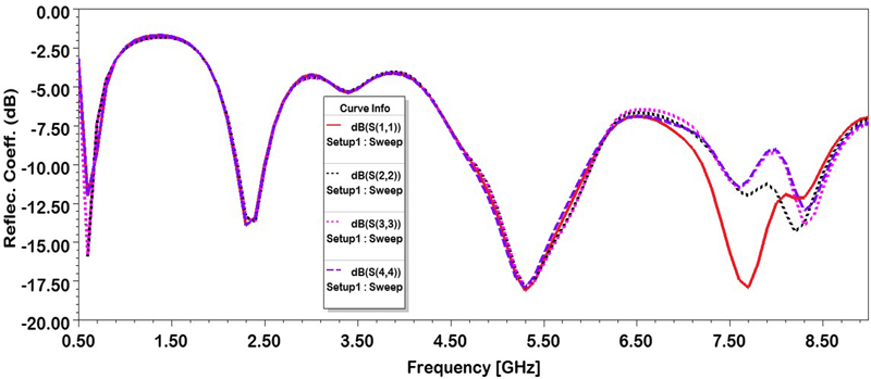
Figure 9: MIMO antenna S-parameters: (a) RC with strips and (b) RC without strips.
The antenna was fabricated using an EP42 auto prototyping machine from Everprecision PCB. It was subsequently tested in the anechoic chamber at the Antenna and Microwave Design laboratory. The resulting planar four-port antenna is illustrated in Fig. 6.
Figure 7 illustrates the cost complexity comparison of the proposed method with existing methods. This line graph depicts the performance of three algorithms: Snow Geese Algorithm (SGA) [19], Botox Optimization Algorithm (BOA) [20] and Adaptive Gold Rush Optimization Algorithm (AGROA). The graph tracks the average cost function as the number of iterations increases. AGROA appears superior as its cost function decreases more significantly: 20-22 seconds is needed to train thenetwork.
Figure 8 (a) demonstrates the impact of stub loading on the () real and () imaginary parts of impedance. The addition of to the small ground plane (8.4mm) increases inductance, improving and enhancing impedance matching. This modification also alters . Figures 8 (b,c) compare the magnitude of RC with and without , illustrating that the increased leads to an improved 6 dB impedance matching level above 3.9 GHz across a wide range.
From the observations in Fig. 9, it is evident that slight shifts occur in the RC at various end ports for the antenna at varying frequencies. However, good matching is achieved in other regions. Note, and maintain an isolation below -11.77 dB, maintain an isolation below -21.66 dB and maintains an isolation below-29.33 dB.
V. CONCLUSION
This paper presents the design of a compact four-port MIMO antenna with strong isolation capabilities. The proposed MIMO antennas achieve an isolation of -29.33 dB without compromising the overall antenna size. Simulated results show that the newly introduced antenna maintains a consistent omnidirectional radiation pattern, demonstrating outstanding gain, efficiency and high isolation as a four-port system. Furthermore, the MIMO antenna demonstrates favorable diversity characteristics with acceptable DG (9.5 dB) and ECC (0.009), establishing its excellence as a MIMO antenna with exceptional performance. A four-port antenna setup with a co-surfaced ground plane holds promise as a design for creating conformal and three-dimensional MIMO antennas in thefuture.
REFERENCES
[1] B. Baz, D. Jansari, S. P. Lavadiya, and S. K. Patel, “Miniaturized and high gain circularly slotted 44 MIMO antenna with diversity performance analysis for 5G/Wi-Fi/WLAN wireless communication applications,” Results in Engineering, vol. 20, p. 101505, 2023.
[2] M. Munir, S. H Kiani, H. Savci, D. A. Sehrai, F. Muhammad, A. Ali, H. Mostafa, and N. O. Parchin, “mmWave polarization diversity wideband multiple-input/multiple-output antenna system with symmetrical geometry for future compact devices,” Symmetry, vol. 15, no. 9, p. 1641,2023.
[3] P. Tiwari, V. Gahlaut, M. Kaushik, A. Shastri, V. Arya, I. Elfergani, C. Zebiri, and J. Rodriguez, “Enhancing performance of millimeter wave MIMO antenna with a decoupling and common defected ground approach,” Technologies, vol. 11, no. 5, p. 142, 2023.
[4] D. Burghal, Y. Li, P. Madadi, Y. Hu, J. Jeon, J. Cho, A. F. Molisch, and J. Zhang, “Enhanced AI based CSI prediction solutions for massive MIMO in 5G and 6G systems,” IEEE Access, vol. 11, pp. 117910-117825, 2023.
[5] S. S. Tyokighir, J. Mom, K. E. Ukhurebor, and G. Igwue, “New developments and trends in 5G technologies: Applications and concepts,” Bulletin of Electrical Engineering and Informatics, vol. 13, no. 1, pp. 254-263, 2024.
[6] A. D. Tadesse, O. P. Acharya, and S. Sahu, “Wideband MIMO antenna mutual coupling reduction with electromagnetic band-gap structure,” IETE Journal of Research, vol. 69, no. 9, pp. 6014-6021, 2023.
[7] A. Ali, M. Munir, M. M. Nasralla, M. Esmail, A. J. A. Al-Gburi, and F. A. Bhatti, “Design process of a compact tri-band MIMO antenna with wideband characteristics for sub-6 GHz, Ku-band, and millimeter-wave applications,” Ain Shams Engineering Journal, vol. 15, no. 3, p. 102579,2024.
[8] F. Taher, H. A. Hamadi, M. S. Alzaidi, H. Alhumyani, D. Elkamchouchi, Y. Elkamshoushy, M. T. Haweel, M. F. A. Sree, and S. Y. A. Fatah, “Design and analysis of circular polarized two-port MIMO antennas with various antenna element orientations,” Micromachines, vol. 14, no. 2, p. 380, 2023.
[9] S. Ghosh, G. S. Baghel, and M. V. Swati, “Design of a highly-isolated, high-gain, compact 4-port MIMO antenna loaded with CSRR and DGS for millimeter wave 5G communications,” AEU-International Journal of Electronics and Communications, vol. 169, p. 154721, 2023.
[10] A. Wu, Y. Tao, P. Zhang, Z. Zhang, and Z. Fang, “A compact high-isolation four-element MIMO antenna with asymptote-shaped structure,” Sensors, vol. 23, no. 5, p. 2484, 2023.
[11] W. A. Ali and R. A. Ibrahim, “Highly compact 44 flower-shaped MIMO antenna for wideband communications,” Applied Sciences, vol. 13, no. 6, p. 3532, 2023.
[12] D. Sarkar, T. Khan, Jayadeva, and A. A. Kishk, “Machine learning assisted hybrid electromagnetic modeling framework and its applications to UWB MIMO antennas,” IEEE Access, vol. 11, pp. 19645-19656, 2023.
[13] R. H. Elabd and A. J. Al-Gburi, “SAR assessment of miniaturized wideband MIMO antenna structure for millimeter wave 5G smartphones,” Microelectronic Engineering, vol. 282, p. 112098, 2023.
[14] K. Zolf, “Gold rush optimizer: A new population-based metaheuristic algorithm,” Operations Research and Decisions, vol. 33, no. 1, pp. 113-150, 2023.
[15] S. Modak and T. Khan, “A slotted UWB-MIMO antenna with quadruple band-notch characteristics using mushroom EBG structure,” AEU-International Journal of Electronics and Communications, vol. 134, p. 153673, 2021.
[16] A. Kumar, V. Prakash, and S. C. Padhy, “Four port MIMO antenna for IoT applications in public safety band and sub-6 GHz TDD 5G band,” Engineering Research Express, vol. 6, no. 1, 2024.
[17] M. Srinubabu and N. V. Rajasekhar, “Enhancing diversity and isolation performance for afour-port MIMO antenna in FR-1 5G frequency bands,” IETE Journal of Research, vol. 70, no. 8, pp. 1-16, 2024.
[18] M. Sharma, A. Kumar, V. Kikan, G. Jaitly, S. Bhardwaj, and T. Bano, “Conformal ultra-compact narrowband 60.0 GHz four-port millimeter wave MIMO antenna for wearable short-range 5G application,” Wireless Networks, vol. 30, no. 3, pp. 1-17, 2024.
[19] A. Q. Tian, F. F. Liu, and H. X. Lv, “Snow Geese Algorithm: A novel migration-inspired meta-heuristic algorithm for constrained engineering optimization problems,” Applied Mathematical Modelling, vol. 126, no. 8, pp. 327-347,2024.
[20] M. Hubálovská, Š. Hubálovský, and P. Trojovský, “Botox Optimization Algorithm: A new human-based metaheuristic algorithm for solving optimization problems,” Biomimetics, vol. 9, no. 3, p. 137, 2024.
BIOGRAPHIES

E. Suganya received her B.E. in electronics and communication engineering from the Bannari Amman Institute of Technology, Tamil Nadu, India, in 2009 and M.E. in communication systems from the Kumaraguru College of Technology, Tamil Nadu, India, in 2012. She is currently pursuing her Ph.D. in electronics and communication engineering at Karunya Institute of Technology and Sciences, India. She is an Assistant Professor in the Department of Electronics and Communication Engineering at Nitte Meenakshi Institute of Technology (NMIT), Bengaluru, India. She is a member of IEEE, ISTE and IAENG. Her area of interest includes planar antenna design, MIMO communication and wireless communication.

T. Anita Jones Mary Pushpa received her B.E. in electronics and communication engineering from Madurai Kamaraj University, Tamil Nadu, India, in 1998 and M.E. in communication systems from Madurai Kamaraj University, Tamil Nadu, India, in 1999. She completed her Ph.D. in information and communication engineering from Anna University, India, in 2014. She is an Associate Professor in the Department of Electronics and Communication Engineering at Karunya Institute of Technology and Sciences, India. She is a life member of IETE. Her area of interest includes miniaturized antennas and microwave communication.

T. Prabhu received the B.E. degree in electronics and communication engineering from Anna University, Chennai, India, in 2009 and M.E. degree in communication systems from Anna University, Chennai, India, in 2011. He completed his Ph.D. degree in information and communication engineering from Anna University, India, in 2021. He started his career at Cognizant Technology Solutions for two years and then joined in SNS College of Technology and worked for nine years. During this period, he has organized Faculty Development Programme, Workshop, Seminar, Webinars and Training Programme. He has published papers in SCI, Scopusand UGCjournals. He also presented many technical papers in national and international conferences. He is an active member in IEEE, theIRED, IAENG and ISRD. His area of interest includes antenna design and MIMO communication. Currently, he is working as an Assistant Professor in Department of Electronics and Communication Engineering at Presidency University, Bengaluru, India.
ACES JOURNAL, Vol. 39, No. 9, 773–785
doi: 10.13052/2024.ACES.J.390903
© 2024 River Publishers