Parallel Structured Mesh Generation for FDTD Simulations by MPI Implementation
Jiale Guo and Juan Chen
Department of Information and Communication Engineering Xi’an Jiaotong University, Xi’an, Shaanxi, China
gjl_0610@163.com, chen.juan.0201@mail.xjtu.edu.cn
Submitted On: March 11, 2024; Accepted On: October 25, 2025
ABSTRACT
A parallel structured mesh generation method is proposed for FDTD (Finite Difference Time Domain) simulation in this paper by MPI (Message Passing Interface) implementation. This parallel method is based on serial projection and ray tracing. It completely implements the process from surface triangles recorded in a STL (STereoLithography) file to solid hexahedral grids. Furthermore, the parallel method realizes the balanced task allocation for processes which provides almost linear parallelism. Experimental results show that the running time of the MPI program increases in a nearly linear way. As the number of processes increases, the efficiency of the parallel program consistently remains above 80%.
Keywords: FDTD, MPI, parallel projection, ray tracing, STL file, structured mesh generation.
1 INTRODUCTION
The finite difference time domain (FDTD) method is one of the most common methods in the field of computational electromagnetics since Yee proposed it [1]. It solves Maxwell equations by space and time discretization. The computation space needs to be divided into hexahedral units which are called Yee cells. The Yee cell size determines the accuracy and efficiency of FDTD. Therefore, mesh generation is essential for FDTD simulation.
Since the Yee cell concept was first proposed for FDTD simulation in 1966, numerous FDTD mesh generation methods have been proposed, such as projection [2], volume rendering [5], ray tracing [9], and tetrahedral conversion [16]. These methods realize accurate identification of Yee cells for all kinds of models. However, when the target model is complex or large-scale, the computation time rises. A parallel method is needed to shorten computation time.
To fully improve efficiency of mesh generation in such cases, this paper proposes a parallel structured mesh generation method by MPI (Message Passing Interface) technique for FDTD simulation. The parallel method is based on serial projection-ray tracing. For models which are complex or large, different parallel schemes are designed. The parallel projection method realizes the best allocation for all primitives. The parallel ray tracing method realizes the most average allocation for all grids. Furthermore, parallel IO technology is used to realize data transmission among different modules. To verify the efficiency of the parallel method, a large-scale submarine is simulated with billion-scale grids. According to the simulation result, the parallelism of our method maintains at over 80% which can significantly shorten runtime.
2 PARALLEL METHOD
Before FDTD simulation, spatial discretization is needed. To realize the mapping from surface triangles recorded in the STL (STereoLithography) file to hexahedral Yee cells, we propose the serial projection-ray tracing method from our previous work [20, 21]. As shown in Fig. 1, the serial method requires three steps: generate adaptive mesh lines, identify the surface Yee cells (surface fitting), then fill in the internal Yee cells (internal filling). After finishing the three steps, the surface triangles of the object are converted to structured grids for FDTD simulation.
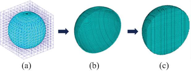
Figure 1 Process from surface triangles to hexahedral Yee cells: (a) generate adaptive mesh lines, (b) surface fitting, (c) internal filling.
Though the projection-ray tracing method proposed realizes fast grid generation for FDTD method, it still consumes much time when it comes to complex models with enormous primitive elements and the billions of Yee cells required by large-scale models. A parallel method is needed to accelerate the algorithm for such cases. In terms of the serial method, the adaptive mesh line generation is difficult to parallelize for its frequent global operations while the remainder of the method is parallelizable. Thus, the parallel method includes the paralleled projection method and the paralleled ray-tracing method mainly. The paralleled projection method aims at allocating primitive elements evenly to different processes. The paralleled ray-tracing method aims at allocating Yee cells evenly to different processes. Parallel IO (input and output) is used for data transmission among processors. The specific parallel method follows.
2.1 Parallel projection method
In the proposed projection method, we convert the triangle elements to the corresponding surface structured grids. The mapping between the two is non-linear which is hard to parallelize directly. This paper proposes a parallel projection method which can achieve linear parallelism nearly based on the projected area. According to the proposed projection method, the actual computational load is relevant to the number of grids in the projection area. Our parallel strategy is to allocate triangles to processors so that they have similar grid amounts. As shown in Fig. 2, the triangle (assume its number is ) is projected onto three coordinate planes, forming the projected area , , . Assume the grid number of the projected area is in the -direction, in the -direction, in the -direction, the corresponding grid areas , , are , , . Then, for triangle , the total grid is calculated as:
| (1) |
where , , are:
| (2) |
The total number of grids of all triangles is:
| (3) |
Assuming there are processes for accelerating totally, to obtain linear parallelism, the ideal grids amount allocated to each process is:
| (4) |
However, the actual grids amount of each process cannot be completely equal to under the condition that one triangle cannot be split by different processes but can only be allocated to a single process. Thus, the ideal allocation for the triangles is to make minimum. The calculation method of is:
| (5) |
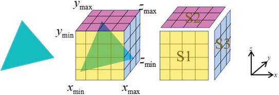
Figure 2 Parallel projection method based on projected area.
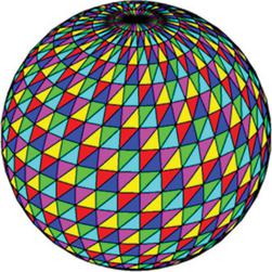
Figure 3 Balanced allocation for triangles on the sphere.
By optimized resource scheduling according to equation (6), the distribution of is close to . As shown in Fig. 3, the triangles are allocated to different processes (each color represents a process). Each process has similar computation under the most balanced allocation based on (6). In this way, the acceleration ratio achieves almost linear growth.
2.2 Parallel ray tracing method
The ray tracing method is completely parallelizable for the independence of paralleled rays. According to the algorithm, the whole area can be divided to subareas along the direction of the rays. The subareas are also completely independent which doesn’t require process communication. As shown in Fig. 4, assume the ray is along the -direction, the whole area is divided to four subareas which are split evenly in the -direction and the -direction according to the amount of processes. Each process executes the ray tracing method independently for its corresponding subarea and the ultimate results can be gathered by all processes. Because those subareas cover similar numbers of grids, the parallelism of the ray tracing method is perfectly linear.
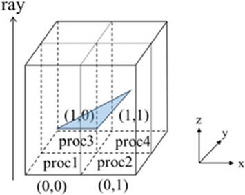
Figure 4 Parallel ray tracing method.
2.3 Parallel IO
Because the projection method and ray tracing method take a different parallel strategy, the global data needs be transmitted among different processes. The ultimate result needs to be gathered and output as Yee cells’ data for electromagnetic calculation. As shown in Fig. 5, parallel IO is used to realize data transmission through a common file interface, which also supports nearly linear parallelism when there aren’t too many processes. On the stage of surface fitting, processes are allocated with different triangles. As soon as all processes finish surface fitting, the local data of each process is written parallelly to the common file. Then all processes read the whole common file to get global data. Following that, global data are reallocated to different processes according to the regional location to carry out internal filling. Finally, complete data are output parallelly to a result file.
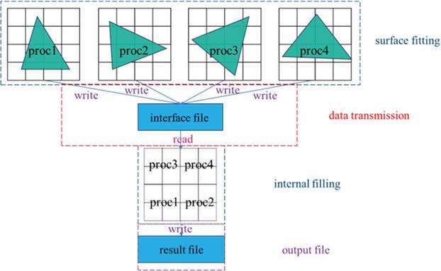
Figure 5 Parallel projection-ray tracing method scheme.
Based on the parallel method projection module, the ray tracing module and the IO module are completely linearly parallel except for the adaptive mesh line generation module. However, the computation time of the module is relatively small. Therefore, the whole process achieves nearly linear parallelism ignoring the computation time of adaptive mesh line generation.
3 SIMULATION RESULTS
To demonstrate the parallelism of the proposed parallel projection-ray tracing method, a large-scale model (submarine) is considered which has more geometric primitives and generates more Yee cells.
The submarine model and material mapping result are shown in Fig. 6. The length of the submarine is 62 m. The width is 11 m and the height is 20 m. It includes 10695 triangle elements. The simulation time of the sequential program reaches hundreds of seconds which greatly speeds up using the parallel method.
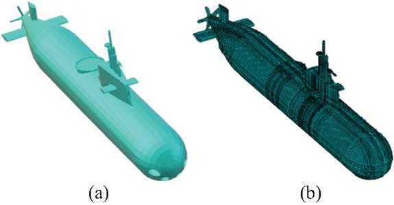
Figure 6 Simulation of submarine: (a) original model and (b) structured mesh generated.
We choose 200, 400, and 1700 million grids for multi-point parallelism testing. The time of three modules, total time, acceleration ratio, and efficiency are shown in Tables 1–3. The three modules include the mesh line generation module, the surface fitting module, the internal filling module, and the parallel IO module. Total time is slightly more than the sum of the four main modules, allowing extra time for MPI function expenses and synchronous operations. Speedup and Efficiency are calculated as follows.
Table 1 Simulation time comparison on 200 million grids of 1, 2, 4, 8, 16 processes for submarine
| Process | Mesh Line | Surface | Internal | Parallel | Total | Total | Total |
| Amount | Generation | Fitting | Filling | IO | Time | Speedup | Efficiency |
| 1 | 0.43 s | 38.03 s | 23.22 s | 36.87 s | 99.93 s | – | – |
| 2 | 0.43 s | 21.75 s | 11.44 s | 18.26 s | 52.13 s | 1.91 | 0.96 |
| 4 | 0.43 s | 11.86 s | 5.69 s | 9.47 s | 27.85 s | 3.59 | 0.90 |
| 8 | 0.44 s | 7.37 s | 2.78 s | 4.86 s | 15.91 s | 6.29 | 0.80 |
| 16 | 0.44 s | 4.86 s | 1.41 s | 2.73 s | 9.77 s | 10.23 | 0.64 |
Table 2 Simulation time comparison on 400 million grids of 1, 2, 4, 8, 16 processes for submarine
| Process | Mesh Line | Surface | Internal | Parallel | Total | Total | Total |
| Amount | Generation | Fitting | Filling | IO | Time | Speedup | Efficiency |
| 1 | 0.48 s | 59.93 s | 49.62 s | 84.82 s | 197.27 s | – | – |
| 2 | 0.48 s | 35.01 s | 24.54 s | 42.89 s | 107.03 s | 1.84 | 0.92 |
| 4 | 0.48 s | 19.19 s | 8.49 s | 21.53 s | 53.83 s | 3.66 | 0.92 |
| 8 | 0.50 s | 11.97 s | 5.83 s | 10.96 s | 31.37 s | 6.29 | 0.80 |
| 16 | 0.51 s | 6.95 s | 3.05 s | 6.32 s | 17.14 s | 11.51 | 0.72 |
Table 3 Simulation time comparison on 1700 million grids of 1, 2, 4, 8, 16 processes for submarine
| Process | Mesh Line | Surface | Internal | Parallel | Total | Total | Total |
| Amount | Generation | Fitting | Filling | IO | Time | Speedup | Efficiency |
| 1 | 0.61 s | 151.65 s | 186.56 s | 320.01 s | 674.22 s | – | – |
| 2 | 0.61 s | 80.07 s | 89.47 s | 155.37 s | 331.67 s | 2.00 | 1.00 |
| 4 | 0.61 s | 42.56 s | 43.67 s | 80.27 s | 173.50 s | 3.89 | 0.97 |
| 8 | 0.62 s | 28.60 s | 21.46 s | 40.68 s | 93.39 s | 7.22 | 0.90 |
| 16 | 0.62 s | 16.20 s | 10.76 s | 23.72 s | 53.03 s | 12.71 | 0.80 |
Assume there are processes for accelerating, represents total time of processes, represents speedup of processes, represents efficiency of processes, represents total time of one process, which is equal to sequential time. Then, and are calculated as:
| (6) | |
| (7) |
According to the simulation time results shown in Tables 1–3, the time of the Mesh Line Generation module is a tiny number which barely influences the total time of the program, the rest of the modules (Surface Fitting, Internal Filling, Parallel IO) consume half of the time with the number of processes growing exponentially. The Efficiency of the parallel program maintains at over 80% for 1–8 processes and the Speedup rises nearly linearly. With the number of processes increasing, MPI function expenses and synchronous operations between processes cause the decline of Speedup and Efficiency. Except for the Mesh Line Generation module, the rest of the modules show good linear parallelism. This method has better speedup and efficiency when the amount of grids increase. In general, the program shows a nearly linear parallelism, neglecting delay effects.
4 CONCLUSION
This paper presents a parallel structured mesh generation method for FDTD simulation. The method takes the STL file as input file, uses the projection method for surface fitting, and the ray tracing method for internal filling. As the result, the surface triangle elements recorded in the STL file are converted to Yee cells for electromagnetic calculation using the FDTD method. To reduce excessive computation time caused by enormous geometric primitives and billion-scale grids, the parallel projection method and parallel ray tracing method are proposed. To verify the parallelism of the method, a submarine is simulated with 200, 400, and 1700 million grids. The simulated result shows that the method has nearly linear parallelism for both simulations. It shows the proposed parallel method is helpful to deal with large-scale problems for the FDTD method.
ACKNOWLEDGMENT
This work was supported in part by the Key Research and Development Program of China (No. 2020YFA0709800), in part by the National Natural Science Foundation of China (62122061), and in part by the Shaanxi Natural Science Basic Research Project of Shaanxi Science and Technology Office (No. 2023-JC-QN-0673).
REFERENCES
[1] K. Yee, “Numerical solution of initial boundary value problems involving Maxwell’s equations in isotropic media,” IEEE Trans. Antennas Propagat., vol. AP-14, no. 3, pp. 302–307, May 1966.
[2] W. Sun, C. A. Balanis, M. P. Purchine, and G. Barber, “Three-dimensional automatic FDTD mesh generation on a PC,” in Proc. IEEE Int. Symp. Antennas and Propagation, Ann Arbor, MI, USA, pp. 30–33, 1993.
[3] C. Mou and J. Chen, “Adaptive FDTD mesh generation technique based on cuboid ray column intersection method,” in 2021 International Applied Computational Electromagnetics Society (ACES-China) Symposium, Chengdu, China, pp. 1–2, 2021.
[4] G. Junkin and J. Parron, “A robust 3D mesh generator for the Dey-Mittra conformal FDTD algorithm,” in Proc. EuCAP, Edinburgh, pp. 1–6, 2007.
[5] X. Mao, L. Hong, and A. Kaufman, “Splatting of curvilinear volumes,” in Proceedings Visualization ’95, Atlanta, GA, USA, pp. 61–68, 1995.
[6] A. Van Gelder and J. Wilhelms, “Rapid exploration of curvilinear grids using direct volume rendering,” in Proceedings Visualization ’93, San Jose, CA, USA, pp. 70–77, 1993.
[7] N. Max, P. Hanrahan, and R. Crawfis, “Area and volume coherence for efficient visualization of 3D scalar functions,” Computer Graphics, vol. 24, no. 2, pp. 27–33, 1990.
[8] F. M. Miranda and W. Celes, “Accurate volume rendering of unstructured hexahedral meshes,” in 2011 24th SIBGRAPI Conference on Graphics, Patterns and Images, Alagoas, Brazil, pp. 93–100, 2011.
[9] Y. Srisukh, J. Nehrbass, F. L. Teixeira, J.-F. Lee, and R. Lee, “An approach for automatic grid generation in three-dimensional FDTD simulations of complex geometries,” IEEE Antennas and Propagation Magazine, vol. 44, no. 4, pp. 75–80, Aug. 2002.
[10] M. K. Berens, I. D. Flintoft, and J. F. Dawson, “Structured mesh generation: Open-source automatic nonuniform mesh generation for FDTD simulation,” IEEE Antennas and Propagation Magazine, vol. 58, no. 3, pp. 45–55, June 2016.
[11] M. Garrity, “Raytracing irregular volume,” Computer Graphics, vol. 24, no. 2, pp. 35–40, 1990.
[12] L. Hong and A. E. Kaufman, “Fast projection-based ray-casting algorithm for rendering curvilinear volumes,” IEEE Transactions on Visualization and Computer Graphics, vol. 5, no. 4, pp. 322–332, Oct.–Dec. 1999.
[13] J. Hill, “Efficient implementation of mesh generation and FDTD simulation of electromagnetic fields,” M.S. thesis, Dept. Electrical and Computer Engineering, Worcester Polytechnic Inst., MA, 1996.
[14] X. C. Bo, J. F. Zhang, and T. J. Cui, “Investigation of corner singularity in conformal FDTD structured mesh generation based on ray tracing,” in Proc. 4th IEEE Int. Conf. Comput. Electromagn., Chengdu, China, pp. 1–3, 2018.
[15] X. C. Bo, X. Jin, J. F. Zhang, and C. T. Jun, “Study of corner singularity in conformal structured mesh generation for the finite-difference time-domain method based on ray tracing,” IEEE Transactions on Microwave Theory and Techniques, vol. 67, no. 1, pp. 57–69, Jan. 2019.
[16] D. J. Riley and C. D. Turner, “Interfacing unstructured tetrahedron grids to structured-grid FDTD,” IEEE Microwave and Guided Wave Letters, vol. 5, no. 9, pp. 284–286, Sep. 1995.
[17] T. Rylander, “Finite element methods with stable hybrid explicit-implicit time-integration schemes,” in 2007 International Conference on Electromagnetics in Advanced Applications, Turin, Italy, pp. 383–386, 2007.
[18] Z. Xiao, B. Wei, and D. Ge, “A hybrid mesh DGTD algorithm based on virtual element for tetrahedron and hexahedron,” IEEE Transactions on Antennas and Propagation, vol. 69, no. 4, pp. 2242–2248, Apr. 2021.
[19] P. Moran and D. Ellsworth, “Visualization of AMR data with multi-level dual-mesh interpolation,” IEEE Transactions on Visualization and Computer Graphics, vol. 17, no. 12, pp. 1862–1871, Dec. 2011.
[20] J. Chen, J. Guo, C. Mou, Z. Xu, and J. Wang, “A structured mesh generation based on improved ray-tracing method for finite difference time domain simulation,” Electronics, vol. 13, no. 7, p. 1189, Mar. 2024.
[21] C. Wang, J. Chen, C. Mou, and J. Guo, “A high-precision structured mesh generation method for FDTD algorithm,” in 2024 International Applied Computational Electromagnetics Society Symposium (ACES-China), Xi’an, China, pp. 1–3, 2024.
BIOGRAPHIES

Jiale Guo was born in Shanxi, China. He received the D.E. in information engineering from Xi’an Jiaotong University, Xi’an, in 2021. He is currently pursuing a master’s degree in electromagnetic field and microwave technology at Xi’an Jiaotong University, Xi’an. His research interests include the computational electromagnetics with focus on mesh generation.

Juan Chen was born in Chongqing, China. She received the Ph.D. degree from Xi’an Jiaotong University, Xi’an, in 2008, in electromagnetic field and microwave technology. She is currently working at Xi’an Jiaotong University, Xi’an, as a professor. Her research interests include the computational electromagnetics and microwave device design.
ACES JOURNAL, Vol. 40, No. 12, 1155–1159
DOI: 10.13052/2025.ACES.J.401202
© 2026 River Publishers