An Accelerated Ray Tracing Method based on Embree3 Ray Tracing Library for Targets with Non-uniform Thickness Materials
Yi Zhu, Gao Wei, and Jianzhou Li
School of Electronics and Information
Northwestern Polytechnical University, Xi’an 710129, China
zy911@mail.nwpu.edu.cn, weigao.nwpu.edu.cn, ljz@nwpu.edu.cn
Submitted On: April 19, 2024; Accepted On: August 27, 2024
ABSTRACT
This paper proposes an accelerated ray tracing method utilizing the Embree3 ray tracing library for targets with non-uniform thickness materials. In contrast to the traditional surface-based ray tracing, the proposed approach performs ray tracing within the materials, since surface tracing is ineffective for materials with non-uniform thickness. To ensure efficiency and handle the overlapping grids between different materials, the Embree3 ray tracing library is introduced to ray intersection. Numerical results confirm that the proposed method surpasses existing methods in terms of efficiency and applicability while maintaining accuracy.
Index Terms: Accelerated ray tracing method, electromagnetic scattering, thick materials.
I. INTRODUCTION
In recent years, the scattering of targets with materials has become a research hotspot. Numerous electromagnetic algorithms have been developed, such as the method of moments (MoM) [1], finite element method (FEM) [2], and finite difference time domain (FDTD) [3]. The common point of these numerical algorithms is high accuracy but low efficiency. For electrically large targets, a high-frequency algorithm is more suitable. The existing high-frequency algorithms mainly include the physical optics (PO) method and the shooting and bouncing ray (SBR) method. Both algorithms can be used for targets composed of uniformly thick materials. However, considering the shape design, some targets have non-flat surfaces, and the material is part of the structure rather than being a coating. This results in non-uniform thickness of the material. For non-uniform thickness materials, the PO method is not applicable, while the SBR method can only be applied through tracing inside the material, since it is impossible to determine the reflection coefficient without knowing the thickness of the material.
Ray tracing inside the material is the most suitable method for processing the electrically large target with non-uniform thickness materials. Several studies have been conducted on ray tracing inside materials, like [4] and [5]. Compared with the traditional SBR method, ray tracing inside the materials requires more intersection, making acceleration algorithms more critical. Although the existing acceleration algorithms can achieve a good acceleration ratio, they often have limitations. For instance, constructing an accelerated model using kd-tree [6] is computationally expensive and GPU computing [7] has certain hardware requirements. Further research is required to develop a more general and efficient acceleration method.
Furthermore, in contrast to the traditional SBR method with surface tracing, the overlapping grids at the interface of different materials cause issues. Figure 1 shows that it is difficult to identify the material on which the intersection occurs without processing the overlapping grids.
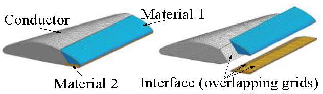
Figure 1: Targets with non-uniform thickness materials.
To address the above-mentioned problems, an efficient and universal method is presented in this paper. Ray tracing is performed inside the material to obtain the radar cross-section (RCS) of targets with non-uniform thickness materials. Unlike the existing acceleration algorithms, the proposed approach employs the Embree3 ray tracing library, an open-source library specifically designed for image rendering, to realize model building and ray intersection. For overlapping grids at the interface, the intersection information is determined by tracing twice in multiple scenes, which avoids complex overlapping grid processing.
This paper successfully combines Embree3 with the SBR method. The introduction of Embree3 significantly improves the efficiency of ray tracing. Moreover, the problem of overlapping grids is ingeniously solved through the multi-scene method. The proposed method has much higher efficiency and stronger applicability than the existing methods.
II. RAY TRACING INSIDE MATERIALS BASED ON EMBREE3
The common SBR method mainly includes modeling, ray tracing, field tracing, and far-field integration. The specific process of the SBR method based on Embree3 is as follows.
A. Modeling
In contrast to the traditional SBR method with surface tracing, internal ray tracing requires multiple sets of grids to differentiate between various materials. Besides, multiple scenes need to be created to solve the problem of overlapping grids.
There are three types of objects in Embree3, including device object (do), scene object (so), and geometry object (GO). Each object has an independent ID. As shown in Fig. 2, GO is the first level. Each GO corresponds to an independent set of grids, like GO 1, GO 2, and GO 3. The SOs are the second level, corresponding to different scenes. Each SO can include multiple GOs, like SO 1, SO 2, SO 3, and SO 4. DO is the third level. Each DO can include multiple SOs, like DO 1. Normally, the traditional SBR method with surface tracing requires only one scene (SO 1). However, tracing inside the materials requires multiple scenes (SO 1, SO 2, SO 3, and SO 4) to deal with the overlapping grids. The usage of multiple scenes will be described in Section IID.
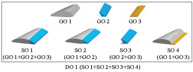
Figure 2: Objects in Embree3.
B. Ray tracing
Ray tracing is the key to the accuracy and efficiency of the SBR method. The process of ray tracing based on Embree3 is described in detail below.
The first step is to determine the initial ray tube on the face of the bounding box, which is obtained through the function “RtcGetSceneBounds” defined in Embree3. The incident direction of the initial ray tube changes with coordinate rotation.
The second step is to find the intersections. Embree3 provides an efficient function “RtcIntersect” to obtain the intersection. The function “RtcIntersect” is based on the bounding volume hierarchy (BVH) algorithm [8] and the Möller-Trumbore algorithm [9].
Figure 3 shows that the BVH is a binary tree, where each node represents a bounding box containing grids. The root node represents the bounding box of the whole scene, and the other nodes represent the sub-bounding box. Intersection detection begins at the root node, checking if the ray overlaps with the bounding box. This process recursively continues until reaching the bounding box of the leaf node. In contrast to kd-tree, which divides regions based on space before intersection, BVH divides bounding boxes based on grids in the process of intersection. The Möller-Trumbore algorithm is a fast method to find the intersection of rays and triangles in space. It is used to obtain the actual intersection between the ray and the grids in the minimum bounding box.
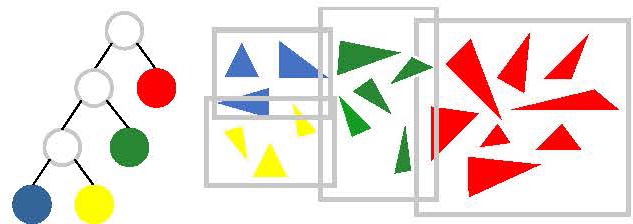
Figure 3: BVH structure.
The combination of the BVH algorithm and the Möller-Trumbore algorithm significantly enhances the efficiency of ray intersection. Besides, Embree3 defines a structure “RTCRayHit” for storing incident and intersection information. As shown in Fig. 4, the structure “RTCRayHit” with incident information is passed as input to the function “RtcIntersect”, and the intersection information is returned to the structure.
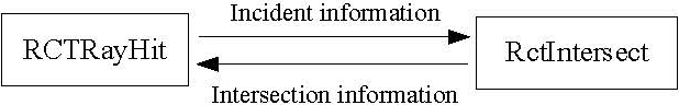
Figure 4: Finding the intersections.
The third step is to determine the reflection and transmission information. Figure 5 shows that the intersection information in “RTCRayHit” is used to obtain reflection and transmission information employing equations (1)-(6).
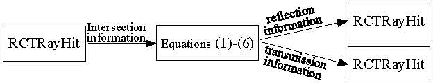
Figure 5: Determining the reflection and transmission information.
As shown in Fig. 6, when a ray hits the interface between the free space (Region 0) and the material (Region 1), a transmitted wave and a reflected wave will be generated at the intersection. The incident wave vector and the transmitted wave vector are:
| (1) | ||||
| (2) |
where is the incident angle, is the wave vector in free space, is the transverse component, and is the longitudinal component. According to the phase matching condition [10], the following can be obtained:
| (3) | |||
| (4) |
The transmission angle can be calculated after obtaining by solving equations (3) and (4) with the following:
| (5) |
According to the Snell’s law, the reflection angle is equal to the incident angle :
| (6) |
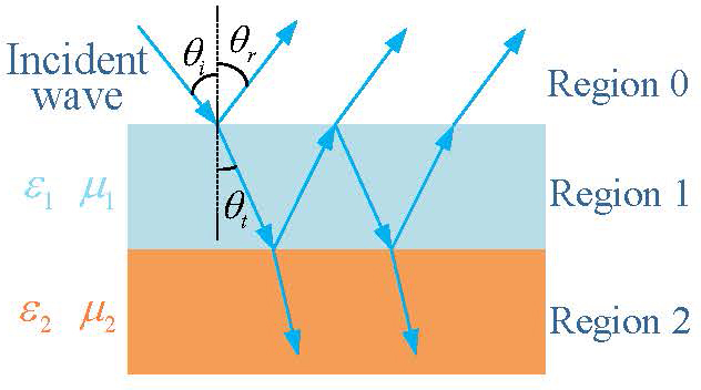
Figure 6: Wave propagation inside the materials.
The fourth step is to determine whether to continue tracing. The maximum tracing times and the minimum energy limit are set as the end conditions. Moreover, ray tracing will also stop when there is no intersection. If the end condition is not met, the operation in the second step will be repeated by treating the reflected or transmitted ray as the new incident ray.
C. Field tracing and far-field integration
Field tracing and ray tracing are performed simultaneously. The attenuation coefficient of the material can be calculated using equations (3) and (4). The calculation method of the reflection and transmission coefficients is provided in [11] and listed as follows:
| (7) |
where , , , and are the reflection and transmission coefficients of TE and TM waves, respectively. The reflected and transmitted electric fields at the intersection can be calculated as:
| (8) |
After performing ray tracing and field tracing for all ray tubes, the effective ray tubes are selected for far-field integration. Gordon’s method is adopted in this paper for integration [12]. The RCS of the target can be obtained by superimposing the scattering field of all effective ray tubes.
D. Ray tracing in multiple scenes
Overlapping grids make it challenging to accurately and directly determine the correct material parameters required for reflection and transmission calculations. As shown in Fig. 7, there are four different intersections for a ray tube. Due to the overlapping grids at Point 2 and Point 3, all four intersections are located on the grid of GO 2, which affects the acquisition of correct material parameters. To ensure accurate and efficient ray tracing, the multiple scenes as shown in Fig. 2 are used to determine the precise GO where the intersection occurs. The specific process is as follows.
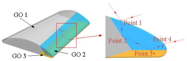
Figure 7: Intersections of a ray tube.
In this multi-scene method, each ray tracing needs to be carried out twice in different SOs. As shown in Fig. 8, the intersection of the first tracing is on GO 2. Thus, the second tracing is made in SO 2, which does not contain GO 2. The distance d between the two intersections is calculated when both tracings have an intersection. According to the position of the second intersection and the distance d, the actual position of the intersection can be determined.
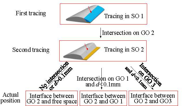
Figure 8: Ray tracing in multiple scenes.
The multi-scene method effectively solves the problem of overlapping grids. Despite a significant increase in intersection points, the overall method remains efficient due to the powerful performance of Embree3 and the avoidance of overlapping grid processing. Furthermore, this multi-scene method is not limited by model shape and mesh quality.
III. SIMULATIONS AND DISCUSSION
The accuracy and efficiency of the proposed ray tracing method were investigated through the following four examples. All the simulations were performed on a workstation with two Intel (R) Xeon (R) CPU Gold-6248R.
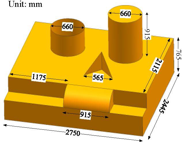
Figure 9: Dimensions of the SLICY model.
A. SLICY model
A conductor SLICY model as shown in Fig. 9 was simulated first. The RCS from the SBR method in CST was compared with the proposed SBR method. The incident angle varied in the range of for , polarization. The frequency was 10 GHz, and the electrical size was about . The high degree of consistency between the two results shown in Fig. 10 validates the accuracy of the ray tracing method in this paper. Table 1 presents the computation cost, demonstrating the high efficiency of the proposed ray tracing method.
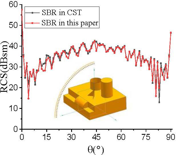
Figure 10: RCS of the SLICY model.
Table 1: Computation time of the SLICY model
| SLICY model | SBR in this paper | SBR in CST |
| Time | 19 s | 24 s |
Table 2: Computation time of coated trihedral
| Coated trihedral | SBR in this paper | SBR in [5] | FEM |
| Time | 16 s | 2174 s | 1.8 h |
B. Trihedral coated with thick material
A trihedral coated by a material with a thickness of was analyzed. The parameters were . The incident angle varied in the range of for , polarization, and the frequency was 6 GHz. Figure 11 compares the results of the SBR method in this paper with the FEM in HFSS. The results are quite consistent, demonstrating the accuracy of the SBR method in this paper when there is material in the target.
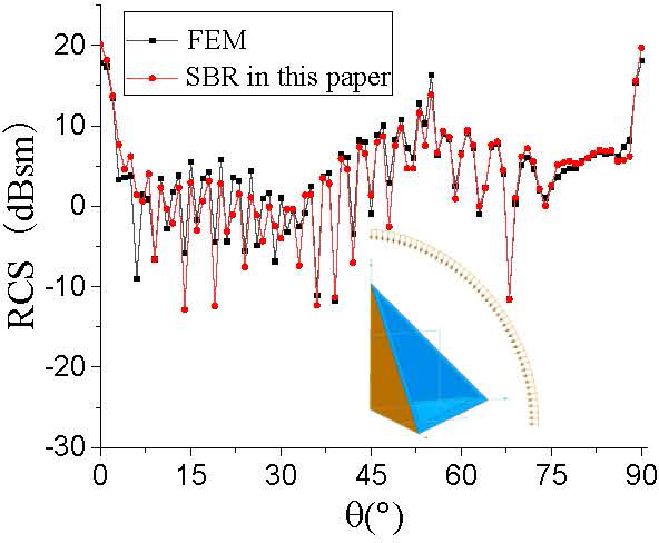
Figure 11: RCS of coated trihedral.
Table 2 compares the computation time of the SBR method in this paper with the SBR method in [5], which uses kd-tree for the same model. It can be seen that the efficiency of the proposed ray tracing is much higher than that of the traditional acceleration method.
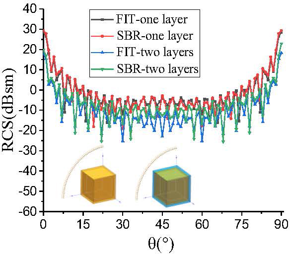
Figure 12: RCS of a coated cube.
C. Cube coated with thick materials
The RCS of a cube coated with thick materials was calculated. The size of the cube was . Two different cases were considered. In one case, the cube was coated with a single layer of material, and the thickness was , . In the other case, the cube was coated with two-layer material, and the thickness of each layer was , for the inner layer, and for the outer layer. For both cases, the incident angle varied in the range of for , polarization, and the frequency was 3 GHz. The RCS results of the two cases are shown in Fig. 12. The reference results are from the finite integration technique (FIT) in CST.
It can be seen from Fig. 12 that the results of the two methods are consistent, indicating that the SBR method proposed in this paper is still accurate when dealing with multi-layer thick materials. Table 3 shows that the computation time of the proposed SBR method is significantly lower than that of the FIT.
Table 3: Computation time of a coated cube
| Coated | Cube | One Layer | Two Layers | |
|---|---|---|---|---|
| SBR | FIT | SBR | FIT | |
| Time | 13 s | 3.5 h | 20 s | 4.6 h |
D. Combination of conductor and materials
The fourth model was a combination of three parts. The size of the entire model was about . Each part was of non-uniform thickness. There were two different cases. In case 1, all three parts were conductors. In case 2, part 1 was a conductor, part 2 was a material with , , and part 3 was a material with , . For both cases, the incident angle varied in the range of for , polarization, and the frequency was 3 GHz.
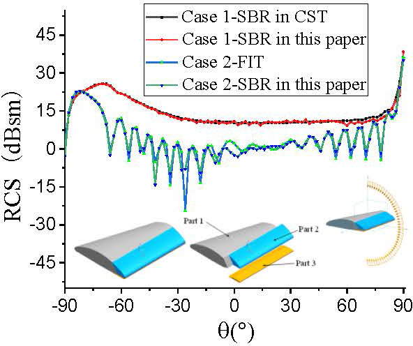
Figure 13: RCS of three-part combination.
Table 4: Computation time of combination model
| Combination | Case 1 | Case 2 | ||
|---|---|---|---|---|
| SBR | SBR in CST | SBR | FIT | |
| Time | 3 s | 3 s | 15 s | 6.8 h |
Figure 13 shows the RCS results of the three-part combination. The reference results are from the SBR method in CST for case 1 and the FIT in CST for case 2. It can be observed that the results are quite consistent for both cases. The computation time is shown in Table 4. This example further illustrates the accuracy and high efficiency of the proposed SBR method when dealing with targets with non-uniform thickness materials since the SBR method in CST can only be used for conductor.
IV. CONCLUSION
An accelerated ray tracing method is studied in this paper. The scattering of target with non-uniform thickness materials is calculated by ray tracing inside the materials. The Embree3 ray tracing library is introduced to improve the efficiency of ray tracing. Moreover, a multi-scene method is proposed to determine the intersection position, which avoids overlapping grid hidden processing. Experimental results demonstrate and validate that the proposed method has higher efficiency and stronger applicability than the existing algorithms.
REFERENCES
[1] R. Gholami and V. Okhmatovski, “Surface–volume–surface EFIE formulation for fast direct solution of scattering problems on general 3-D composite metal–dielectric objects,” IEEE Trans. Antennas Propagat., vol. 68, no. 7, pp. 5742-5747, July 2020.
[2] B. Stupfel, “Homogenization of a multilayer coating: Application to model-order reduction,” IEEE Trans. Antennas Propagat., vol. 69, no. 3, pp. 1528-1534, Mar. 2021.
[3] W. Chen, L. Wang, Z. Wu, M. Fang, Q. Deng, A. Wang, Z. Huang, X. Wu, L. Guo, and L. Yang, “Study on the electromagnetic scattering characteristics of high-speed target with non-uniform plasma via the FCC-FDTD method,” IEEE Trans. Antennas Propagat., vol. 70, no. 7, pp. 5744-5757, July 2022.
[4] Z. Xie, Z. Liang, H. Yue, and P. Gao, “A shooting and bouncing ray method for dielectric media,” in 2017 International Applied Computational Electromagnetics Society Symposium (ACES), pp. 1-3, 2017.
[5] Y. Huang, Z. Zhao, X. Li, Z. Nie, and Q. H. Liu, “Volume equivalent SBR method for electromagnetic scattering of dielectric and composite objects,” IEEE Trans. Antennas Propagat., vol. 69, no. 5, pp. 2842-2852, May 2021.
[6] H. Ding, P. Gao, Y. Tao, and H. Lin, “Kd-tree based fast facet visibility test in iterative physical optics,” in 2013 IEEE Antennas and Propagation Society International Symposium (APSURSI), Orlando, FL, pp. 1788-1789, 2013.
[7] J. Huo, L. Xu, X. Shi, and Z. Yang, “An accelerated shooting and bouncing ray method based on GPU and virtual ray tube for fast RCS prediction,” IEEE Antennas Wireless Propagat. Lett., vol. 20, no. 9, pp. 1839-1843, Sep. 2021.
[8] H. Liu, B. Wei, and H. Wang, “A fast shooting and bouncing ray algorithm for electromagnetics scattering based on bounding volume hierarchy,” in 2023 IEEE 7th International Symposium on Electromagnetic Compatibility (ISEMC), Hangzhou, China, pp. 1-3, 2023.
[9] T. Möller and B. Trumbore, “Fast, minimum storage ray-triangle intersection,” Journal of Graphics Tools, vol. 2, no. 1, pp. 21-28, 1997.
[10] P. H. Pathak and R. J. Burkholder, Electromagnetic Radiation, Scattering, and Diffraction. Hoboken, NJ: Wiley-IEEE Press, 2022.
[11] W. C. Chew, Waves and Fields in Inhomogeneous Media. Hoboken, NJ: Wiley-IEEE Press, 1995.
[12] W. Gordon, “Far-field approximations to the Kirchoff-Helmholtz representations of scattered fields,” IEEE Trans. Antennas Propagat., vol. 23, no. 4, pp. 590-592, July 1975.
BIOGRAPHIES

Yi Zhu was born in Sichuan, China, in 1996. He received the B.S. and M.S. degrees in electromagnetic field and microwave technology from Northwestern Polytechnic University, Xi’an, China, in 2018 and 2021, respectively, where he is currently pursuing the Ph.D. degree. His research interests include computational electromagnetics.

Gao Wei was born in Shandong, China, in 1963. He received the B.S. and M.S. degrees in electromagnetic field and microwave technology from Northwestern Polytechnic University, Xi’an, China. He is currently a professor with the School of Electronics and Information in Northwestern Polytechnic University. His current research interests include antenna theory and techniques, microwave measurement, and microwave application.

Jianzhou Li was born in Shaanxi, China, in 1972. He received the Ph.D. degree from Northwestern Polytechnic University, Xi’an, China, in 2005. He received a P.D. degree in Surrey Satellite Center in University of Surrey, UK, in 2009. He is currently an associate professor with the School of Electronics and Information in Northwestern Polytechnic University. His current research interests include antenna theory and techniques, and computational electromagnetics.
ACES JOURNAL, Vol. 39, No. 6, 527–532
doi: 10.13052/2024.ACES.J.390606
© 2024 River Publishers