Outdoor Wi-Fi Dual-band Dual-polarized Base Station Antenna Design
Yida Fan, Lijuan Li, Ravi K. Arya, Xianghua Ma, Shiyuan Kong, and Junwei Dong
1School of Optoelectronic Engineering
Changchun University of Science and Technology, Changchun, Jilin, 130022, China
FanYD_cust@outlook.com, custjuan@126.com
2Xiangshan Laboratory
Zhongshan Institute of Changchun University of Science and Technology, Zhongshan, Guangdong, 528437, China
custjuan@126.com, raviarya@cust.edu.cn, 184217177@qq.com, dongjunwei@163.com
3EMed Technology Co. Ltd
EMed Technology Co. Ltd, Zhongshan, Guangdong, 528437, China
18666980616@163.com
Submitted On: April 24, 2024; Accepted On: December 4, 2024
ABSTRACT
In this manuscript, a dual-band and dual-polarized coupled patch array antenna operating at 2.45 GHz and 5.8 GHz for outdoor Wi-Fi applications is proposed. Two sets of antenna arrays made of four-element stacked patches act as main radiators. The height of this antenna is 0.04, which is much smaller than the general size of other low-profile antennas. The arrays are fed by two feed ports which are used to separately feed vertical and horizontally polarized signals with stable port isolation. The antenna structure also employs a duplex filter to filter 2.4-2.484 GHz and 5.1-5.9 GHz operating band frequencies. The measured impedance bandwidths of the prototype antenna structure are 2.41-2.484 GHz and 5.1-5.9 GHz, respectively. The isolation between the two ports is greater than 20 dB, and the cross-polarization level is better than 20 dB in the operating bands. In addition, the average gain of the prototype antenna is approximately 13 dBi in horizontal and vertical polarization. Overall, because of the stable structure, high reliability, small size, and light weight of the patch antenna, the outdoor base station antenna has a huge potential market value, this antenna is a good candidate for commercial outdoor Wi-Fi applications.
Index Terms: Access point, antenna array, dual-band, dual-polarized patch antenna, low profile.
I. INTRODUCTION
With the popularity of 4G communication technology and the rise of 5G communication, Wi-Fi technology has been widely used. Wi-Fi is a superset of the IEEE 802.11 standards for communication of local area networked devices spanning over several tens of meters [1]. Commercial Wi-Fi antennas demand different features such as low cost, small size, easy manufacturability, and good performance. However, attaining all these features in a single antenna demands good engineering skills.
A dual-band dual-polarized antenna is a kind of antenna that has been widely used in base station communications in recent years. It can not only integrate the signal transmission capability of the two frequency bands into one structure for size reduction, but also has many advantages such as wide broadband, strong anti-interference ability, low power consumption, and great channel capacity, which are desired features for commercial Wi-Fi applications.
The main antenna structures used for dual polarization include cross dipole antenna, slot antenna, and patch antennas [2, 3, 4, 5, 6]. Cross-dipole antennas have high cross-isolation and good broadband performance. Still, the design of such antennas occupies more space, which is not conducive to the miniaturization of antennas [7, 8, 9]. The slot antenna, on the other hand, has the advantages of planar feed structure, wideband, and high isolation, but has poor cross-polarization properties [10, 11, 12].
Compared with the above antennas, the patch antenna has a small footprint, low cost, and can achieve wideband and better port isolation by stacking patch antennas [13, 14], so it is a good candidate as an array antenna element. For example, it is proposed [15] that the antenna realizes the dual-band dual-polarization antenna and has a high degree of isolation between ports.
The design of dual-polarized 4-unit array antenna with 1-4 power dividers provided in [6] and [10] serves as a reference for the antenna design. According to the standard of Wi-Fi frequency band, this manuscript designs a new low-profile dual-polarized coupled patch antenna unit and a low-passband stop filter, and realizes the dual-frequency dual-polarized patch array antenna for outdoor Wi-Fi base stations. High isolation and low cross polarization are obtained in the operating frequency band. To validate the design model, a prototype antenna was fabricated and measured. The simplified block diagram of the antenna structure is shown in Fig. 1 where HF means high-frequency and LF means low-frequency. The antenna elements and arrays are discussed in detail below.
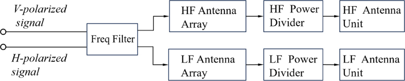
Figure 1: Antenna structure block diagram.
II. DESIGN OF DUAL-POLARIZATION ANTENNA UNIT
The design of patch antenna must first determine the substrate material used and the operating frequency. According to the definition of Wi-Fi operating frequency band, this manuscript designs the patch antenna with operating frequency of 2.4-2.48 GHz and 5.1-5.8 GHz, respectively, using substrate materials with thickness of 0.74 mm, 2.45, tan 0.001. The length and width of the rectangular patch can be calculated by some numerical formulas:
| (1) |
where c is the speed of light, is dielectric constant, is resonant frequency.
The effective dielectric constant () is calculated according to the substrate material height (), dielectric constant () and the calculated width () of the patch antenna:
| (2) |
The actual length of the patch antenna is calculated by (3):
| (3) |
The patch antenna works in dual polarization mode, its dimension is constrained to equal side length. Due to the small thickness of the substrate material, the upper layer element is used as a coupled antenna with a dimension of to expand the bandwidth of the antenna. Finally, through simulation and optimization, the following low-frequency antenna array structure is obtained.
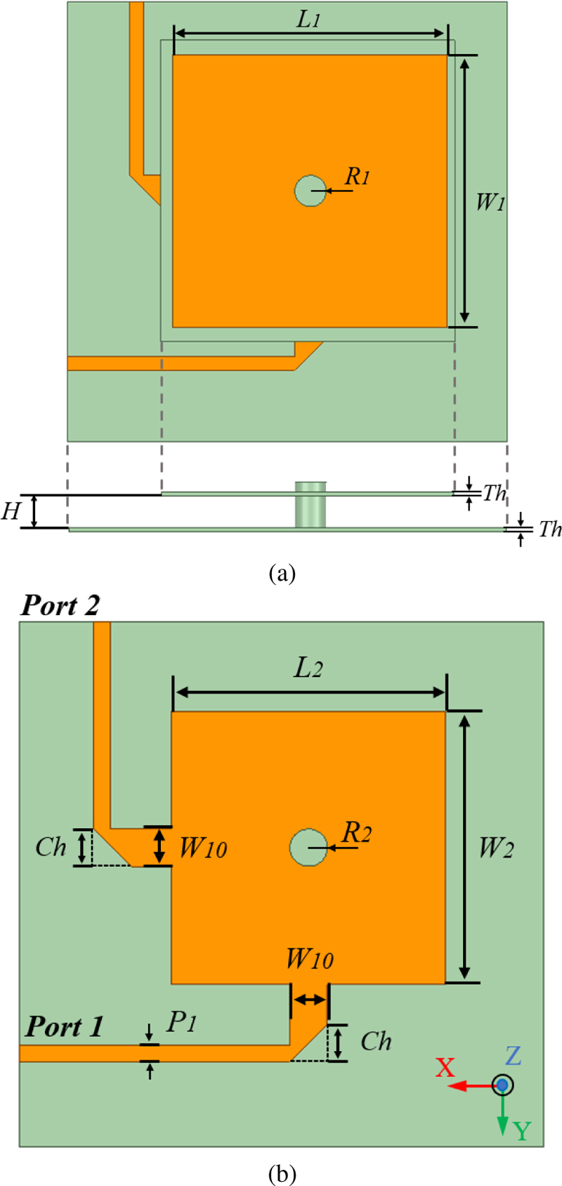
Figure 2: Low-frequency antenna element: (a) top structure and (b) bottom structure.
Figure 2 shows the low-frequency antenna element of the proposed antenna. The low-frequency antenna element operates at a frequency of 2.41-2.484 GHz. The antenna primarily consists of two layers: upper and lower patches separated by a 5 mm gap. The upper patch measures 43.5 mm 43.5 mm, while the lower patch measures 36.5 mm 36.5 mm. Both patches are linked by a common support column, with foam material inserted between them to stabilize the antenna unit. The two feed ports of the antenna have a 90 angle so that port 1 inputs a vertically polarized signal and port 2 inputs a horizontally polarized signal. The parameter values defined in Fig. 2 are as follows (unit: mm) : 43.5, 1.2, 2.2, 5, 36.5, 5, 5, 0.74.
All antenna simulations were conducted utilizing CST Studio Suite. Hexahedral meshing is applied to the antenna, and the number of meshing for each wavelength is adjusted so that the details in the structure are included. The performance of the antenna is simulated by using a time-domain solver Finite Integration Technique. In Fig. 3, the simulated S-parameter of the antenna element is depicted. The frequency range exhibiting a return loss exceeding 10 dB spans from 2.41 GHz to 2.484 GHz, satisfying the criteria for the low-frequency band. Moreover, the isolation between the two ports surpasses 25 dB.
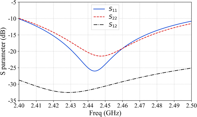
Figure 3: Low-frequency antenna S-parameter.
Figure 4 shows the simulated co-planar polarization and cross-polarization of the low-frequency antenna element at the and cuts. These plots show that port 1 and port 2 have good cross-isolation.
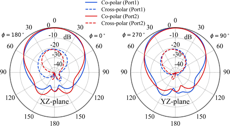
Figure 4: Low-frequency antenna element radiation pattern at 2.45 GHz.
According to equations (1) and (3), the basic size of the high frequency patch antenna can be calculated. The lower patch of the high-frequency antenna is arranged with inward-facing grooves for adjusting the feed position. The grooves can also expand the bandwidth and reduce the impedance mismatch through reasonable parameter optimization.
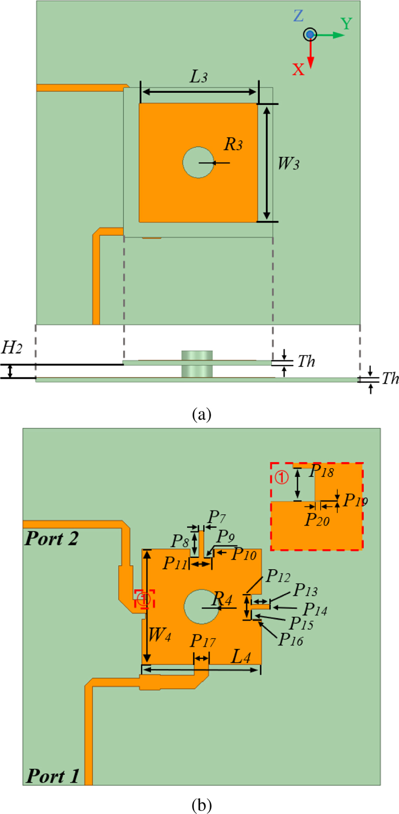
Figure 5: High-frequency antenna unit: (a) top structure and (b) bottom structure.
Figure 5 shows the high-frequency antenna element of the proposed design, operating within the frequency range of 5.1 GHz to 5.9 GHz. The overall size of the antenna is 52 mm 52 mm, and the substrate is 0.74 mm thick. The antenna element consists of two layers of patches, the upper layer of patch antenna size is 19 mm 19 mm while the lower base size is 16.83 mm 17.325 mm, separated by a 2 mm gap. The coupled upper and lower patches in this manner help to expand the bandwidth effectively. The parameter values defined in Fig. 5 are as follows (units: mm) : 19, 1.2, 2, 0.74, 16.83, 17.325, 0.63, 3.876, 1.2768, 1.224, 3.18, 3.57, 2.73, 0.612, 1.479, 1.4175, 2, 0.78, 0.02, 0.1168.
Figure 6 shows the simulated S-parameter of the antenna element. The return loss of the antenna in the range of 5.1-5.9 GHz is greater than 9 dB. It meets the requirements of the high-frequency operating band, the isolation between the two ports exceeds 20 dB, demonstrating satisfactory performance characteristics.
The radiation pattern of port 1 and port 2 of the antenna at 5.1-5.9 GHz is simulated, which has a good cross isolation. The co-planar and cross-polarization of the simulated antenna radiation pattern at the and sections are shown in Fig. 7.
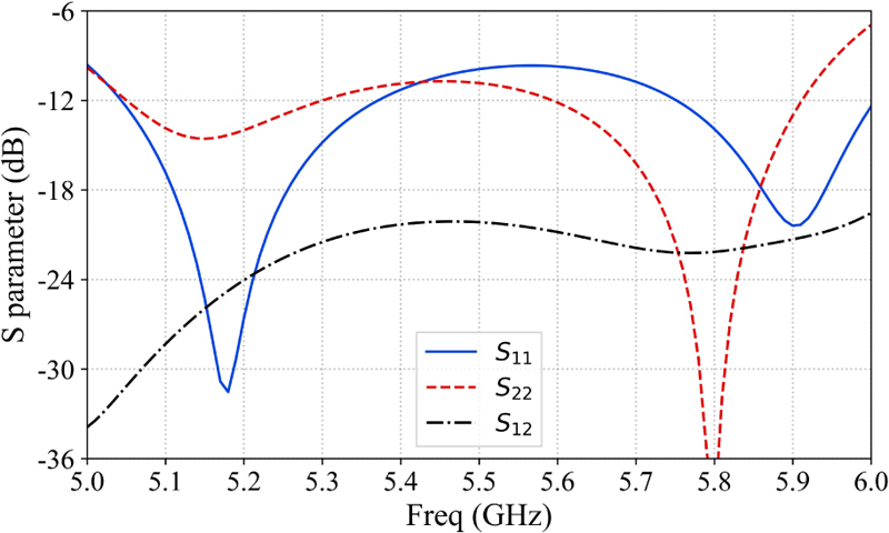
Figure 6: High-frequency antenna S parameter.
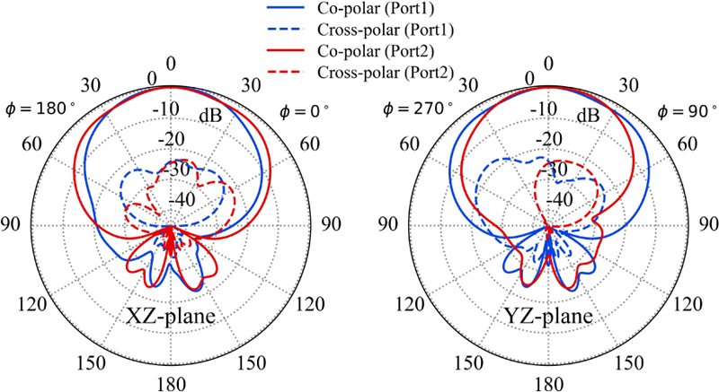
Figure 7: High-frequency antenna radiation pattern at 5.8 GHz.
III. DUAL-POLARIZED DUAL-BAND ANTENNA ARRAY
Base station antennas typically require a narrower beam and higher gain. Based on the antennas proposed in section II., the low-frequency four-element dual-polarized antenna array and the high-frequency four-element dual-polarized antenna array are designed, constructed, and measured. Each of these antenna arrays is fed by two 1-to-4 power dividers. Each polarized port provides simultaneous signal distribution in the 2.41-2.484 GHz and 5.1-5.9 GHz bands via a frequency selector. The antenna geometry including the low-frequency antenna array, high-frequency antenna array, power divider, and frequency selector is shown in Fig. 8.
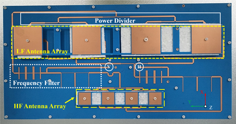
Figure 8: Prototype of the dual-frequency dual-polarization antenna.
Figures 9 (a) and 9 (b) show the simulated S-parameters of the power divider for low and high frequencies attached to its geometry. Only the combination of T-junction and 1/4 wavelength converter is used through the cascade of two power splitters to divide the energy into four equal parts in the structure. The impedance of each part of the power divider can be calculated from (4):
| (4) | ||||
where is impedance of T-junction 1 output port, is impedance of T-junction 2 output port, is impedance of the T-junction input port, is characteristic impedance of 1/4 wavelength converter.
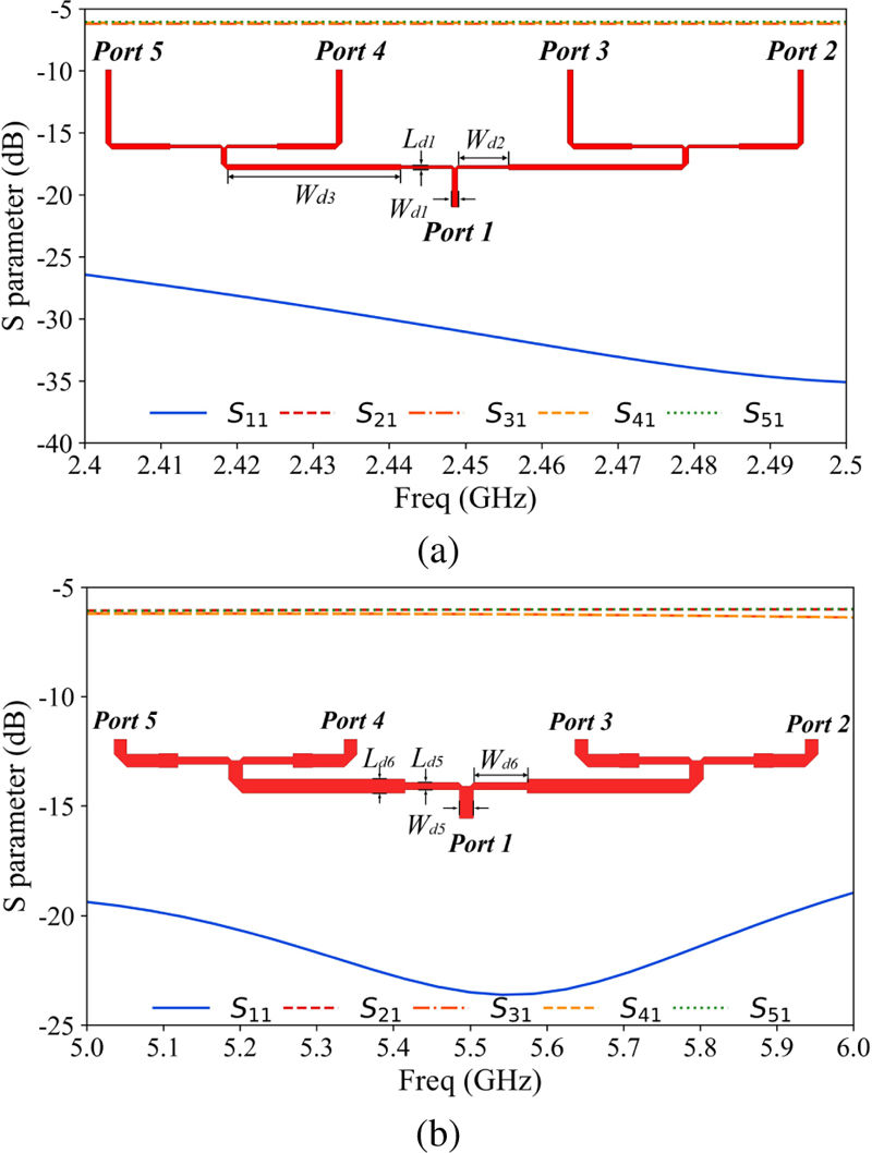
Figure 9: Simulated S-parameters of power divider: (a) simulated S-parameters of the low-frequency power divider and (b) simulated S-parameters of the high-frequency power divider.
The parameter values defined in Fig. 9 (a) are as follows (unit: mm) : 2.2, 19.9, 67.9, 1.25. The parameter values defined in Fig. 9 (b) are as follows (unit: mm) : 2.2, 8.4, 1.16, 2.2.
To optimize the efficiency of the dual-band antenna and make the single port provide the matching signal frequency to the low-frequency antenna array and the high-frequency antenna array at the same time, a duplex filter is designed in this work. The filter consists of a low-pass filter and a band-stop filter.
The filter for sorting the low-frequency signal is a step-impedance low-pass filter. The passband cutofffrequency is 2.6 GHz. According to the value table of the prototype components of the low-pass filter, it can be found that , , , , , , . According to the short transmission line approximate equivalent circuit theory, the length of inductance and capacitance section is calculated by (5):
| (5) |
where is the filter impedance, and and are the normalized component values () of the low-pass prototype. is a microstrip line high impedance, is a microstrip line low impedance.
Under the constraint of (6):
| (6) |
the reference values of microstrip line impedance and length can be obtained. The structure in Fig. 10 can be obtained by further simulation.
The filter for sorting the high frequency signal is a truncated band-stop filter with a cutoff frequency of 2.45 GHz. The filter prototype is transformed into a truncated microwave filter by using the Richard transform and Koloda identity relation, and its structure is shown in the Fig. 10. The structure ensures that the low-frequency signal of 2.41-2.484 GHz is correctly fed into the low-frequency antenna array while the high-frequency signal of 5.1-5.9 GHz is correctly fed into the high-frequency antenna array, and the signal can pass almost without loss within the matched frequency. Low-frequency signals and high-frequency signals are highly isolated. Figure 10 shows the structure of the duplex filter, and the parameter values defined in the figure are as follows (unit: mm): 3, 35, 1.5, 0.8, 44, 2, 19, 20.5, 1, 1.5, 21.7, 0.6, 22.7.
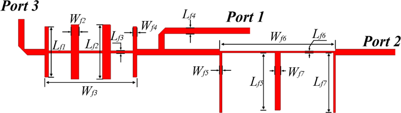
Figure 10: Geometry of the duplex filter.
As shown in Fig. 10, port 1 serves as the signal input port, while port 2 and port 3, respectively, function as the high-frequency and low-frequency signal outputs. The S-parameters of the duplex filter within the frequency band of 2.41-2.484 GHz and 5.1-5.9 GHz are shown in Fig. 11. It can be seen in Fig. 11 that the return loss of the duplex filter is greater than 10 dB in the dual frequency bands, and the high-frequency and low-frequency signals are separated smoothly after passing through the duplex filter and are transmitted to the matching port.
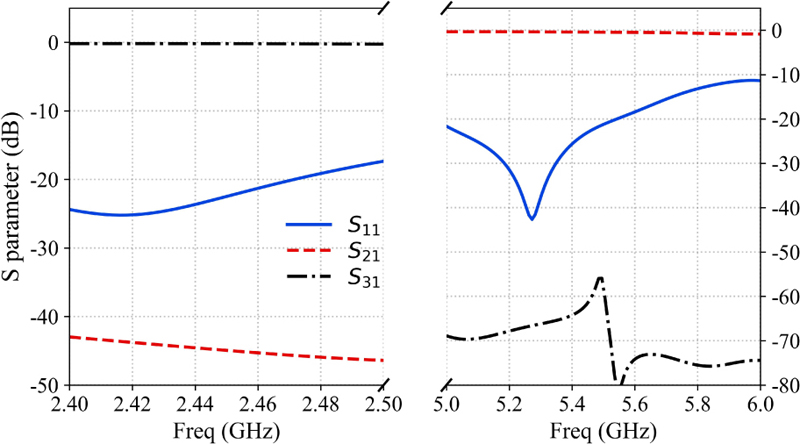
Figure 11: Simulated S-parameters of the duplex filter.
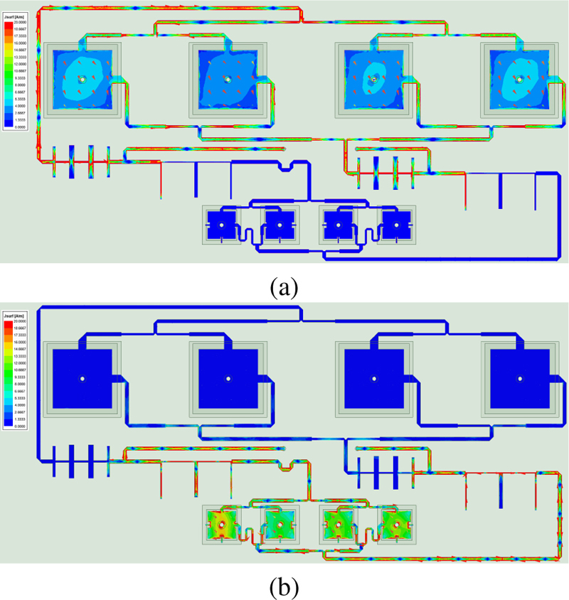
Figure 12: Current distribution of antenna: (a) currents at 2.45 GHz and (b) currents at 5.8 GHz.
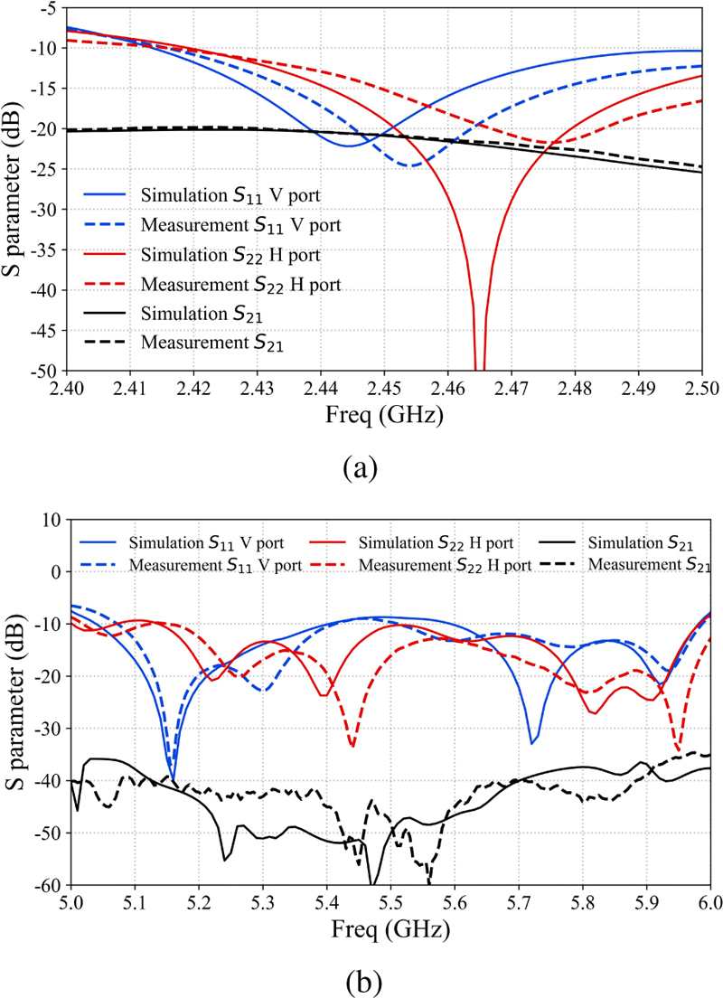
Figure 13: S-parameters of the proposed antenna: (a) low-frequency band and (b) high-frequency band.
After optimization, the optimized distance between the low-frequency antenna elements is set to be ( is the wavelength at 2.5 GHz) while the distance between the high-frequency antenna elements is set to be ( is the wavelength at 5.45 GHz). The current distribution of the antenna is shown in the Fig. 12. The signal leads to different antenna array elements according to different frequencies, the surface of the patch has a stable current distribution.
The measured and simulated S-parameters of the proposed outdoor Wi-Fi antenna are shown in Fig. 13. It is observed that the dual-frequency dual-polarized antenna achieves bandwidths of 2.41-2.484 GHz and 5.1-5.9 GHz. Furthermore, the isolation between the two ports remains consistently superior to 20 dB across the entire operational bandwidth.
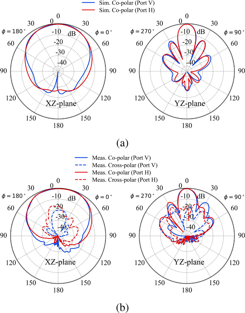
Figure 14: Simulated and measured radiation patterns of the proposed antenna: (a) simulated radiation pattern at 2.45 GHz and (b) measured radiation pattern at 5.8 GHz.
The proposed antenna was measured by a robotic far-field measurement system. The simulated and measured results of co-planar polarization and cross-polarization of two polarizations are shown in Fig. 14. The gain of the proposed antenna is shown in Fig. 15 (a).
Table 1: Comparison of proposed and reference antenna
| Ref. |
|
|
|
|
|
|
|
||||||||||||||
| [11] | 3.14-3.81 | 1 | 0.450.45 | 0.12 | 0.8 | 8.1 | 43 | ||||||||||||||
| [15] |
|
1 | 0.540.54 | 0.13 | 0.8 |
|
30 | ||||||||||||||
| [6] |
|
4 | 3.060.94 | 0.11 | 1 |
|
25 | ||||||||||||||
| [10] | 1.69-2.5 | 4 | 3.171.12 | 0.13 | 1 | 13.9 | 27 | ||||||||||||||
| Proposed |
|
4 | 2.61.4 | 0.04 | 0.74 |
|
|
Table 1 shows the performance of this antenna compared with other dual-polarized antennas. [11], [15] has a higher isolation, but limited gain and a higher profile of 0.12. The proposed patch antenna has a high isolation of 35 dB in the high frequency band and a low profile of 0.04. In the case of similar gain, the height of the antenna proposed in this manuscript is much smaller than the design of the literature [6], [10]. More importantly, the substrate of this design is thinner and smaller in size, and it has excellent isolation. Therefore, such antennas are preferable in applications requiring low profile and lightweight miniaturization.
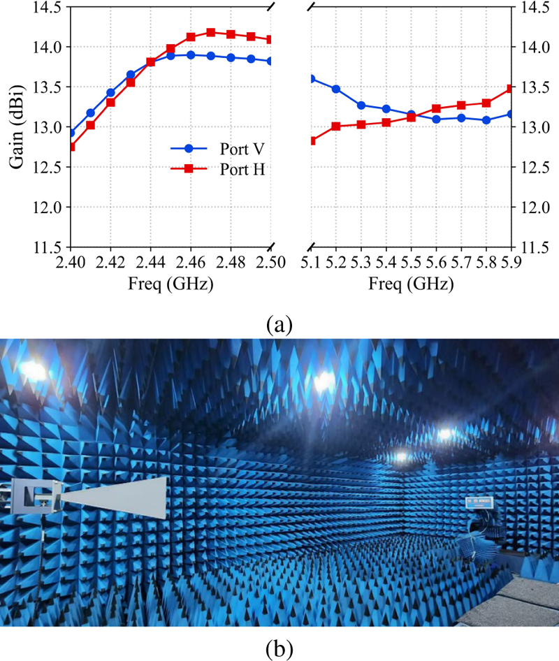
Figure 15: Measured gains for the proposed antenna: (a) measured gains for port V and port H and (b) antenna measured in chamber.
IV. CONCLUSION
A novel outdoor Wi-Fi antenna with dual-band and dual-polarization capability is proposed in the manuscript. This proposed antenna uses the coupling of the upper and lower layers of two patch antennas to extend the working bandwidth of the antenna, so that it can meet the working requirements of 2.4 GHz and 5 GHz band Wi-Fi. The substrate used in the design is a kind of self-developed blue flexible material, which has the characteristics of light weight and low cost, and the thickness of the substrate material used is less than that of the general material. The fabricated prototype antenna achieves operation in the 2.41-2.484 GHz and 5.1-5.9 GHz range, and maintains isolation of better than 20 dB (2.4 GHz band) and 35 dB (5 GHz band) between its two ports. For vertical polarization, the antenna gain is 13.88 dBi at 2.45 GHz and 13.08 dBi at 5.8 GHz, while the horizontal polarization provides a gain of 13.97 dBi at 2.45 GHz and 13.29 dBi at 5.8 GHz, the proposed antenna achieves stable and high gain in both polarization cases. The height of this antenna is 0.04, which is much smaller than the general size of other low-profile antennas. Such antennas are preferable in applications requiring low profile and lightweight miniaturization, and has a huge potential market value.
ACKNOWLEDGMENT
This work is supported by the Major Science and Technology Project of Zhongshan City, under grant No. (2022A1012).
REFERENCES
[1] Z. N. Chen, X. Qing, T. S. P. See, and W. K. Toh, “Antennas for WiFi connectivity,” Proceedings of the IEEE, vol. 100, no. 7, pp. 2322-2329, 2012.
[2] W. Zhou, S. Abdullah, J. Labossiere, N. Javanbakht, J. Shaker, G. Xiao, and R. E. Amaya, “Impact of amplitude and phase imbalance on dual differential fed patch antenna with high isolation,” IEEE Open Journal of Antennas and Propagation, vol. 3, pp. 1227-1233, 2022.
[3] J. Chen, M. Berg, K. Rasilainen, Z. Siddiqui, M. E. Leinonen, and A. Pärssinen, “Broadband cross-slotted patch antenna for 5G millimeter-wave applications based on characteristic mode analysis,” IEEE Transactions on Antennas and Propagation, vol. 70, no. 12, pp. 11277-11292, 2022.
[4] Y. Sun, P. Liu, and S. Zhang, ‘‘A wideband low-profile dual-polarized antenna with transmission characteristics,” in 2023 IEEE-APS Topical Conference on Antennas and Propagation in Wireless Communications (APWC), pp. 125-127,2023.
[5] X. Qin and Y. Li, “Dual-wideband dual-polarized gridded patch antenna array for 5G millimeter-wave systems,” in 2022 International Symposium on Antennas and Propagation (ISAP), pp. 55-56, 2022.
[6] L. Y. Nie, X. Q. Lin, Y. J. Chen, J. Zhang, B. Wang, Z. Q. Yang, and Y. Fan, “A low-profile coplanar dual-polarized and dual-band base station antenna array,” IEEE Transactions on Antennas and Propagation, vol. 66, no. 12, pp. 6921-6929,2018.
[7] M. Milijic and B. Jokanovic, “Dual polarized crossed slot antennas proposed for IoT applications,” in 2023 10th International Conference on Electrical, Electronic and Computing Engineering (IcETRAN), pp. 1-6, 2023.
[8] P. Gao, Y. Xu, H. Ma, C. Wang, C. Sun, and J. Tong, “Design of a dual-polarized antenna with PPW and dipole for 5G application,” in 2022 IEEE MTT-S International Microwave Workshop Series on Advanced Materials and Processes for RF and THz Applications (IMWS-AMP), pp. 1-2,2022.
[9] Z. Bao, Z. Nie, and X. Zong, “A novel broadband dual-polarization antenna utilizing strong mutual coupling,” IEEE Transactions on Antennas and Propagation, vol. 62, no. 1, pp. 450-454, 2014.
[10] R. Lian, Z. Wang, Y. Yin, J. Wu, and X. Song, “Design of a low-profile dual-polarized stepped slot antenna array for base station,” IEEE Antennas and Wireless Propagation Letters, vol. 15, pp. 362-365, 2016.
[11] Y. Liu, S. Wang, X. Wang, and Y. Jia, “A differentially fed dual-polarized slot antenna with high isolation and low profile for base station application,” IEEE Antennas and Wireless Propagation Letters, vol. 18, no. 2, pp. 303-307, 2019.
[12] A. Llanga-Vargas, M. Cabedo-Fabrés, M. Ferrando-Bataller, and C. R. Peñafiel-Ojeda, “Multiport broadband 5G MIMO antenna with very high isolation,” in 2021 IEEE International Symposium on Antennas and Propagation and USNC-URSI Radio Science Meeting (APS/URSI), pp. 767-768, 2021.
[13] W. C. Mok, S. H. Wong, K. M. Luk, and K. F. Lee, “Single-layer single-patch dual-band and triple-band patch antennas,” IEEE Transactions on Antennas and Propagation, vol. 61, no. 8, pp. 4341-4344, 2013.
[14] J. Anguera, G. Font, C. Puente, C. Borja, and J. Soler, “Multifrequency microstrip patch antenna using multiple stacked elements,” IEEE Microwave and Wireless Components Letters, vol. 13, no. 3, pp. 123-124, 2003.
[15] Z.-X. Meng and Q.-X. Chu, “A low profile dual band dual-polarization shared-aperture base station antenna,” in 2022 IEEE 10th Asia-Pacific Conference on Antennas and Propagation (APCAP), pp. 1-2, 2022.
BIOGRAPHIES

Yida Fan graduated with a bachelor’s degree from Changchun University of Science and Technology in 2021, and in the same year, he began a direct Ph.D. program at the same university. He is currently based at the Xiangshan Laboratory of Zhongshan Institute of Changchun University of Science and Technology, where his research focuses on antenna design, array antenna pattern synthesis, and computational electromagnetics.

Lijuan Li is a doctoral supervisor at the School of Optoelectronic Engineering, Changchun University of Science and Technology, and the Dean of the Zhongshan Institute of Changchun University of Science and Technology. Her primary research interests include optoelectronic precision measurement and digital twin assembly evaluation technology, terahertz non-destructive testing and evaluation technology for composite materials, and structural health monitoring and evaluation technology.

Ravi Kumar Arya received his Ph.D. from Pennsylvania State University (USA) in August 2017. He is currently an associate professor at the Zhongshan Institute of Changchun University of Science and Technology. His research has long been focused on electromagnetic theory, antenna engineering, computational electromagnetics, and microwave engineering.

Xianghua Ma is an antenna engineer of EMed Technology Co. Ltd. She has been engaged in electromagnetic simulation and engineering design of antenna for a long time, and has rich experience in antenna design.

Shiyuan Kong received her Master’s degree from Changchun University of Science and Technology. She is an administrator and quality engineer at the Xiangshan Laboratory of Zhongshan Institute of Changchun University of Science and Technology. Her work involves radar calibration technology, terahertz imaging technology research, as well as laboratory system certification and laboratory quality control.

Junwei Dong obtained his Ph.D. from Virginia Polytechnic Institute and State University (Virginia Tech), USA, in September 2009. He is an adjunct professor at the Zhongshan Institute of Changchun University of Science and Technology, as well as an expert receiving a special government allowance. His primary focus is on radar and sensor systems, computational electromagnetics, antennas and RF components, wireless communication technologies, microwave testing, and automation.
ACES JOURNAL, Vol. 39, No. 12, 1042–1050
doi: 10.13052/2024.ACES.J.391202
© 2024 River Publishers