A Wideband High Front-to-Back Ratio Directional Filtering Slot Antenna and its Application in MIMO Terminals
Hailong Yang, Haitian Liu, Xuping Li, Yapeng Li, Shanzhe Wang, Jinsheng Zhang, Chenhao Wang, and Yun Fang
1School of Electronic Engineering
Xi’an University of Posts & Telecommunications, Xi’an 710100, China
yanghl68@163.com, liuhaitianmiao@163.com, lixuping@163.com, liyapengedu@163.com, wsz@xupt.edu.cn
2Department of Navigation, Guidance and Simulation
Xi’an Research Institute of High-Tech, Xi’an 710024, China
5118796@qq.com
3Xi’an Key Laboratory of Intelligence
Xi’an Technological University, Xi’an 710021, China
wangchenhao@xatu.edu.cn
4School of Automation and Electronic Information
Xiang’tan University, Xiang’tan 411105, China
fangyun@xtu.edu.cn
Submitted On: May 26, 2024; Accepted On: November 14, 2024
ABSTRACT
In this paper, a directional filtering slot antenna with a wideband high front-to-back (F/B) ratio is proposed, which aims to improve the anti-interference capability of the unit antenna in the spatial and frequency domains and reduce the coupling between MIMO units. The fundamental structure of this antenna is a transformed defective ground slot antenna, featuring superior filtering attributes in the frequency domain. To achieve a wideband F/B, boost the directional characteristics, and further augment the anti-interference capabilities of the filtering slot antenna, the leading terminal and slot are, respectively, integrated into the filtering antenna. A 22 MIMO antenna ensemble is also designed, utilizing the directional filtering slot antenna as the element. This antenna not only exhibits commendable filtering proficiency across the frequency and spatial domains but also effectively inhibits the surface wave and space wave coupling between MIMO antenna units. The simulated and measured results show that the operating bandwidth of the directional filtering slot antenna is 2.8-11.3 GHz, the F/B of the radiation pattern is larger than 15 dB, and the isolation between the 22 MIMO antenna units is greater than 20 dB without any decouplingstructure.
Index Terms: Directional antenna, front-to-back (F/B) ratio, slot antenna.
I. INTRODUCTION
Ultra-wideband (UWB) slot antennas have received extensive attention and research because of their simple structure, good plasticity, and low cost, such as the miniaturization of slot antennas [1–4], the filtering techniques of slot antennas [5–7], MIMO technology [8], the reconfigurability of slot antennas [9], and the band-edge selectivity of slot antennas [10]. All the above works expand the types and applications of slot antennas and play an important role in the development of slot antennas.
This paper provides an in-depth exploration of the unidirectional radiation of slot antennas, which plays a crucial role in improving the radiation power and anti-interference ability of antennas in specific applications. Furthermore, studying the unidirectional radiation characteristics of slot antennas holds significant value in advancing and refining slot antenna technology for MIMO terminals.
As a consequence, unidirectional antennas have already attracted much attention in recent years and antennas with directional characteristics have been reported. In [11], a unidirectional antenna with a high front-to-back (F/B) ratio of 10 dB in operating frequency 2.00-3.06 GHz is presented. However, the measured bandwidth of the proposed antenna is only 41.9%. In [12], the antenna, which uses defected ground structure (DGS) and a parasitic slot near the stepped slot, has achieved good out-of-band rejection and sharp cut-off at band-edge. Nevertheless, the actual average gain is less than 2.5 dB. In [13], two asymmetrical slits in the ground plane of the slot antenna are designed to decrease the back-lobe and enhance radiation directivity. The F/B ratio of the referenced antenna is better than 10 dB, however, the size of the antenna is 105 mm120 mm, which is too large to integrate with other UWB devices. In addition, some designs have also been proposed to achieve directional radiation patterns by employing a large ground plane as frequency selective surface placed below the antenna element [14–15]. Still, the frequency selective surface is relatively large and it is not easy to integrate with other devices. More importantly, this method is suitable for narrowband antennas, and it is difficult to apply in UWB antennas [16].
In this paper, a compact filtering slot antenna with enhanced directional radiation characteristics and a 22 MIMO antenna is proposed. Different from other slot antennas reported in the literature [2–11], a slot antenna with good filtering ability and wide-band directional property has been developed in this work. The unit antenna performs a stable directional radiation pattern over an UWB (3-11 GHz), and the compact size is 2927 mm (0.960.9). The measurements indicate that both the reflection coefficient and gain curve of the antenna demonstrate outstanding band-edge selectivity performance, and out-of-band suppression feature. The F/B ratio of the slot antenna exceeds 15 dB, which attests to its desirable directivity in the expansive operating bandwidth it covers. The MIMO antenna, in turn, exhibits superb isolation performance, without necessitating any additional decoupling structures, with a maximum isolation that fares above 20 dB in the operating band.
II. ANTENNA STRUCTURE
Figure 1 shows the final structure diagram of the 2-D MIMO antenna, which consists of two slot antennas with directional and filtering characteristics that are placed back-to-back. The proposed antenna was printed on an RT/duroid 5880 substrate of thickness h 0.787 mm and relative permittivity 2.2. The size of the proposed MIMO antenna is 2954 mm. The directional filtering slot antenna has good suppression ability of space waves and surface waves. On the one hand, the filtering characteristics and directional characteristics of the MIMO unit antenna can achieve better anti-interference ability in the frequency domain and space domain. On the other hand, the coupling of surface waves and space waves between antenna elements can be effectively suppressed, and good isolation of the 2-D MIMO antenna can be accomplished without adding any decouplingstructure.
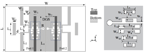
Figure 1: Configuration of the compact wideband filtering antenna. L 8, L 12.5, L 4.2, L 22, L 3.2, L 1.6, L 4.2, L 2, L 3, L 1.5, W 2, W 2, W 0.65, W 4, W 2, W 2, W 6, W 0.3 mm, W 1 mm, W 1.1, W 0.5, W 0.2, R 0.8, and d 3 (unit: mm).
A. Single filtering antenna with wideband high F/B characteristics
The evolution process of the filtering slot antenna with wideband high F/B characteristics is depicted in Fig. 2 and the corresponding reflection coefficients and F/B ratio are shown in Fig. 3. The basic structure of the single antenna is a modified defective ground slot antenna [12], which exhibits good filtering characteristics in the frequency domain, as seen in Fig. 3 (a). Figure 3 (b) demonstrates the F/B ratio curve of the unmodified Ant.(a) slot antenna. It can be observed from Fig. 3 (b) that Ant.(a) shows a high F/B ratio in the frequency range of 8-10 GHz, whereas the F/B ratio is lower in the 3-7 GHz frequency range. To obtain better directivity of the filter slot antenna in a wide band, a passive terminal and a pair of rectangular slots are introduced on the Ant.(a), named Ant.(b) and Ant.(c), as illustrated in Figs. 2 (b) and (c), respectively. It can be seen from Fig. 3 (b) that Ant.(b), which introduces passive termination, achieves a significant improvement in the ratio of F/B at 8-11 GHz, compared to Ant.(a). Ant.(c), which introduces a pair of rectangular slots, achieves an overall improvement in the ratio of F/B at 2-12 GHz compared to the previous two antennas, and the ratio of F/B is more than 15 dB. In addition, the introduction of slots on both sides of the Ant.(c) does not have a negative impact on the sideband selection characteristics and in-band impedance of the slot antenna, as shown in Fig. 3 (a).
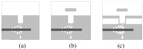
Figure 2: Evolution of the single filtering antenna with wideband high F/B characteristics.
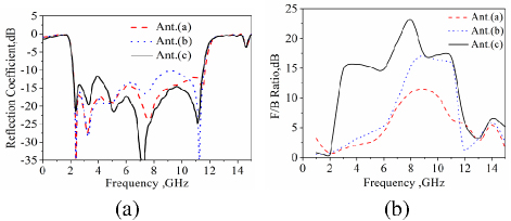
Figure 3: (a) Reflection coefficients and (b) F/B ratio of the single filtering antenna in Fig. 2.
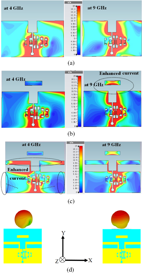
Figure 4: Current distributions (a), (b), (c) at 4 GHz and 9 GHz of the slot antenna Ant.(a), Ant.(b), and Ant.(c) in Fig. 2. Main vibrator (d), (e) at 4 GHz and 9 GHz of the slot antenna Ant.(c).
Figure 4 (a) gives the current distribution of Ant.(a) at a low frequency of 4 GHz and a high frequency of 9 GHz before the improvement. It can be seen from Fig. 4 (b) that, compared to low frequency, the lead terminal has a more obvious influence on the current distribution of high frequency. The current distribution of the slot antenna near the lead terminal and in the direction of the opening is significantly enhanced. To further enhance the F/B ratio and directivity of the filtering slot antenna at low frequencies (3-7 GHz), a pair of rectangular slots are etched on both sides of the slot antenna as seen in Fig. 2 (c). It is observed from Fig. 4 (c) that well-designed rectangular slots can reduce the distribution of low-frequency current on both sides of the slot antenna and enhance the current intensity of the slot antenna at the low-frequency band along the X-direction, thus increasing the distribution of low-frequency current on the main vibrator.
In this paper, there are many parameters: we take d and L as examples. The specific parameters are analyzed as follows. The length of the active array of the slit antenna is L, the length of the passive array is L, and the distance between the passive terminals and the active array is d. In order to form a strong directivity, the lead antenna oscillator spacing should not be too large, and it is generally d/0.4. The effects of the distance between the arrays and the length of the oscillators on the F/B ratio are shown in Fig. 5.
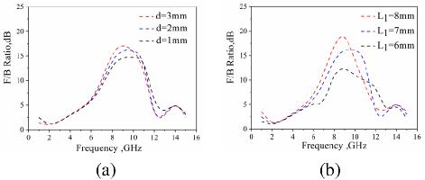
Figure 5: Effects of the distance between the arrays and the length of the oscillator on F/B ratio (a) d and (b) L
Figure 6 shows the changes in the E-plane and H-plane of the normalized pattern before and after the improvement of the slot antenna at low and high frequencies. It can be seen from Fig. 5 (a) that the passive terminal has little effect on the radiation pattern at low frequency (4 GHz), but it has a more obvious effect on the radiation pattern at high frequency (9 GHz). After adding the passive terminal, the back lobe of the slot antenna in the high-frequency pattern is reduced, and the maximum F/B ratio of the pattern is more than 15 dB, as shown in Fig. 5 (b). This further shows that the passive terminal can enhance the directivity of the slot antenna at high frequencies and has the function of guiding electromagnetic waves to propagate in a certaindirection.
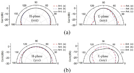
Figure 6: Effects of the passive terminal and rectangular slots on radiation pattern at (a) 4 GHz and at (b)9 GHz.
B. 22 MIMO antenna designed using directional filtering slot antenna as the element
In this design, two modified directional slot antennas are placed back-to-back, and the directivity of the directional slot antennas is used to achieve pattern diversity. Good isolation between MIMO antenna units can be achieved without using complex decoupling structures, as seen in Fig. 1. Figure 7 shows the simulated reflection coefficient and isolation of the UWB slot MIMO antenna. It can be seen from Fig. 7 (a) that the working bandwidth of the slot MIMO antenna is 2.8-11.2 GHz, which meets the application range of UWB. At the same time, due to the good filtering characteristics of the antenna unit, it shows obvious advantages in out-of-band harmonic suppression and coupling suppression. Furthermore, the MIMO slot antenna has high isolation (S20 dB) in the working frequency band without adding any decoupling structures. To further prove the element antenna orientation characteristics and wide F/B ratio have a significant effect on coupling suppression, Figs. 3, 6, and 7 (b) show the relationship among the F/B ratio, antenna orientation characteristics, and isolation S of the MIMO antenna. It can be seen from Fig. 7 (b) that Ant.(c) has the greatest the F/B ratio, the strongest direction, and the best isolation between the two unit antennas.
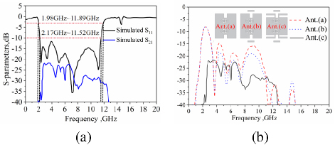
Figure 7: (a) Simulated S-parameters of the proposed MIMO slot antenna and (b) simulated transmission coefficient of antenna Ant.(a), Ant.(b) and Ant.(c) placed back-to-back.
To better illustrate the effect on coupling between the MIMO slot antennas after adding lead terminals and slots, Fig. 8 shows the current distributions of the UWB slot MIMO antenna at 3 GHz, 6 GHz, and 10 GHz, respectively. In the MIMO filtering slot antenna, one of the ports is excited and the other is terminated with a 50 load. It can be seen that when Port 1 adds incentives and Port 2 connection load, the current of each frequency point is mainly distributed in the upper half, and the lower part is small. Current distributions of the MIMO slot antenna are in agreement with the simulation S in Fig. 7. It is also proven that the MIMO slot antenna with a well-designed filtering directional element can enhance isolation of the proposeddesign.
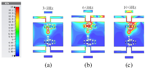
Figure 8: Current distribution of the UWB MIMO slot antenna in different frequency bands: (a) 3 GHz, (b) 6 GHz, and (c) 10 GHz.
III. RESULTS AND DISCUSSION
To further verify the effectiveness of the directional filtering slot antenna, the design was processed and measured. Figure 9 illustrates the measured and simulated results of the presented antenna. It can be seen in Fig. 8 (a) that the experimental reflection coefficient S is far below 10 dB within 2.8-11.3 GHz (120%), exhibiting desirable sideband selection property. In addition, clear out-of-band suppressions can be also found through the low band (0-2 GHz) and high band (13-20 GHz). Meanwhile, according to equation (1), the rectangularity coefficient K of the antenna has a simulated value of 1.059 and a measured value of 1.144, both of which are close to 1 (shown Figs. 9 (a) and 7). The above results show that the antenna has excellent band-edge selectivity and out-of-band rejection characteristics. The resonance point at 15 GHz is mainly caused by the coupling of the radiation slot and DGS and does not affect the performance of the antenna. As can be seen in Fig. 8 (b), the maximum gain of the antenna is 5.5 dBi, and efficiency is greater than 80% in the operating band. Furthermore, compared with references [2–5,11–14], the antenna shows better filtering performance.
| (1) |
Figure 10 shows the simulated and measured results of the F/B ratio of the antenna. It can be seen from Fig. 9 that the measured results of the F/B ratio agree well with the simulation results. In addition, the measured F/B ratio is greater than 15 dB in a wide bandwidth (114%), which means that the proposed design has outstanding directional characteristics.
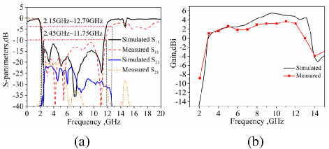
Figure 9: (a) Measured and simulated reflection coefficient and (b) measured and simulated gain.
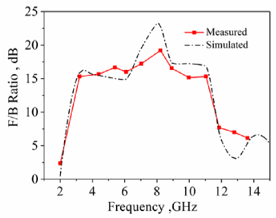
Figure 10: Measured and simulated F/B ratio of the antenna radiation pattern.
Figure 11 plots the simulated and measured far-field radiation patterns of the directional filtering slot UWB antenna in the E-plane (XOY-plane) and H-plane (YOZ-plane) at 3.0 GHz, 6 GHz, and 10 GHz, respectively. The cross-polarization radiation patterns at three points in the E-plane are also shown. From the radiation pattern, it can be observed that the experimental measurements are in good agreement with the simulation results, and the performance of the proposed design is acceptable over the operating frequency band. The plots also reveal the unidirectional radiation characteristics of the antenna. In addition, the cross-polarization level on the E-plane at 3 GHz, 6 GHz, and 10 GHz are less than20 dB.
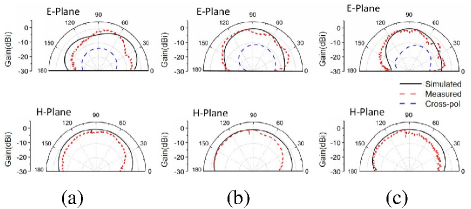
Figure 11: Measured radiation patterns at (a) 3.0 GHz, (b) 6 GHz, and (c) 10 GHz.
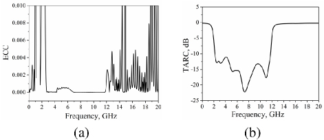
Figure 12: (a) ECC and (b) TARC of the MIMO slot antenna.
For a MIMO antenna, ECC is a parameter describing the degree of correlation between MIMO antenna channels and is an important indicator for judging whether the MIMO antenna can be applied in a MIMO system. Figure 12 (a) shows the ECC curve calculated by the two-unit MIMO slot antenna. It can be seen from Fig. 12 (a) that the ECC curve corresponds to its reflection coefficient. In the working frequency band, a lower ECC0.002 illustrates that the antenna has better diversity performance. At the same time, TARC is below 10 dB across the operating frequency band in the Fig. 12 (b), indicating that the designed MIMO antenna exhibits low reflection loss and excellent phase stability, which ensures reliable signal transmission.
In addition, due to the filtering characteristics of the antenna itself, the ECC curves calculated from the S-parameters show obvious differences between in-band and out-of-band, which further illustrates that with the improvement of antenna functionalization requirements in current wireless communication systems. The comprehensive performance of the two-unit MIMO filtering slot antenna in the performance has good competitiveness and application prospects in subsequent UWB system applications.
To highlight the novelty of the proposed design, a comparative study of some other competitive antennas is presented in Table 1. Merits of the proposed design can be observed: good bandwidth, band-edge selectivity, out-of-band suppression, and high F/B ratio across the UWB band. This means that the directional filtering slot antenna can suppress out-of-band interference in the frequency domain and interference from other directions in the space domain, which has obvious advantages compared to other broadbandantennas.
Table 1: Comparison with reported antennas
| Ref. | Size(mm) | BW(GHz) | Filtering Function | F/B (dB) | Radiation Band width F/B15 dB | |
| [2] | 3.5 | 8.9317.9 | 3.1-11 | No | 10 | - |
| [3] | 4.4 | 4032 | 3-11 | No | 10 | - |
| [4] | 3.55 | 7.520 | 3-20 | No | 10 | - |
| [5] | 2.2 | 2412 | 3.1-11 | Yes | 10 | - |
| [11] | 2.55 | 2215 | 3.8-11 | No | 10 | - |
| [12] | 3.48 | 5560 | 0.689 | No | 14 | - |
| [13] | 4.4 | 105135 | 1.68-3.97,2.4-4.09 | No | 10 | - |
| [14] | 3.3 | 8090 | 2.4-2.5,4.9-5.9 | No | 15 | 13% |
| This design | 2.2 | 2927 | 2.8-11.3(120%) | Yes | 15 | 114% |
IV. CONCLUSION
In this paper, a directional filtering slot antenna that boasts a wideband high F/B is proposed. Compared to conventional unit cell structures, our proposed antenna facilitates easy design with high-quality filtering and directional features. The unit element’s filtering and directional characteristics can be independently adjusted through the use of slot DGS and leading terminal, respectively. Measured results indicate a 10 dB reflection coefficient bandwidth of 2.8-11.3 GHz (120%), displaying significantly better sideband selection characteristics and effective out-of-band suppression. F/B remains above 15 dB with excellent directivity throughout the operational frequency. The simulations and experimental results of the MIMO antenna show good agreement, highlighting the proposed design as an outstanding option for portable UWB communication systems. Furthermore, the lower ECC (ECC0.002) in the wide working band underscores the antenna’s optimal diversity performance.
ACKNOWLEDGMENT
This work was supported in part by Natural Science Foundation of China for its support under Grant 62301428, 62201489, 62401465; in part by Natural Science Basic Research Program of Shanxi Province, China (2024JC-YBQN-0666), (2022JQ-699), (2023-J C-QN-0657), (2022JM-380), (2023-JC-QN-0500); in part by Xi’an Science and Technology Plan Project under Grant 2021JH-06-0038, 24GXFW0086; and in part by the Application Technology Research and Development Reserve Project of Beilin District, Xi’an under Grant GX2416.
REFERENCES
[1] D. Aissaoui, A. Chaabane, N. Boukli-Hacene, and T. A. Denidni, “Bandwidth enhancement of slot antenna using fractal shaped isosceles for UWB applications,” Applied Computational Electromagnetics Society (ACES) Journal, vol. 37, no. 9, pp. 977-985, Sep. 2022.
[2] A. Bekasiewicz and S. Koziel, “Structure and EM-driven design of novel compact UWB slot antenna,” IET Microw. Antennas Propag., vol. 11, no. 2, pp. 219-223, Jan. 2017.
[3] M. Gopikrishna, D. Das Krishna, C. K. Aanandan, P. Mohanan, and K. Vasudevan, “Design of a microstrip fed step slot antenna for UWB communication,” Microw. Opt. Technol. Lett., vol. 51, no. 4, pp. 1126-1129, Apr. 2009.
[4] A. A. R. Saad and H. A. Mohamed, “Bandwidth-enlargement of a low-profile open-ring slot antenna based on SIW structure,” IEEE Antennas Wireless Propag. Lett., vol. 16, pp. 2885-2888, Sep.2017.
[5] Y. Zhang and C. Li, “Design of small dual band-notched UWB slot antenna,” Electron. Lett., vol. 51, no. 22, pp. 1727-1728, Oct. 2015.
[6] Y. S. Li, W. X. Li, and W. H. Yu, “A switchable UWB slot antenna using SIS-HSIR and SIS-SIR for multi-mode wireless communications applications,” Applied Computational Electromagnetics Society (ACES) Journal, vol. 27, no. 4, pp. 340-351, May 2022.
[7] S. Bahrami, G. Moloudian, H. Song, and J. L. Buckley, “Reconfigurable UWB circularly polarized slot antenna with three modes of operation and continuous tuning rang,” IEEE Trans. Antennas Propag., vol. 70, no. 3, pp. 8542-8547, Nov.2022.
[8] G. Srivastava and A. Mohan, “Compact MIMO slot antenna for UWB applications,” IEEE Antennas Wireless Propag. Lett., vol. 15, pp. 1057-1060, 2016.
[9] G. Srivastava, A. Mohan, and A. Chakrabarty, “Compact reconfigurable UWB slot antenna for cognitive radio applications,” IEEE Antennas Wireless Propag. Lett., vol. 16, pp. 1139-1142,2017.
[10] H. Yang, X. Xi, Y. Zhao, L. Wang, and X. Shi, “Design of compact ultra-wideband slot antenna with improved band-edge selectivity,” IEEE Antennas Wireless Propag. Lett., vol. 17, no. 6, pp. 946-950, June 2018.
[11] C. Chen, “A compact wideband endfire filtering antenna inspired by a uniplanar microstrip antenna,” IEEE Antennas Wireless Propag. Lett., vol. 21, no. 4, pp. 853-857, Apr. 2022.
[12] H. Yang, X. Xi, Y. Zhao, Y. Tan, Y. Yuan, and L. Wang, “Compact slot antenna with enhanced band-edge selectivity and switchable band-notched functions for UWB applications,” IET Microw. Antennas & Propag., vol. 13, no. 7, pp. 982-990, June 2019.
[13] C. Wang and T. Sun, “Design of a microstrip monopole slot antenna with unidirectional radiation characteristics,” IEEE Trans. Antennas Propag., vol. 59, no. 4, pp. 1389-1393, Apr. 2011.
[14] Y. Xiao, Y. Qi, F. Li, J. Fan, W. Yu, and L. Lu, “Dual-band directional slot antenna for Wi-Fi application,” IEEE Trans. Antennas Propag., vol. 66, no. 8, pp. 4277-4281, Aug. 2018.
[15] H. Zhang, Y. Jiao, and Z. Weng, “A novel dual-wideband directional dipole antenna with double reflecting floors,” IEEE Antennas Wirel. Propag. Lett., vol. 16, pp. 1941-1944, Mar. 2017.
[16] R. George and T. A. J. Mary, “Review on directional antenna for wireless sensor network applications,” IET Communications, vol. 14, pp. 715-722, Mar. 2020.
BIOGRAPHIES

Hailong Yang received the B.S. in communicating engineering from Heze University, Heze, China, in 2012. M.S and Ph.D. degrees in communicating engineering from Xi’an University of Technology, Xi’an, China, in 2015 and 2019. His research interests include wave propagation and antenna design.

Haitian Liu was born in Liaoningi Province, China, 1999. He is currently pursuing a Master of Engineering degree in the School of Electronic Engineering, Xi’an University of Posts and Telecommunications. His current research interests include artificial intelligence, and array antennas.

Xuping Li was born in Xi’an, Shanxi, China, in 1981. He received the Ph.D. degree in electromagnetic fields and microwave technology from Xidian University, Xi’an, China, in 2015. His research interests are antenna theory and engineering.

Yapeng Li received the Ph.D. degree in electronic science and technology from Xidian University, Xi’an, China, in 2020. His research interests include phased array radar and antenna design.

Shanzhe Wang received the Ph.D. degree in Electronic Science and Technology from Beijing Jiaotong University, Beijing, China, in 2022. His research interests include fixed-frequency beam-scanning leaky-wave antennas.

Jinsheng Zhang received the Ph.D. degree in Control Science and Engineering from the Xi’an Research Institute of High-Tech, Xi’an, China, in 2009. He is currently a professor at the Department of Navigation, Guidance and Simulation.

Chenhao Wang received the Ph.D. degree in electromagnetic field and microwave technology from Xi’an University of Technology, Xi’an, China, in 2022. His current research interests include spoof surface plasmon polaritons.

Yun Fang received his Ph.D. degree in Electromagnetic Field and Microwave Technology in 2020. His research interests include numerical computation of electromagnetic field wave propagation.
ACES JOURNAL, Vol. 39, No. 11, 980–986
doi: 10.13052/2024.ACES.J.391106
© 2024 River Publishers