Zigzag Antenna Design Based on Machine Learning
Jae Youn Park and Jaeyul Choo
Department of Electronics Engineering
Andong National University, Andong 36729, Korea
qkrwo4553@gmail.com, jychoo@anu.ac.kr
Submitted On: May 17, 2024; Accepted On: January 14, 2025
ABSTRACT
In this paper, we propose the design of a zigzag antenna using machine learning (ML) techniques. We trained the deep neural network that was to be employed for the ML model using training data, after which we evaluated the maturity of the trained model using mean squared error and R-squared metrics. Next, we utilized random search in conjunction with the trained model to derive a design of the optimal zigzag antenna having good impedance matching characteristics. We then validated the applicability of the ML techniques in antenna design based on the agreement between measured and simulated reflection coefficients.
Index Terms: Deep neural network, machine learning technique, random search, zigzag antenna.
I. INTRODUCTION
Recently, the continued development of wireless communication systems has led to antennas being considered as some of the most important components in a wireless communication system [1]. In a wireless communication system, the antennas located at the endpoint in the system architecture play an important role in transmitting or receiving electromagnetic waves that include various types of information. When designing antennas for wireless communication, various characteristics are generally considered, including antenna size, impedance matching, radiation efficiency, radiating gain and pattern, and polarization in the frequency band of interest. Among the aforementioned characteristics of antennas, antenna size is often evaluated to be important because the size of the designed antenna determines the applicability to the wireless communication. Therefore, small antennas with antenna performance that satisfies the demands for the target application are generally preferred.
In attempts to reduce antenna size, studies have historically focused on the structure and material of antennas. The zigzag-shaped antenna (zigzag antenna) structure is representative to miniaturize antennas. The zigzag-shaped wire is effective for achieving a compact antenna design for use in constrained spaces due to the bent wire at specific angles across multiple positions [2]. The zigzag-shaped wire is also effective for achieving the desired antenna impedance by finely adjusting the pitch angle and the electrical length of each wire-subsection. This characteristic can facilitate good impedance matching in the desired frequency band. Moreover, the zigzag antenna offers the capability of having directional radiation characteristics in a target direction by modifying the arrangement of the wire-subsections [3]. It is therefore necessary to optimize antenna structure because the aforementioned characteristics of the zigzag antenna are dependent upon the shape of the zigzag wire [4–8].
To optimize the antenna structure, a genetic algorithm (GA) and a particle swarm optimization (PSO) technique have been employed in [4–6] and [7, 8], respectively. Even though both GA optimization and PSO provide globally optimum results, they have some limitations; for example, when using either method, it is necessary to verify the performance of sample antennas through numerical analysis. The computation time required for numerical analysis is an even more significant limitation in applying the optimization algorithm to antenna design. In response to these limitations of global optimization, we alternatively propose an antenna performance prediction technique that utilizes machine learning (ML) for time-efficient prediction of antenna performance. We also validate this proposed method for estimating antenna performance by comparing the antenna performance predicted by ML with the corresponding predictions of a commercial simulator. In the following, section II explains the process of developing an ML model for predicting antenna performance, while section III details the application of the trained ML model to structural optimization of the zigzag antenna.
II. MACHINE-LEARNING-BASED ANTENNA PERFORMANCE PREDICTION
The ML technique has recently been utilized in various types of applications, including electromagnetic applications. The applicability of ML techniques has been extended to antenna design, where they are used to substitute the numerical analysis based on Maxwell’s equations [9]. The ML algorithms that are typically applied in supervised learning include logistic regression (LR), support vector machine (SVM), decision tree (DT), random forest (RF), neural network (NN), and others [10]. Among them, NN is composed of three types of layers: an input layer for receiving multiple input data, an output layer that is responsible for the output of the data, and hidden layers having multiple nodes between the input and output layers. Moreover, NNs, which are designed to mimic the principles and structure of the human brain, can generally be categorized into artificial neural networks (ANN) and deep neural networks (DNN) depending on the number of hidden layers [11]. We have found many previous works showing that DNN models trained with multiple hidden layers achieve favorable prediction performance [12]. Inspired by these works, we herein designed an antenna with good impedance-matching characteristics by using ML based on the DNN structure. In the following, we explain how the ML process is composed of the generation and preprocessing of training data, derivation, and validation of ML model derivation.
A. Antenna structure
In this study, we used ML to design a zigzag antenna with high-quality impedance-matching characteristics in the frequency ranges from 950 to 1050 MHz and from 900 to 1100 MHz. Figure 1 illustrates the representative structure of this zigzag antenna. The zigzag antenna consists of five subsections (wire radius: 0.5 mm and material: copper) determined by the bending point P (x, z) in the plane (n ). To define the allowable electrical antenna size, as shown in Fig. 1, we set the zigzag antenna to exist in a hemisphere space as determined by kr of 2 on an infinite grounded plane, where k is the wave number at 1000 MHz and r is the radius of the sphere that encloses the entire antenna structure.
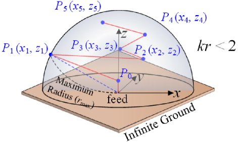
Figure 1: Structure of zigzag antenna with five bending points.
B. Generation and preprocessing of machine learning data
To create an ML model that estimates the performance of the proposed zigzag antenna, it is necessary to have sufficient training data corresponding to various antenna structures. In this study, we used training data that included information on the location of the bending points determining the antenna structure and the evaluation values (Cost) indicating antenna performance. To elaborate, we expressed the geometrical information of the n-th point (n ) on the proposed antenna as the location (x, y, z) in rectangular coordinates. To evaluate the performance of a sample antenna in the training process, we defined Cost as the average reflection loss in the frequency band of interest, as indicated by equation (1). In (1), the antenna impedance Z at the frequency f was derived using a Numerical Electromagnetic Code (NEC) simulation [13]:
| (1) |
Here, M, Z(f), and Z are defined as the total number of frequencies considered in the frequency bands of interest (950 to 1050 MHz for type 1 or 900 to 1100 MHz for type 2), the antenna impedance at the considered frequency f, and the characteristic impedance, respectively. In this paper, Z was set to 50 , and M was set to 101 and 201, resulting from the frequency increment of 1 MHz in 950 MHz ( f) to 1050 MHz ( f) and 900 MHz ( f) to 1100 MHz ( f), respectively.
C. Machine learning execution and machine learning model derivation
We used the training data that included geometrical and performance information derived from sample antennas 100,000 and 200,000 for the frequency bands of interest from 950 to 1050 MHz and from 900 to 1100 MHz, respectively. We also used 70%, 15%, and 15% of the collected training data as training data, validation data, and test data, respectively. We then applied the collected data to train the DNN model, as shown in Fig. 2. In Fig. 2, the employed DNN model consists of an input layer, hidden layers, and an output layer; the input layer receives information about the antenna structure whereas the hidden layers compute weighted sums from various input nodes and apply an activation function to pass this value to the next hidden layer or the output layer [14]. Finally, the output layer serves as the ultimate result, where the evaluation value (Cost) representing the performance of the antenna is the output.
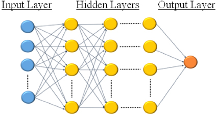
Figure 2: Structure of zigzag antenna with five bending points.
Table 1: Specifications of the applied DNN model
| LayerType | Number of Nodes | ActivationFunction | ||
| Type 1 | Type 2 | |||
| Input layer | 10 | - | ||
| Hidden layers | 1 | 500 | 250 | ReLU |
| 2 | 250 | 150 | ||
| 3 | 250 | 150 | ||
| 4 | 125 | 150 | ||
| 5 | 50 | 150 | ||
| 6 | 25 | 110 | ||
| 7 | - | 50 | ||
| 8 | - | 36 | ||
| Output layer | 1 | Linear |
Table 2: Validation of predictable capability of the trained DNN model
| Antenna (Ant.) No. | Location of (mm) | Location of (mm) | Predicted Cost | Error (%) | |||||||||
| ML | NEC | ||||||||||||
| Ant. 1 (type 1, ) | 9 | 15 | 21 | 6 | 52 | 7 | 20 | 26 | 51 | 76 | 0.301 | 0.3 | 0.09 |
| Ant. 2 (type 2, ) | 52 | 77 | 58 | 46 | 3 | 7 | 45 | 57 | 82 | 89 | 0.299 | 0.3 | 1.04 |
| Ant. 3 (type 1, ) | 3 | 52 | 77 | 46 | 21 | 13 | 32 | 51 | 67 | 89 | 0.401 | 0.4 | 0.23 |
| Ant. 4 (type 2, ) | 58 | 70 | 64 | 40 | 21 | 13 | 32 | 57 | 82 | 89 | 0.405 | 0.4 | 1.19 |
| Ant. 5 (type 1, ) | 21 | 34 | 3 | 70 | 28 | 20 | 26 | 32 | 57 | 82 | 0.503 | 0.5 | 0.65 |
| Ant. 6 (type 2, ) | 40 | 9 | 34 | 83 | 52 | 7 | 20 | 32 | 38 | 70 | 0.498 | 0.5 | 0.40 |
| Ant. 7 (type 1, ) | 83 | 64 | 9 | 46 | 28 | 26 | 32 | 70 | 76 | 89 | 0.601 | 0.6 | 0.03 |
| Ant. 8 (type 2, ) | 83 | 64 | 40 | 9 | 15 | 20 | 51 | 57 | 70 | 82 | 0.597 | 0.6 | 0.55 |
The DNN model used in this study is characterized in Table 1, which details the number of nodes and type of activation functions assigned to the input layer, hidden layers, and output layer. In Table 1, types 1 and 2 indicate the frequency bands of interest from 950 to 1050 MHz and from 900 to 1100 MHz, respectively. As presented in Table 1, we trained the DNN model using the adaptive moment (Adam) optimization technique with a batch size of 1024 and a learning rate of 0.0001. Further, to assess the maturity of the trained DNN model, we used the mean squared error (MSE) and R-squared (R), which are respectively defined in equations (2) and (3), as evaluation metrics. Based on equations (2) and (3), as the DNN model becomes increasingly mature, the MSE and R values approach 0 and 1, respectively, which indicates that the trained ML model can predict values closely resembling the actual ones [15].
| (2) |
| (3) |
Y is the kth observed value, is the corresponding predicted value for Y, is the mean of the observed values, and n is the number of observations.
D. Validation of the trained machine learning model
To verify if the trained ML model can accurately predict the target performance of a zigzag antenna, sample antennas with simulated Cost values of 0.3, 0.4, 0.5, and 0.6 were selected using commercial NEC simulation. The predicted Cost values of these selected antennas were then compared with their actual Cost values [10]. As can be seen in Table 2, the Cost predicted by the ML model exhibits a small error rate of approximately 1.2% when compared to the Cost derived from the NEC simulation. This result indicates that the trained ML model can be used effectively in predicting the impedance-matching characteristic of zigzag antennas.
III. DERIVATION AND VALIDATION OF OPTIMIZED ANTENNAS
To design zigzag antennas with excellent impedance-matching characteristics, the validated ML model was used in conjunction with a random search technique to derive antenna structures that achieve minimized Cost values [13]. Table 3 presents the geometrical information and Cost values of the optimal antennas obtained from a random search. When comparing the Cost predicted by the ML model to that obtained from commercial NEC simulations, it was found that the ML model provides relatively accurate predictions with an error rate under 1%. To practically validate the impedance matching characteristics of the optimal antenna as listed in Table 3, the zigzag antennas with the optimal design (Opt. Ants. 1 and 2) were fabricated on a finite ground plane of 250 mm250 mm using a copper wire with a thickness of 1 mm.
Table 3: Geometrical parameters and Cost of the optimal zigzag antennas
| Antenna (Ant.) No. | Location of (mm) | Location of (mm) | Predicted Cost | Error (%) | |||||||||
| ML | NEC | ||||||||||||
| Opt. Ant. 1 (type ) | 52 | 83 | 70 | 21 | 3 | 7 | 45 | 57 | 76 | 89 | 0.180 | 0.181 | 0.86 |
| Opt. Ant. 2 (type 2, ) | 55 | 74 | 70 | 24 | 18 | 10 | 46 | 53 | 80 | 92 | 0.255 | 0.255 | 0.07 |
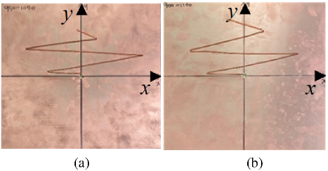
Figure 3: Image of the fabricated optimum zigzag antennas: (a) type 1 antenna and (b) type 2 antenna.
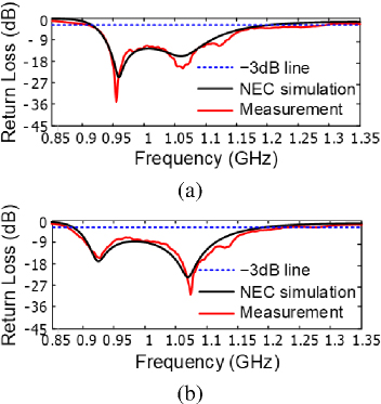
Figure 4: Impedance matching characteristics of the fabricated optimum zigzag antennas: (a) type 1 antenna and (b) type 2 antenna.
Figures 3 and 4 show images along with the measured and simulated reflection coefficients of the fabricated optimum zigzag antennas of the types 1 and 2, respectively. The measured 3 dB fractional bandwidths of the fabricated zigzag antennas for types 1 and 2 were, respectively, determined to be 37.5% from 911 to 1286 MHz and 29.4% from 887 to 1181 MHz at the operating frequency of 1 GHz. These measured results show favorable agreement with those from a commercial NEC simulation based on a method of moments, which were 27.7% from 916 to 1193 MHz and 29.4% from 887 to 1181 MHz, respectively. To interpret the operating principle of the fabricated antenna, we investigated the amplitude and phase of the induced current. From the investigated results, we found that the fabricated antenna works in a resonating mode at a lower resonance frequency and a traveling mode at a higher resonance frequency. Namely, it was found that the fabricated antenna works as multiple antennas of a monopole and dipoles in the resonating mode and operates as a traveling wave antenna having a broad matching bandwidth in the traveling mode [16].
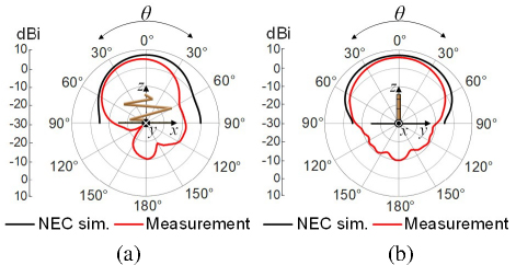
Figure 5: Total gain of the fabricated optimum antenna of type 1 on (a) plane () and (b) plane ().
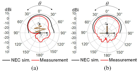
Figure 6: Total gain of the fabricated optimum antenna of type 2 on (a) plane () and (b) plane ().
In addition, we measured the radiation patterns of the fabricated antennas and compared with the simulated results, as shown in Figs. 5 and 6. In Figs. 5 and 6, the fabricated zigzag antennas of types 1 and 2 have maximum total gains of 5.93 dBi and 5.25 dBi in the direction of 0 at 1 GHz, respectively. When compared to the radiation patterns derived from NEC simulation under the assumption that the ground plane is extended infinitely, the overall radiation patterns were similar to the simulated radiation patterns except that the measured gains are overall lower than the simulated gains by 12 dB. We believe that the difference between the measured and simulated 3 dB matching bandwidths is caused by cable loss, the effect of finite ground, and fabrication and measurementerrors.
IV. CONCLUSION
In this paper, we designed a zigzag antenna with good impedance matching characteristics in the frequency ranges from 950 to 1050 MHz and from 900 to 1100 MHz using the ML technique. The ML model with DNN was trained using training data consisting of geometry and performance (Cost) information, where the performance information was derived from the evaluation of the average matching characteristic in the frequency band of interest. The maturity of the ML model was evaluated using MSE and R metrics, and the trained ML model was then validated by comparing the impedance-matching performance predicted by the trained ML model with those derived from commercial simulations.
Next, the validated ML model was used to derive an optimal structure of a zigzag antenna with the lowest Cost value (excellent impedance matching characteristics) through random search. Subsequently, the predicted Cost for the optimal antenna structure was compared with that calculated using a commercial simulator. Further, after fabricating the optimal zigzag antenna, we measured the reflection coefficients to revalidate the effectiveness of the proposed design method based on the ML technique. When comparing the measured reflection coefficients with those derived by the commercial simulator, we confirmed that both reflection coefficients show good agreement with each other. Consequently, we conclude that the antenna design method based on the ML technique can be effectively employed for optimal antenna design. The maturity of the ML model was evaluated using MSE and R metrics, and the trained ML model was then validated by comparing the impedance matching performance predicted by the trained ML model with those derived from commercial simulations.
Next, the validated ML model was used to derive an optimal structure of a zigzag antenna with the lowest Cost value (excellent impedance matching characteristics) through random search. Subsequently, the predicted Cost for the optimal antenna structure was compared with that calculated using a commercial simulator. Further, after fabricating the optimal zigzag antenna, we measured the reflection coefficients to revalidate the effectiveness of the proposed design method based on the ML technique. When comparing the measured reflection coefficients with those derived by the commercial simulator, we confirmed that both reflection coefficients show good agreement with each other. Consequently, we conclude that the antenna design method based on the ML technique can be effectively employed for optimal antenna design.
ACKNOWLEDGMENT
This work was supported in part by the Basic Science Research Program through the National Research Foundation of Korea (NRF) funded by the Ministry of Education (No. 2021R1I1A3050649), and in part by the Nuclear Safety Research Program through the Korea Foundation Of Nuclear Safety (KoFONS) using the financial resource granted by the Nuclear Safety and Security Commission (NSSC) of the Republic of Korea. (No.2106005).
REFERENCES
[1] Y. Lee, J. Ho, and I. Park, “Folded multi-strip monopole antenna,” J. Korean Inst. Electromagn. Eng. Sci., vol. 14, no. 11, pp. 1127-1133, Nov. 2003.
[2] S. K. Sharma and L. Shafai, “Investigations on miniaturized endfire vertically polarized quasi-fractal log-periodic zigzag antenna,” IEEE Trans Antennas Propag., vol. 52, no. 8, pp. 1957-1962, Aug. 2004.
[3] S. Zhao, C. Fumeaux, and C. Coleman, “Evolutionary optimization of zig-zag antennas using Gaussian and multiquadric radial basis functions,” in Proc. Asia-Pacific Microwave Conf., pp. 1594-1597, Dec. 2011.
[4] H. Choo, R. L. Rogers, and H. Ling, “Design of electrically small wire antennas using a pareto genetic algorithm,” IEEE Trans. Antennas Propag., vol. 53, no. 3, pp. 1038-1046, Mar. 2005.
[5] C. M. de J. van Coevorden, A. R. Bretones, M. F. Pantoja, S. G. Garcia, and A. Monorchio, “A new implementation of the hybrid Taguchi GA: Application to the design of a miniaturized log-periodic thin-wire antenna,” Applied Computational Electromagnetics Society (ACES) Journal, vol. 24, no. 1, pp. 21-31, Feb. 2009.
[6] X. Zhang, Y. Hu, and A. Zhan, “Design of a new balanced side slotted Vivaldi antenna with director using genetic algorithm,” Applied Computational Electromagnetics Society (ACES) Journal, vol. 38, no. 11, pp. 886-894, Nov. 2023.
[7] J. Robinson and Y. Rahmat-Samii, “Particle swarm optimization in electromagnetics,” IEEE Trans. Antennas Propag., vol. 52, no. 2, pp. 397-407, Feb. 2004.
[8] W. C. Weng, “Optimal design of an ultra-wideband antenna with the irregular shape on radiator using particle swarm optimization,” Applied Computational Electromagnetics Society (ACES) Journal, vol. 27, no. 5, pp. 427-434, May 2012.
[9] M. M. Khan, S. Hossain, P. Mozumdar, S. Akter, and R. H. Ashique, “A review on machine learning and deep learning for various antenna design applications,” Heliyon, vol. 8, no. 4, Apr. 2022.
[10] O. I. Abiodun, A. Jantan, A. E. Omolara, K. V. Dada, N. A. Mohamed, and H. Arshad, “State-of-the-art inartificial neural network applications: A survey,” Heliyon, vol. 4, no. 4, Nov.2018.
[11] K. M. Hamdia, X. Zhuang, and T. Rabczuk, “An efficient optimization approach for designing machine learning models based on genetic algorithm,” Neural Comput. Appl., vol. 33, pp. 1923-1933, June 2020.
[12] V. Anjitha and S. Kumar, “Optimal design of zig-zag antenna using nonlinear segment length and pitch angle,” Proc. Technol., vol. 6, pp. 799-805, Jan. 2012.
[13] S. Hu and Y. Zuo, “A review about building hidden layer methods of deep learning,” J. Adv. Info. Technol., vol. 7, no. 1, pp. 13-22, Feb. 2016.
[14] D. Chicco, M. J. Warrens, and G. Jurman, “The coefficient of determination R-squared is more informative than SMAPE, MAE, MAPE, MSE and RMSE in regression analysis evaluation,” Peer J. Comput. Sci., vol. 7, July 2021.
[15] P. Liashchynskyi and P. Liashchynskyi, “Grid search, random search, genetic algorithm: A big comparison for NAS,” arXiv:1912.06059, Dec. 2019.
[16] C. H. Walter, Traveling Wave Antennas. New York: McGraw-Hill, 1965.
BIOGRAPHIES

Jae Youn Park received the B.S. degree in Electrical Engineering from Andong National University, Andong, Korea, in 2024. He is currently working toward the master’s degree at Andong National University. His main interests are antenna theory and technology.

Jaeyul Choo received the B.S. and M.S. degrees in electronic and electrical engineering from Hongik University, Seoul, Korea, in 2004 and 2006, respectively, and the Ph.D. degree in electrical engineering from Korea Advanced Institute of Science and Technology (KAIST), Daejeon, Korea, in 2014. He was an Associate Research Engineer with the Central Research and Development Center, LS Electronic Company, Ltd., Anyang, Korea, from 2006 to 2010. He was a Senior Researcher at the Korea Institute of Nuclear Safety (KINS), Daejeon, Korea, from 2014 to 2020. In September 2020, he joined the department of electronics engineering, Andong National University, Andong, Korea, where he is currently an associate professor. His research interests include the design of tag and reader antennas for RFID, the electrical analysis for flip-chip bonding package, and the electromagnetic field analyses of vias, transmission lines, and scattering structure for dealing with electromagnetic interference problems.
ACES JOURNAL, Vol. 40, No. 1, 20–25
doi: 10.13052/2025.ACES.J.400103
© 2025 River Publishers