A Transparent Ultra-wideband Antenna Fed by CPW Based on Characteristic Mode Theory
Wanying Ren, Zhonggen Wang, Wenyan Nie, Weidong Mu, Chenlu Li,
and Mingqing Wang
1School of Electrical and Information Engineering
Anhui University of Science and Technology, Huainan 232001, China
wyren@aust.edu.cn,zgwang@ahu.edu.cn, mqwang@aust.edu.cn
2School of Mechanical and Electrical Engineering
Huainan Normal University, Huainan 232001, China
wynie5240@163.com
3School of Electronic and Information Engineering
Nanjing University of Aeronautics and Astronautics, Nanjing 211106, China
muweidong@nuaa.edu.cn
4School of Electrical and Information Engineering
Hefei Normal University, Hefei 230061, China
chenluli@hfnu.edu.cn
Submitted On: November 16, 2023; Accepted On: April 30, 2024
ABSTRACT
This paper proposes a high isolation transparent ultra-wideband (UWB) multiple-input multiple-output (MIMO) antenna based on characteristic mode theory. The antenna consists of four coplanar waveguide (CPW)-fed UWB monopoles, each of which is hollowed out into a mesh structure guided by feature mode theory with metal and substrates, with an excitation added at the feed point to successfully excite modes 1, 3, 5, and 7. These excited modes cover a frequency range of 1.7-13 GHz. An orthogonal layout is adopted to make the antenna structure more compact. Ultimately, a transparency of 76.3% and a radiation efficiency of over 85% are achieved, with an effective frequency band coverage of 1.32-12.15 GHz. A fan-shaped metal mesh (MM) decoupling structure is printed on the mesh structure of the antenna substrate, achieving isolation greater than 20 dB between any two components without reducing the antenna’s transparency. Across the entire operating frequency band, the gain of the antenna varies from 1.3 to 5.5 dBi within the effective bandwidth, and the envelope correlation coefficient (ECC) is less than 0.001. Additionally, the antenna exhibits good radiation characteristics. It can be easily manufactured at a low cost using traditional printed circuit board (PCB) and laser cutting techniques.
Index Terms: Characteristic mode, coplanar waveguide, multiple-input multiple-output, transparent antenna, ultra-wideband.
I. INTRODUCTION
The integration of ultra-wideband (UWB) and multiple-input multiple-output (MIMO) antenna technologies enables the development of wireless communication systems that can transmit data at higher speeds and with enhanced reliability. This allows for increased transmission range without increasing the radiation power of the antenna, while also addressing the multi-path fading problem [1]. Characteristic mode (CM) theory can analyze the radiation mechanism of the antenna from a physical perspective, providing effective guidance for antenna design. It can study the mode characteristics of the antenna without excitation, select suitable CMs for analysis [2, 3], and stimulate the required CMs using appropriate feeding methods to achieve the desired performance. A slotted broadband antenna is proposed in [2], analyzing six modes and ultimately achieving an impedance matching bandwidth of 2-3.7 GHz below 10 dB. A design consisting of two elliptical monopole UWB antennas is introduced in [3], which can excite several CMs, obtaining a bandwidth of 2.97-13.8 GHz. The ground plane’s cross-shaped shorting stub provides isolation greater than 15 dB.
To meet rising aesthetic standards, transparent antennas (TAs) overcome the shortcomings of traditional antennas with their unique “invisible” effect, enabling a more harmonious integration into the environment and facilitating agile deployment of outdoor street-level stations [4, 5]. Most TAs are classified into two categories: transparent conductive film (TCF) [6] and metal mesh (MM) [7]. Although TCFs are known for being highly transparent to light, they often suffer from significant ohmic losses [8], as evidenced by the gain of most TCF antennas being below 3 dB and efficiencies below 30%. The deposition of metal nanolayers onto TCFs can enhance the efficiency of TCF antennas, but this inevitably sacrifices transparency [9, 10].
MM antennas are categorized into two types: micro-MM films and wired MM [11]. Micro-MM films exhibit better conductivity and have optical transparency similar to TCFs. However, their manufacturing requires complex and expensive micro-nano fabrication techniques, such as inkjet printing. In contrast, wired MMs, while having poorer transparency due to relatively thick metal lines that block some light, can achieve over 70% transparency through careful design of the mesh pattern [12]. Moreover, wired MM antennas feature thicker conductors, resulting in lower resistance, and their efficiency can rival that of non-transparent metal antennas. Wired MM antennas can be manufactured using simple methods (such as printed circuit board [PCB] technology) and lower-cost materials [13]. Thus, when transparency requirements are not stringent, wired MM antennas are a preferable option [14, 15].
The metal UWB-MIMO antennas are coupled to one another through the process of near-field radiation, leading to inter-element coupling in the antenna elements. To address this, various decoupling methods have been proposed. High isolation in UWB-MIMO systems is achieved using trapezoidal structures in [16], serpentine lines in [17], open-loop annular resonators in [18], herringbone decoupling structures and I-slot in [19] and using orthogonal modes in [20]. To meet the requirements, there is an urgent need to develop a transparent antenna. In recent years, several transparent MIMO antenna designs based on TCF [21, 22] and micro-micro-miniaturized (micro-MM) [23] have been developed. Nevertheless, to the best of our knowledge, a UWB-MIMO TA based on CM theory with wired micro-miniaturized has not been reported.
This paper proposes a high-isolation UWB wired MM MIMO TA with an effective frequency range of 1.32-12.15 GHz. Guided by CM theory, we achieve 76.3% transparency and over 85% radiation efficiency by eliminating metal and substrate. The antenna substrate grid printing of a fan-shaped decoupling structure enables greater than 20 dB isolation between MIMO elements while maintaining transparency. Compared with existing transparent MIMO antennas, this design offers a wider bandwidth, lower coupling, higher efficiency, greater gain, and acceptable transparency. In addition, it performs well in radiation and diversity. This antenna can be manufactured at low cost using classical PCB and laser cutting techniques.
II. ANTENNA DESIGN
A. Antenna model
The geometric shape of the transparent antenna is illustrated in Fig. 1. The antenna is printed on an FR4 dielectric substrate with dimensions of 64 mm 64 mm 0.8 mm. The substrate has a relative dielectric constant of 4.4 and a loss tangent of 0.02. Each antenna unit comprises a hollow circular and rectangular radiation patch. The antenna elements are arranged orthogonally to enhance isolation and compactness. Furthermore, a fan-shaped metal isolation structure is strategically placed in the central area of the bottom plate to effectively minimize coupling between antennas. The orange component represents a metal radiation patch fed by a coplanar waveguide (CPW) transmission line. The manufacturing process follows the conventional method of PCB circuits. Initially, metal wires are printed onto opaque FR4 substrates using standard PCB technology, followed by hollow substrate cutting using laser technology. This method is simple and cost-effective. Parameter values for manufacturing the antenna are listed in Table 1, achieving a transparency of 76.3%.
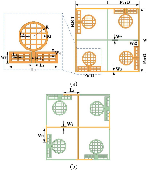
Figure 1: Geometrical structure of the proposed four-port transparent antenna: (a) front structure and (b) back structure.
B. Single UWB element design
Table 1: Dimensions of the proposed transparentantenna
| Parameter | L | L | L | L | L | L |
| Value (mm) | 64 | 23.5 | 1.3 | 0.34 | 0.5 | 0.5 |
| Parameter | L | R | R | W | W | W |
| Value (mm) | 16.5 | 7.2 | 6.2 | 64 | 6 | 1 |
| Parameter | W | W | W | W | W | |
| Value (mm) | 1 | 1 | 5.5 | 1 | 14 |
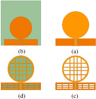
Figure 2: Current distribution corresponding to transparent processing steps of a single antenna unit: (a) initial, (b) step 1, (c) step 2, and (d) transparent.
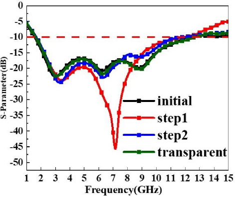
Figure 3: Reflection coefficient corresponding to the single antenna unit transparency processing step.
Modal significance (MS) is a crucial parameter in CMs, representing the normalized amplitude of the current mode. It is a key factor in measuring the degree of coupling between each mode and the external excitation source, as well as determining the radiation performance of the mode. Modes with MS values higher than 0.707 are deemed significant and essential for the antenna’s radiation. By analyzing the antenna’s MS curve, the radiation performance of each mode can be evaluated. The progression of a single antenna is illustrated in Fig. 2, with the corresponding simulated S-parameter curves presented in Fig. 3. CM theory indicates that the resonance characteristics of an antenna depend solely on the intrinsic properties of the antenna’s structure, materials, and size parameters, and are independent of external conditions such as the feeding method, position, and applied excitation source. The original UWB element is shown in Fig. 2 (a), where the green part is a 0.8 mm thick FR4 dielectric substrate. The antenna comprises a circular and a rectangular radiation patch, designed to ensure a smooth transition from the feedline, which improves impedance matching and enhances radiation efficiency. According to the initial curve in Fig. 3, the antenna exhibits broadband characteristics. The mode weighting coefficients (MWC) are a set of parameters used to describe the relative importance of different modes in the radiation or reception process of an antenna. By examining the peak positions of the MWC curve, one can identify the mode weights of the antenna at specific frequencies, which can then be used to excite the corresponding modes. A higher peak indicates a more significant contribution of that mode.
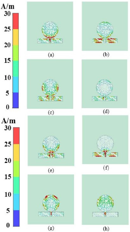
Figure 4: Mode current distribution of the initial structure; (a) mode 1 (2.57 GHz), (b) mode 2 (4.33 GHz), (c) mode 3 (12.48 GHz), (d) mode 4 (6.82 GHz), (e) mode 5 (8.01 GHz), (f) mode 6 (12.74 GHz), (g) mode 7 (10.67 GHz), and (h) mode 8 (12.74 GHz).
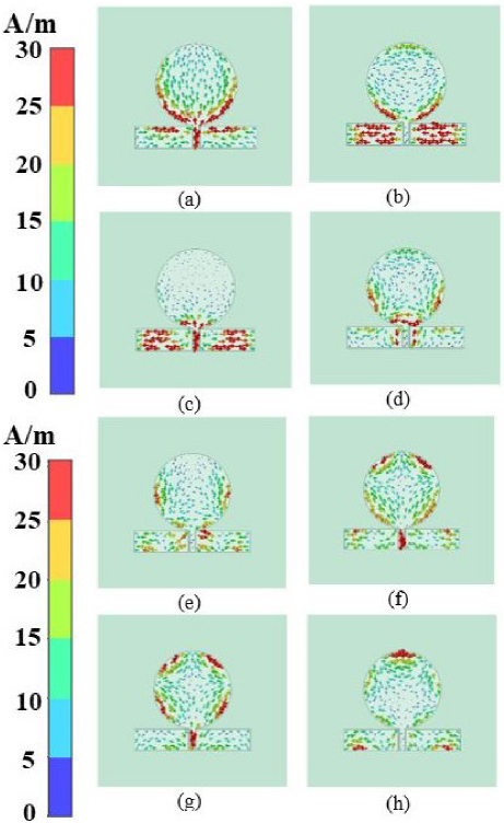
Figure 5: Mode current distribution of the step 1 structure; (a) mode 1 (2.42 GHz), (b) mode 2 (4.05 GHz), (c) mode 3 (9.15 GHz), (d) mode 4 (7.79 GHz), (e) mode 5 (6.57 GHz), (f) mode 6 (10.53 GHz), (g) mode 7 (12.03 GHz), and (h) mode 8 (12 GHz).
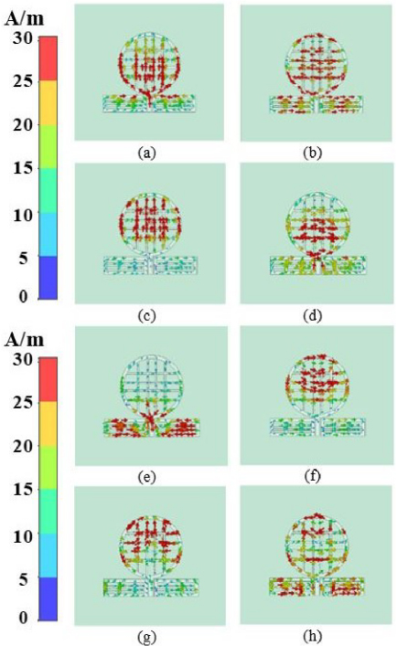
Figure 6: Mode current distribution of the step 2 structure; (a) mode 1 (2.30 GHz), (b) mode 2 (4.08 GHz), (c) mode 3 (6.48 GHz), (d) mode 4 (6.13 GHz), (e) mode 5 (6.75 GHz), (f) mode 6 (7.4 GHz), (g) mode 7 (10.17 GHz), and (h) mode 8 (11.01 GHz).
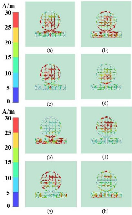
Figure 7: Mode current distribution of the transparent structure: (a) mode 1 (2.20 GHz), (b) mode 2 (3.93 GHz), (c) mode 3 (6.06 GHz), (d) mode 4 (6.17 GHz), (e) mode 5 (6.55 GHz), (f) mode 6 (7.37 GHz), (g) mode 7 (10.79 GHz), and (h) mode 8 (9.95 GHz).
CM analysis of the initial design in CST software is shown in Fig. 4, along with the resonant point mode current distribution. It can be observed that the currents of modes 1 and 6 flow towards the feed port, while the currents of modes 7 and 8 move along the x-axis towards the feed port. The currents at the feed port for modes 1, 6, 7, and 8 are relatively dense, indicating stronger current presence. Adding an excitation at the feed line can simultaneously activate these four modes. However, the currents of modes 2, 3, 4, and 5 are weak near the feed port, making it difficult to excite these modes with the excitation source. According to the MS curve in Fig. 8 (a), the four excited modes are unable to fully cover the required UWB frequency band. Therefore, additional significant modes need to be excited to meet performance requirements. The currents of each mode are primarily distributed around the center conductor of the CPW and the edges of the circular and rectangular patches. Since the currents in the middle of the rectangle and circle are weaker, the element can be hollowed out to resemble a grid without altering its radiation characteristics, thereby rendering it transparent. The antenna unit is optimized in three steps accordingly.
First, as illustrated in Fig. 2 (b), removing the substrate outside the coverage area of the metal patch antenna is necessary. Figure 5 shows the resonant mode current distribution of step 1 in CST software. The current distribution on the patch surface remains largely unchanged; therefore, removing the substrate has little effect on the CM. The currents of mode 1, mode 3, mode 6, and mode 7 are relatively strong at the feeding point. According to the MS curve in Fig. 8 (b), mode 4 and mode 5 have MS values greater than 0.9 in the frequency range above 6 GHz. The excited mode 1 and mode 3 can fully cover the 1.7-13 GHz frequency band, meeting the requirements of UWB antennas.
Second, as shown in Fig. 2 (c), the middle parts of the circular and rectangular metal patches are excavated into a grid pattern. It is noteworthy that the metal line widths of the grids in the middle of the rectangular and circular patches are set to 0.5 mm due to weaker currents, while the metal line widths at the edges of the patches are set to 1 mm to ensure low resistance during high current flow. Figure 6 shows the resonant mode current distribution of step 2 in CST software. The current is relatively evenly distributed on the metal grid, and modes 1, 3, 5, and 7 can be excited, although the currents at the feeding points of modes 3 and 7 are relatively weakened. The surface current of mode 1 antenna flows from both ends of the rectangular patch towards the feeding line and towards the top of the circular patch. In contrast, the surface current of mode 8 antenna circulates counterclockwise, making it difficult to excite. According to the MS curve in Fig. 8 (c), the MS values of mode 1 are all greater than 0.9 in the 3.8-10.1 GHz frequency band, and the MS values of mode 5 are all greater than 0.9 in the frequency band above 6.1 GHz. The excited CMs can cover the 1.6-13 GHz frequency range.
Finally, as depicted in Fig. 2 (d), the substrate shape corresponding to the radiation patch is also etched into a grid pattern to maximize transparency. Figure 7 illustrates the characteristic patterns of the transparent structure under the CST software’s resonance point mode current distribution. It can be observed that modes 1, 3, 5, and 7 can all be excited. Hollowing out the antenna substrate improves the impedance matching performance of the antenna. As depicted in Fig. 8 (d), the MS curve reveals that these excited modes can cover the 1.7-13 GHz frequency band, meeting our required performance criteria.
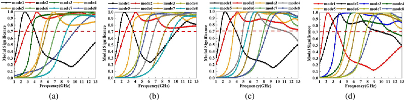
Figure 8: Modal significance of the transparent structure: (a) initial, (b) step 1, (c) step 2, and (d) transparent structure.
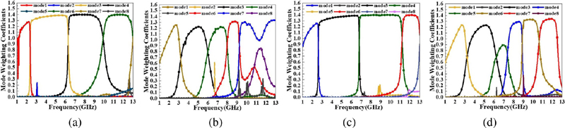
Figure 9: Mode weighting coefficients of the transparent structure: (a) initial, (b) step 1, (c) step 2, and (d) transparent structure.
According to the MWC curve shown in Fig. 9, it is observed that modes 1, 3, 4, and 7 have high weight coefficients in certain frequency bands, indicating that these modes have strong radiation or reception effects in those specific frequency ranges. Conversely, modes 2, 5, and 8 have relatively low weight coefficients across all frequency bands, suggesting that these modes have a minor impact on the overall performance of the antenna and are difficult to excite.
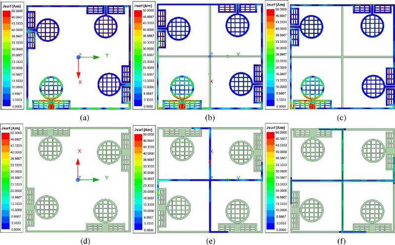
Figure 10: Developments in the design of decoupled structures for transparent antennas: (a)-(c) front structure of Ant1, Ant2, and Ant3; (d)-(f) back structure of Ant1, Ant2, and Ant3.
The reflection coefficients corresponding to each stage are shown in Fig. 7. The transparent UWB element of a single unit has a bandwidth of 1.7 to 12.6 GHz below 10 dB. Transparency can be defined as:
| (1) |
where S is the area of the meshed antenna’s metal portion and S is the total area of the solid shape’s metal surface before meshing. Therefore, the area of the hollowed-out portion is represented by S-S. According to calculations, the proposed single antenna has a transparency of 75.4%.
C. MIMO antenna design

Figure 11: Simulation of S parameters of three antenna structures: (a) S and (b) S and S.
The evolution of the antenna structure depicted in Fig. 10 illustrates the distribution of surface currents and provides further analysis on how the structural changes affect the antenna’s bandwidth and isolation. The S-parameters corresponding to each process are shown in Fig. 11. Antenna 1, as illustrated in Figs. 10 (a) and (d), consists of simple L-shaped substrates connected to each antenna unit, with MM coverage on the L-shaped substrate. When port 1 is excited, a significant amount of current couples to ports 2 and 4. The S12 and S13 curves in Fig. 11 (b) show that the isolation between adjacent and diagonal antenna units is largely below 20 dB. To mitigate coupling between antenna units, antenna 2, depicted in Figs. 10 (b) and (e), adds a cross-shaped dielectric substrate at the center of the antenna and prints a fan-shaped MM on the back of the substrate. The fan-shaped isolation structure reduces mutual interference and signal leakage by physically separating antenna elements and adjusting the electromagnetic field distribution, thereby enhancing the isolation and performance of the antenna system. The width of the fan-shaped metal wires matches the width of the substrate. When port 1 is excited, much of the current couples to the tail end of the fan-shaped structure, significantly reducing the current coupled to ports 2 and 4. Figure 11 (a) shows that the effective frequency range of antenna 2 is widened, and Fig. 11 (b) indicates that the coupling between adjacent antenna units exceeds 20 dB, while the isolation between diagonal antenna units remains slightly below 20 dB. To further enhance isolation between antenna units, a small rectangular branch is added at the turning point of the small fan-shaped MM, as shown in antenna 3 in Figs. 10 (c) and (f). The current uniformly couples to the small fan-shaped MM, with hardly any current visible on ports 2, 3, and 4. Figures 11 (a) and (b) demonstrate that this antenna achieves a better bandwidth of 1.32-12.15 GHz, with isolation exceeding 20 dB for both adjacent and diagonal positions. The final transparency of the antenna is 76.3% calculated using (1).
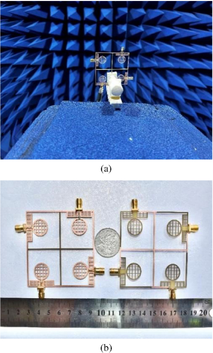
Figure 12: Proposed transparent antenna: (a) S-parameters measurement environment and (b) fabricated prototype.
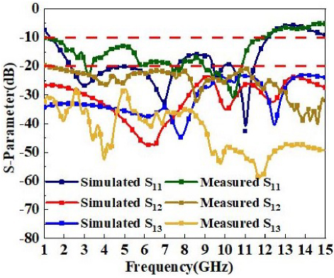
Figure 13: Simulated and measured S parameters of the proposed transparent MIMO antenna.
III. EXPERIMENTAL SIMULATION AND MEASUREMENT
A. S-parameters
The S-parameters of the transparent antenna were analyzed using the Agilent N5235A vector network analyzer. Figure 12 illustrates the S-parameter measurement environment and prototype. According to the S-parameter curves in Fig. 13, there is no significant deviation between the measured S11 result and the simulated result, and the antenna covers the desired bandwidth from 1.32 to 12.15 GHz. The results of the simulated and measured S and S tests are all below 20 dB across the entire working frequency band, indicating excellent isolation between MIMO elements. The results of the measurements are in good agreement with the results of the simulations. The discrepancies observed between the simulated and measured outcomes may be attributed to manufacturing imperfections or SMA connector and transmission line losses, which may result in minor frequency discrepancies.
B. Radiation properties
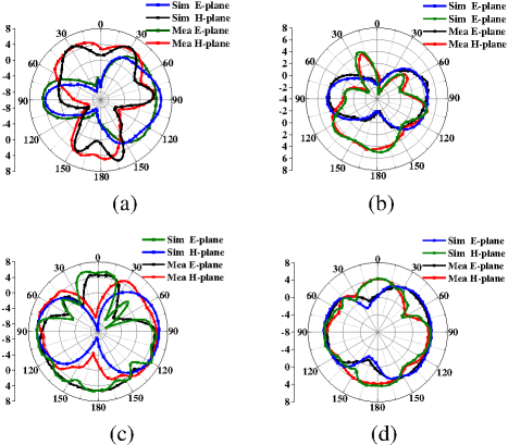
Figure 14: Simulated and measured radiation patterns at (a) 3 GHz, (b) 7 GHz, (b) 9.6 GHz, and (d) 11 GHz.
The 2-D radiation patterns of the E-plane and H-plane for port-1 of the transparent antenna were measured at 3 GHz, 7 GHz, 9.6 GHz, and 11 GHz, as illustrated in Fig. 14. At resonant frequencies of 3 GHz and 7 GHz, the E-plane exhibits excellent radiation characteristics at = 90 ( = 0). At 9.6 GHz, the E-plane exhibits almost omnidirectional radiation characteristics. At 11 GHz, the E-plane exhibits a digit ‘8’ shape with strong directional radiation at = 90 ( = 180). As previously stated, the distribution on the current antenna remains largely unaltered when it is transformed into a mesh structure.
The simulated and measured radiation efficiency and peak gain of the antenna across the operating frequency band are illustrated in Fig. 15. The radiation efficiency exceeds 85% over the entire operating frequency range, achieving a high efficiency of over 90% in the 5-12.3 GHz frequency band, while the peak gain of the antenna varies from 1.3 to 5.5 dBi. Despite the antenna being hollowed out, the narrowest metal line has a width of only 0.5 mm, resulting in a low resistance. Consequently, the efficiency and gain of this antenna are comparable to those of solid metal antennas and significantly superior to those of other types of transparentantennas.
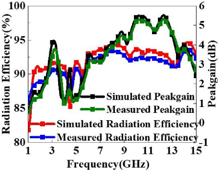
Figure 15: Simulated and measured radiation efficiency and peak gain of the proposed transparent MIMO antenna.
C. Diversity characteristics
The diversity performance indicators include envelope correlation coefficient (ECC), diversity gain (DG), total active reflection coefficient (TARC), and channel capacity loss (CCL). These indicators are essential metrics for evaluating the antenna’s capability to provide stable, high-quality, and diverse signal capabilities. These metrics are employed to ascertain whether the designed antenna meets the necessary specifications for wireless connection links operating within the UWBspectrum.
In the context of wireless communication links, the ECC is a critical parameter for determining channel isolation. According to regulatory requirements, MIMO antenna elements must maintain an ECC value of less than 0.5 to ensure optimal diversity performance. For multi-port MIMO antennas, the ECC is calculated as [24]:
| (2) |
where ECCrepresents the ECC between the i and j antenna elements. As illustrated in Fig. 16 (a), the ECC value of the transparent antenna is below 0.001 across the effective frequency band. The findings demonstrate that the radiation patterns of the antenna exhibit a high degree of independence, meaning that the antenna radiates independently with minimal interaction.
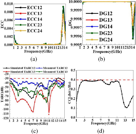
Figure 16: Diversity performance parameters of (a) ECC, (b) DG, (c) TARC, and (d) CCL.
DG is a metric used to evaluate the antenna’s ability to mitigate fading and enhance signal quality in multipath environments. It is a crucial performance indicator for UWB-MIMO antenna systems in combatting channel fading. The calculation formula for DG is as follows [25]:
| (3) |
The DG value of the transparent antenna, as shown in Fig. 16 (b), exceeds 9.9999 within the effective frequency band. This high DG value signifies that the antenna demonstrates excellent performance.
Table 2: Performance comparison of the proposed MIMO antenna with existing designs
| Ref. | Material | Transparency | Band | Isolation (dB) | Gain (dBi) | Efficiency | ECC |
| This work | FR4 and MM | 76.3% | 1.32-12.15 | 20 | 1.3 to 5.5 | 85% | 0.001 |
| [23] | Ni Embedded Micro MM | 93% | 4.4-5 | 20 | 3.8 | 85% | 0.005 |
| [29] | ITO and Ag | 88% | 2.5-10.6 | - | - | 66% | - |
| [30] | ITO and FTO | 72% | 2.4-11 | 20 | 2 to 2 | 60% | 0.04 |
| [31] | AgHT-4 | 70% | 2.2-6 | 15 | 0.5 | 41% | 0.016 |
| [33] | AgHT-8 | - | 3.1-10.6 | 15 | 6 to 2 | 10-20% | - |
The efficiency of a MIMO system is evaluated using a new metric called TARC, which measures the excessive coupling between antenna ports for any signal combination. The formula for calculating TARC in a MIMO system is expressed as [26]:
| (4) |
where TARC represents the TARC between the i and j antenna elements. Figure 16 (c) illustrates the TARC of the antenna, which is less than 30 dB within the effective frequency range. This low TARC value indicates minimal coupling effects in the MIMO system. The lower TARC ensures the independence of various channels in MIMO system transmitters and receivers, effectively utilizing multipath effects to enhance system capacity.
CCL represents the greatest quantity of data that can be transmitted successfully through a communication channel without incurring loss. This parameter is a crucial indicator for assessing the performance of MIMO antenna systems [27]. A low CCL value supports high data transmission rates. Specifically, a CCL value less than 0.5 bits/second/Hz indicates good data transmission quality, whereas a value exceeding 0.5 bits/second/Hz suggests lossy and poor data transmission. CCL can be calculated using the followingformulas [28]:
| (5) |
where:
| (6) |
| (7) | ||
| (8) |
and X indicates the correlation matrix of the receiving antenna. As illustrated in Fig. 16 (d), the CCL of this antenna is below 0.4 bits/second/Hz within the operating frequency range, thereby meeting therequirements.
D. Comparative study
Table 2 presents a detailed comparison of the proposed TA with several published antennas in terms of transparency, bandwidth, isolation, gain, efficiency, and ECC. Compared with [30, 31], our antenna exhibits higher transparency. Additionally, our bandwidth and gain are superior to those reported in [23, 29–32]. Furthermore, the proposed antenna demonstrates better efficiency and ECC than all other antennas. It also uses lower-cost materials and incorporates a unique decoupling structure. In addition, the proposed antenna exhibits superior radiation performance and diversity characteristics, making it highly suitable for indoor wireless communication.
IV. CONCLUSION
This paper presents a four-element UWB-MIMO transparent antenna designed based on CM theory. By observing the distribution of mode currents, individual antenna elements are hollowed out into a mesh pattern, with an excitation added at the feed point to successfully excite four out of eight significant modes simultaneously. These excited modes cover a frequency range of 1.7-13 GHz. Through simple branch connections and orthogonal placement in pairs, the antenna structure remains compact, printing a fan-shaped MM decoupling structure on the back of the branch connecting the antenna, resulting in a high-isolation antenna with isolation greater than 20 dB between antenna elements across the entire operating frequency band. This overcomes the drawbacks of most transparent antennas in terms of radiation characteristics, achieving 76.3% transparency and radiation efficiency exceeding 85%. It is fed by a CPW and covers an effective frequency range of 1.32-12.15 GHz. It maintains an ECC of less than 0.001 and achieves gains ranging from 1.3 to 5.5 dBi.
ACKNOWLEDGMENT
This work was supported in part by the Natural Science Research Project of Anhui Educational Committee under no. 2022AH051583 and no. 2022AH052138, and in part by the Anhui Province Graduate Academic Innovation Project under grant no. 2023xscx074.
REFERENCES
[1] K. Srivastava, S. Kumar, B. K. Kanaujia, and S. Dwari, “Design and packaging of ultra-wideband multiple-input-multiple-output/diversity antenna for wireless applications,” International Journal of RF and Microwave Computer-Aided Engineering, vol. 30, no. 10, July 2020.
[2] J. Zhao, Y. Chen, and S. Yang, “In-band radar cross-section reduction of slot antenna using characteristic modes,” IEEE Antennas and Wireless Propagation Letters, vol. 17, no. 7, pp. 1166-1170, July 2018.
[3] H. V. Singh and S. Tripathi, “Compact UWB MIMO antenna with cross-shaped unconnected ground stub using characteristic mode analysis,” Microwave and Optical Technology Letters, vol. 61, no. 7, pp. 1874-1881, July 2019.
[4] T. Peter, T. A. Rahman, S. W. Cheung, R. Nilavalan, H. F. Abutarboush, and A. Vilches, “A novel transparent UWB antenna for photovoltaic solar panel integration and RF energy harvesting,” IEEE Transactions on Antennas and Propagation, vol. 62, no. 4, pp. 1844-1853, Apr. 2014.
[5] Y. Yao, Y. Shao, J. Zhang, and J. Zhang, “Design of glass-integrated grid antenna using CMA for multiband indoor network,” in 2020 International Symposium on Antennas and Propagation (ISAP), pp. 481-482, Jan. 2021.
[6] D. Potti, Y. Tusharika, M. G. N. Alsath, S. Kirubaveni, M. Kanagasabai, and R. Sankararajan, “A novel optically transparent UWB antenna for automotive MIMO communications,” IEEE Transactions on Antennas and Propagation, vol. 69, no. 7, pp. 3821-3828, July 2021.
[7] Z. J. Silva, C. R. Valenta, and G. D. Durgin, “Optically transparent antennas: A survey of transparent microwave conductor performance and applications,” IEEE Antennas and Propagation Magazine, vol. 63, no. 1, pp. 27-39, Feb. 2021.
[8] R. B. Green, M. Guzman, N. Izyumskaya, B. Ullah, S. Hia, and J. Pitchford, “Optically transparent antennas and filters: A smart city concept to alleviate infrastructure and network capacity challenges,” IEEE Antennas and Propagation Magazine, vol. 61, no. 3, pp. 37-47, June2019.
[9] N. A. Eltresy, A. E. M. A. Elhamid, D. M. Elsheakh, H. M. Elhennawy, and E. A. Abdallah, “Silver sandwiched ITO based transparent antenna array for RF energy harvesting in 5G mid-range of frequencies,” IEEE Access, vol. 9, pp. 49476-49486, Mar. 2021.
[10] N. A. Eltresy, A. M. A. Elhamid, D. N. Elsheakh, E. A. Abdallah, and H. M. Elhennawy, “AgITO for high-performance semi-transparent wideband antenna applications,” Electronics. Letters, vol. 56, no. 15, pp. 749-750, July 2020.
[11] S. H. Kang and C. W. Jung, “Transparent patch antenna using metal mesh,” IEEE Transactions on Antennas and Propagation, vol. 66, no. 4, pp. 2095-2100, Apr. 2018.
[12] M. M. Rabie, H. El-Henawy, F. El-Hefnawy, and F. Ibrahim, “Meshed conductor and meshed substrate GPS L1 band microstrip antenna for CubeSat applications,” in 2018 35th National Radio Science Conference (NRSC), pp. 55-62, Mar. 2018.
[13] R. Yazdani, M. Yousefi, H. Aliakbarian, H. Oraizi, and G. A. E. Vandenbosch, “Miniaturized triple-band highly transparent antenna,” IEEE Transactions on Antennas and Propagation, vol. 68, no. 2, pp. 712-718, Feb. 2020.
[14] Y. Yao, B. Wu, Y. Shao, J. Zhang, and J. Zhang, “CPW-fed transparent antenna array using metal mesh,” in 2023 17th European Conference on Antennas and Propagation, pp. 1-5, Mar. 2023.
[15] T. Yekan and R. Baktur, “Conformal integrated solar panel antennas: Two effective integration methods of antennas with solar cells,” IEEE Antennas and Propagation Magazine, vol. 59, no. 2, pp. 69-78, Feb. 2017.
[16] Z. Tang, X. Wu, J. Zhan, S. Hu, Z. Xi, and Y. Liu, “Compact UWB-MIMO antenna with high isolation and triple band-notched characteristics,” IEEE Access, vol. 7, pp. 19856-19865, Feb. 2019.
[17] J. M. Lee, K. B. Kim, H. K. Ryu, and J. M. Woo, “A compact ultrawideband MIMO antenna with WLAN band-rejected operation for mobile devices,” IEEE Antennas and Wireless Propagation Letters, vol. 11, pp. 990-993, Aug. 2012.
[18] J. Huang, G. Dong, Q. Cai, Z. Chen, L. Li, and G. Liu, “Dual-band MIMO antenna for 5G/WLAN mobile terminals,” Micromachines, vol. 12, no. 489, pp. 1-12, Apr. 2021.
[19] Z. Lu, H. Lin, Z. Wang, W. Nie, and W. Mu, “Compact ACS-fed MIMO antenna with dual-band notch characteristics for UWB applications,” International Journal of Microwave and Wireless Technologies, pp. 1-9, Nov. 2023.
[20] R. Mathur and S. Dwari, “4-port extended ultrawideband MIMO/diversity antenna for indoor and outdoor wireless communication,” in 2023 IEEE Wireless Antenna and Microwave Symposium (WAMS), pp. 1-5, June 2023.
[21] A. Desai, M. Palandoken, J. Kulkarni, G. Byun, and T. K. Nguyen, “Wideband flexible/transparent connected-ground MIMO antennas for sub-6 GHz 5G and WLAN applications,” IEEE Access, vol. 9, pp. 147003-147015, Oct. 2021.
[22] G. Montisci, G. Mura, G. Muntoni, G. A. Casula, F. P. Chietera, and M. Aburish-Hmidat, “A curved microstrip patch antenna designed from transparent conductive films,” IEEE Access, vol. 11, pp. 839-848, Dec. 2023.
[23] H. C. Qiu, H. Liu, X. Jia, Z.-Y. Jiang, Y.-H. Liu, and J. Xu, “Compact, flexible, and transparent antennas based on embedded metallic mesh for wearable devices in 5G wireless network,” IEEE Transactions on Antennas and Propagation, vol. 69, no. 4, pp. 1864-1873, Apr. 2021.
[24] S. Blanch, J. Romeu, and I. Corbella, “Exact representation of antenna system diversity performance from input parameter description,” Electronics Letters, vol. 39, no. 9, pp. 705-707, May 2003.
[25] A. Iqbal, O. A. Saraereh, A. W. Ahmad, and S. Bashir, “Mutual coupling reduction using F-shaped stubs in UWB-MIMO antenna,” IEEE Access, vol. 6, pp. 2755-2759, Dec. 2018.
[26] R. N. Tiwari, P. Singh, B. K. Kanaujia, and K. Srivastava, “Neutralization technique based two and four port high isolation MIMO antennas for UWB communication,” International Journal of Electronics and Communications, vol. 110, no. 152828, Oct. 2019.
[27] S. S. Bhatia and N. Sharma, “Modified spokes wheel shaped MIMO antenna system for multiband and future 5G applications: Design and measurement,” Progress in Electromagnetics Research, vol. 117, pp. 261-276, 2021.
[28] I. Elfergani, A. Iqbal, C. Zebiri, A. Basir, J. Rodriguez, M. Sajedin, A. de O. Pereira, W. Mshwat, R. Abd-Alhameed, and S. Ullah, “Low profile and closely spaced four-element MIMO antenna for wireless body area networks,” Electronics, vol. 9, no. 2, p. 258, Feb. 2020.
[29] W. Kim, J. I. Oh, K. S. Kim, J. W. Yu, and K. J. Jung, “Efficiency-improved UWB transparent antennas using ITO/Ag/ITO multilayer electrode films,” IEEE Access, vol. 9, pp. 165385-165393, Nov. 2021.
[30] D. Potti, Y. Tusharika, M. G. N. Alsath, S Kirubavenit, M. Kanagasaba, and R. Sankararajan, “A novel optically transparent UWB antenna for automotive MIMO communications,” IEEE Transactions on Antennas and Propagation, vol. 69, no. 7, pp. 3821-3828, July 2021.
[31] A. Desai, M. Palandoken, J. Kulkarni, G. Byun, and T. K. Nguyen, “Wideband flexible/transparent connected-ground MIMO antennas for sub-6 GHz 5G and WLAN applications,” IEEE Access, vol. 9, pp. 147003-147015, Oct. 2021.
[32] T. Peter, R. Nilavalan, H. F. A. Tarboush, and S. W. Cheung, “A novel technique and soldering method to improve performance of transparent polymer antennas,” IEEE Antennas and Wireless Propagation Letters, vol. 9, pp. 918-921, Sep. 2010.
BIOGRAPHIES

Wanying Ren received the B.E. degree from Anhui University of Science and Technology in 2022. She is currently pursuing an M.S. degree at Anhui University of Science and Technology. Her current research interest includes the theory and design of MIMO antenna.

Zhonggen Wang received the Ph.D. degree in electromagnetic field and microwave technique from the Anhui University of China (AHU), Hefei, P. R. China, in 2014. Since 2014, he has been with the School of Electrical and Information Engineering, Anhui University of Science and Technology. His research interests include computational electromagnetics, array antennas, and reflect arrays.

Wenyan Nie is a professor at Huainan Normal University. She received the B.S. and M.S degrees from Anhui University of Science and Technology in 2007 and 2012, respectively. Her research interests include computational electromagnetic methods, antenna theory and design.

Weidong Mu received the M.S. degree from Anhui University of Science and Technology in 2023, and he is currently pursuing the Ph.D. degree in Nanjing University of Aeronautics and Astronautics (NUAA). His research interests include RCS reduction of antennas and MIMO-antenna decoupling.

Chenlu Li received the Ph.D. degree from Anhui University in 2017. She is currently working at Hefei Normal University. Her research interests electromagnetic scattering analysis of targets and filtering antenna design.

Mingqing Wang received the B.E. degree from Anhui University of Science and Technology in 2021. He received an M.S. degree at Anhui University of Science and Technology in 2024. His research interests include the antenna design based on the characteristic mode theory.
ACES JOURNAL, Vol. 39, No. 11, 987–998
doi: 10.13052/2024.ACES.J.391107
© 2024 River Publishers