Design of a Miniaturized Symmetrical E-shaped MIMO Antenna withLow Coupling
Xuemei Zheng, Ziwei Zhao, Yuwen Pan, and Tongchao Zhang
1Key Laboratory of Modern Power System Simulation and Control and Renewable Energy Technology
Ministry of Education, Northeast Electric Power University, Jilin, China
zhengxuemei@neepu.edu.cn
2Northeast Electric Power University
Jilin, China 2202200370@neepu.edu.cn, 1559514836@qq.com
3Sainty-tech Communications Ltd.
Nanjing, China
peter.pan@sainty-tech.com
Submitted On: June 8, 2024; Accepted On: December 4, 2024
ABSTRACT
In order to meet the demand of contemporary 5G mobile communication for miniaturized MIMO antenna systems, this paper proposes a symmetric E-shaped patch antenna. It is mainly realized by digging out the simple rectangular radiation patch, and etching four rectangular slots at the ground plane to widen the working bandwidth. The overall size of the antenna is 20 mm × 40 mm. However, there is current mutual coupling between the two radiation patches closely arranged up and down, which greatly affects the radiation effect of the antenna. Therefore, in order to reduce the coupling degree between each other, a 1 × 3 metamaterial (MTM) array structure is added between the two patches, in which the structure of the MTM unit is similar to a “concave” character. Simulation and real measurement of antennas using 3D electromagnetic simulation software HFSS and vector network analyzer, and the test results show that the proposed antenna is <-10 dB in 5.32-6.02 GHz (relative bandwidth of 12.35%), the isolation degree is above -18 dB throughout the operating frequency band, and the overall Envelope correlation coefficient (ECC) is less than 0.02 in the working band, which further confirms that the designed MIMO antenna has good isolation. The radiation pattern of the antenna is good, which is suitable for the basic requirements of 5G WLAN band.
Index Terms: E-shaped patch, high isolation, metamaterial (MTM), MIMO antenna array, miniaturization.
I. INTRODUCTION
With the development of data coding technology, wireless communication has achieved a fast data transmission rate. However, in complex propagation environments, transmitted signals are limited by multi-path fading and interference[1]. A single antenna unit can no longer meet the development needs of the communication spectrum, and MIMO antennas[2] come into being. As a new type of MIMO, it can ensure that the network bandwidth remains unchanged under the premise of exponentially increasing the capacity of the communication system and spectrum utilization[3] and, at the same time, can effectively overcome the impact of multi-path and improve the communication quality and reliability of the network[4].
In recent years, character-shaped antennas have been proposed, which greatly increases the types of antennas and have a wide range of application scenarios. Back-to-back U-shaped monopole antenna [5] has a large polarization bandwidth, and some E-shaped patches have been designed. For example, an easy-to-fabricate E-shaped compact patch antenna with broadband and multi-band capabilities [6], and a triple-bandE-shaped patch antenna applied to the 4G communication band [7]. However, these character antennas mentioned above are in the form of a single antenna, which cannot meet the demands of contemporary 5G communications, so the aim of this paper is to design a two-element MIMO array antenna to meet the requirements of contemporary mobile communications. In addition, current MIMO antennas focus more on performance indicators such as low coupling and high gain, while paying less attention to the miniaturization of antennas. With the continuous development of 5G wireless communication devices towards miniaturization and slimmer designs, the internal space of these devices is limited. However, miniaturized MIMO antennas[8, 9] can be better integrated into these compact devices.
Although the MIMO antenna has advantages that cannot be matched by a single antenna, it also has its own biggest drawback, that is, as a multi-input and multi-output antenna, it will produce a strong electromagnetic mutual coupling phenomenon, which will lead to the deterioration of the impedance, gain, direction diagram and other characteristics of the antenna array. How to reduce the coupling degree of the antenna while maintaining the miniaturization of the antenna is an important problem to be solved. At present, domestic and foreign scholars have put forward a variety of methods to reduce the degree of coupling, such as: adding decoupled branches, or adding artificial materials. The isolation of the miniaturized MIMO antenna by at least 10dB is improved by adding two branches to the ground and placing the MIMO antenna vertically [10]. A pair of open branch [11] was used as a decoupling network to reduce the coupling degree between the elevated antennas. Another method is to use artificial materials with special properties, such as electromagnetic band gap (EBG) [12] and metasurface [13], as decoupling structures.
Metamaterials (MTMs) are novel artificial materials that can be embedded between radiation units to improve the isolation without increasing the size and complexity of the antenna system. Literature [14, 15, 16] all uses MTM structures as decoupling structures to solve the electromagnetic coupling problem of MIMO antennas. In addition to the method introduced in this paper, the design of microstrip devices based on DMS (Defected Microstrip Structure)[17, 18] is also very common. It is in this context that this paper provides the design, simulation, and testing of a small-size, high-gain and low-coupling MIMO antenna based on MTM. In the proposed design, the improvement of isolation degree is achieved by loading a kind of “concave” shaped MTM structure. The radiating patch reduces the area of the radiating patch by digging slots, and four rectangular slots of equal length are etched on the floor to further broaden the antenna bandwidth. At this time, there is a strong electromagnetic coupling phenomenon between the two closely arranged radiating patches, in order to weaken the electromagnetic mutual coupling between the two, a certain number of MTM unit structures are added to the middle of the array. Simulation and measurement results show that the isolation of the antenna in the operating band reaches more than - 18 dB after loading the MTM structure, and decoupling is achieved across the entire bandwidth after loading the MTM structure. The overall Envelope correlation coefficient (ECC) is less than 0.02 in the working band, which further confirms that the designed MIMO antenna has good isolation.The peak gain is reached at around 6 dBi. In addition, the loading of MTMs reduces the influence of sidelobe radiation of the antenna, which indicates that the antenna’s radiating performance has been optimized and enhanced with the addition of MTMs.
II. SYMMETRIC ANTENNA DESIGN PROCESS
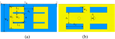
Figure 1: The geometry of the E-shaped MIMO antenna: (a) front view and (b) back view.
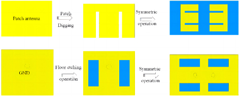
Figure 2: Steps of the antenna design.
Table 1: Dimensions of the optimized antenna structure (unit: mm)
| Parameter | Numerical Value | Parameter | Numerical Value |
| 20 | 40 | ||
| 15.7 | 10.4 | ||
| 4 | 12 | ||
| 2.6 | 2 | ||
| 2 | 6.5 | ||
| 8 | a | 6 |
Figure 1 shows the geometry of the two-cell compact E-shaped MIMO antenna proposed in this paper. Both patches are printed on a FR4 (dielectric constant of 4.4, dielectric loss angle tangent of 0.02) substrate with a volume of 20 mm 40 mm 1.6 mm. And the overall size of the antenna is very small. The antenna structure is firstly to etch the corresponding number of rectangular slots on the single rectangular patch and on the floor respectively so that the proposed single structure achieves the purpose of miniaturization of the antenna patch unit and expansion of its operating bandwidth, and finally, the single radiating patch unit is closely arranged in a symmetric way to form the MIMO two-cell antenna array structure, and the overall design steps are shown in Fig. 2. This is also the difference between the structure proposed in this paper and the previous character-based structure. During the antenna design process, the antenna structure dimensions are modeled and optimized using HFSS electromagnetic simulation sofeware, and the final determined antenna parameters are summarized in Table 1.
III. MTM UNIT DESIGN AND ANALYSIS
A. MTM cell design
The electromagnetic properties of artificial MTMs mainly depend on their structure and dimensions, and by designing their structure and dimensions, the metallic ohmic loss and dielectric loss near the resonance frequency can be adjusted to realize the absorption of incident electromagnetic waves. In this paper, we design a MTM unit structure that can exhibit special electromagnetic resonance characteristics near 5.8 GHz, as shown in Fig. 3. The overall size of the designed MTM structure is very small, and the parameters optimized after simulation are a 5.5 mm, c t 0.4 mm, 0.6 mm, = 0.7 mm, 2 mm.
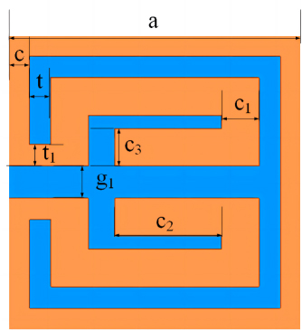
Figure 3: MTM unit structure diagram.
In order to verify the electromagnetic characteristics of the designed MTM unit, the electromagnetic simulation software HFSS is used for detailed analysis. Open resonant circular and square rings are placed on the upper and lower surfaces of FR4 dielectric substrate with thickness of h 1.6 mm, and the whole is placed in an air box. In the simulation, the upper and lower surfaces perpendicular to the z-axis are set as wave-port excitation, the front and rear surfaces perpendicular to the x-axis are set as ideal magnetic conductors (Perfect H), and the left and right surfaces perpendicular to the y-axis are set as ideal electric conductors (Perfect E). At this time, the magnetic field is perpendicular to the surface of the MTM cell, which is used to simulate the generation of the magnetic resonance when the magnetic field passes through the cell, as shown in Fig. 4.
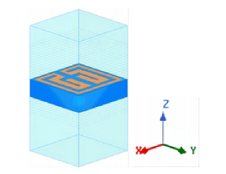
Figure 4: A 3D view of the MTM cell structure.
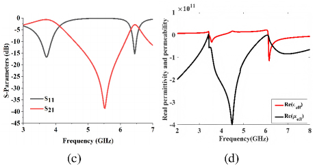
Figure 5: (a) Plot of the S-parameter structure and (b) plot of the extracted equivalent parameter values.
B. Simulation analysis
The MTM is characterized by a normally incident X-polarized wave and a scattering parameter extracted from a single unit cell with periodicity. In order to obtain the characteristic parameters of the MTM, the S parameter inversion method [19, 20] is needed. Figures 5 (a) and (b) show the magnitude of the S-parameter of the MTM cell structure and the equivalent parameter values of its permeability and permittivity, respectively. From the results, it can be seen that the value of its equivalent magnetic permeability at 5-6 GHz is negative, and the value of the equivalent permitivity is positive, which can indicate that the MTM is an electronegative material. It can be observed from the transmission and reflection characteristics that the MTM has a determined suppression bandwidth between 5-6 GHz, especially a transmission stop band due to magnetic resonance near the center frequency point 5.8 GHz. It can be used to suppress the propagation of coupling current from one antenna element to another to improve isolation between antenna array elements.
IV. ANALYSIS OF THE OVERALL MIMO ANTENNA STRUCTURE AND THE EXPERIMENTAL RESULTS
The purpose of decoupling is achieved by loading the 1 × 3 MTM array structures between the two radiation patches, and the overall antenna structure is shown in Fig. 6. To make the measurements comparable, the original and loaded MTM antennas adopt the same structural dimensions, where 0.4 mm, 0.5 mm.
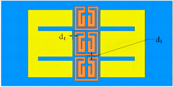
Figure 6: Front view of the integral MIMO antenna loaded with MTMs. (Blue is the dielectric substrate, the radiation patch is yellow and the MTM structure on the same surface as the radiation patch is orange).
A. S-parameter simulation analysis
Figure 7 is a comparison diagram of the antenna S-parameters obtained by the HFSS software simulation. Figure 7 (a) shows that the central working frequency of the MIMO antenna loaded with MTMs is slightly shifted to the low frequency, but the overall deviation of the working frequency band is not large. It can be seen from Fig. 7 (b) that by loading MTMs, the coupling coefficient obtained a substantial decrease of the MIMO antenna in the entire working frequency band. Compared with the original antenna, the coupling degree not only achieves the minimum requirement of the MIMO antenna but also achieves a maximum of 10 dB decoupling, and the coupling reduction effect is remarkable.
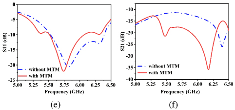
Figure 7: S-parameter plot of the antenna: (a) and (b) .
B. 2D radiation pattern
Figure 8 shows a comparison of the two-dimensional far-field radiation pattern of the antenna before and after loading the MTM structure in the E-plane and H-plane at 5.8 GHz. As can be seen from the comparison figures, compared with the ordinary MIMO antenna, the directional map of two-dimensional far-field radiation in the H-plane of the MIMO array antenna loaded with MTMs is unchanged, indicating that the introduction of the MTMs does not damage the far-field radiation characteristics of the antenna. In addition, it can be seen from Fig. 8 (a) that adding MTM enhances the main flap radiation of the far-field radiation of the antenna’s E-plane more obviously. That is, the MIMO antenna without MTM produces large side lobe radiation between 120 and 180 degrees. Instead, the MIMO antenna with MTM produces strong main lobe radiation in the direction of 150 degrees. The side lobe radiation at this time is very small, which further indicates that the MTM structure has a significant role in improving the performance of the MIMO antenna.
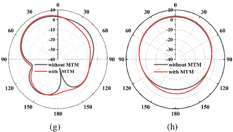
Figure 8: Radiation pattern of the antenna with and without MTM: (a) E-plane and (b) H-plane.
C. Antenna surface current distribution
In order to understand the decoupling principle of the loaded MTM antenna more intuitively, the surface current distribution of the antenna before and after the loading of the MTM is analyzed at the center frequency point of 5.8 GHz, and the comparison results are shown in Fig. 9. In order to make a visual comparison, the same current intensity scale has been chosen for both figures, with darker colors (red) indicating a denser distribution of current intensity on the surface, and lighter colors (blue) indicating a sparser distribution of current intensity on the surface, where the left figure is the case not based on MTMs, and the right figure is the case based on MTMs. From the comparative analysis of the left and right figures, it can be seen that the surface current strength distribution on the antenna array element in the left figure is denser, which can produce stronger coupling to the neighboring antenna array elements, whereas in the right figure, after the addition of the MTM structure in the middle of the two antenna units, the surface current strength distribution on the following antenna array element becomes obviously sparse, which further indicates that the designed MTMs can effectively weaken the electromagnetic mutual coupling between two closely spaced antenna elements.
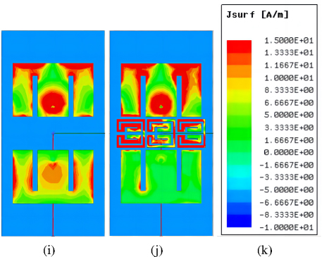
Figure 9: Surface current map at 5.8 GHz: (a) without MTMs, (b) with MTMs and (c) current intensity distribution.
D. 3D radiation gain direction map of the antenna
A comparison of the 3D radiation gain directional map of the antenna at the center frequency point 5.8 GHz generated in the electromagnetic simulation software is shown in Fig. 10. From the figure, it can be seen that the addition of the MTM has an effect on the antenna gain, that is, it increases the antenna gain by a small amount, with an overall increase of 1.05 dB. From the 3D radiation gain direction map, the highest gain of the antenna reaches 5.89 dB, which meets the range requirements of 5G mobile communication antennas for highgain.
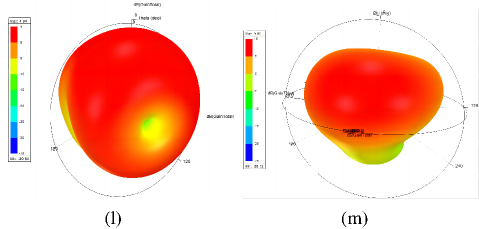
Figure 10: 3D gain orientation diagram: (a) without MTMs and (b) with MTMs.
E. Gain and efficiency of proposed antenna
Figure 11 shows the resulting plot of the gain and efficiency of the MIMO antenna after loading the MTM. We can see from the figure that the peak gain ranges from 4.08 dBi to 5.95 dBi. The radiation efficiency ranges from 66% to 80% in the entire operating frequency band, and the radiation efficiency at the center frequency of 5.8 GHz is about 80%. The maximum gain is 5.95 dBi at 5.9 GHz and the minimum gain is 4.08 dBi at5.36 GHz.
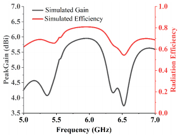
Figure 11: Gain and efficiency of proposed antenna.
F. The MIMO antenna diversity characteristics
ECC and diversity gain are the two most important parameters to show the diversity characteristics of MIMO antenna. Figure 12 presents the simulated ECC and diversity gain diagram of MIMO antenna. It can be seen from the figure that the ECC value meets the minimum requirements of the ideal value in the entire working band, and the overall ECC is less than 0.02 in the working band. This confirms that the designed MIMO antenna has good isolation and the best performance under a multipath fading environment. Moreover, in the working frequency band, the proposed MIMO antenna achieves a diversity gain of 10 dBi with good diversity characteristics.
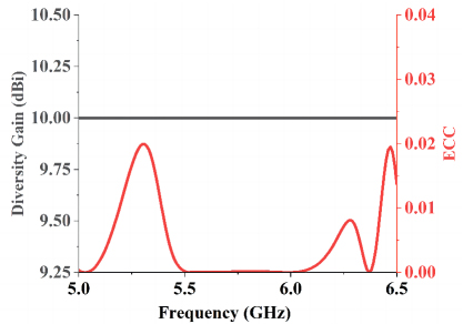
Figure 12: Gain and efficiency of proposed antenna.
Table 2: Comparison between the proposed antenna and other antennas
| Ref | Electrical Dimensions | Center Frequency Point (GHz) | Bandwidths (GHz) | Isolation (GHz) | Gain (GHz) |
| [21] | 0.57×0.385 | 6, 8, 10 | 5.2-10.6 (68.35%) | <-15 | 5.7 |
| [22] | 1.07×1.07×0.01 | 2.3, 2.5, 2.65 | 2.22-2.75 (21.3%) | <-18 | 5.5 |
| [23] | 0.44×0.5 | 3.5 | 3.22-4.36 (30.07%) | Not Given | 5.2 |
| [24] | 0.81×0.5×0.02 | 2.45 | 2.449-2.456 (0.29%) | <-22 | 6.68 |
| [25] | 0.4×0.61×0.01 | 2.77 | 2.73-2.85 (4.3%) | <-50 | Not Given |
| [26] | 0.84×1.01 | 3.5 | 3.5-3.55 (1.42%) | <-20 | Not Given |
| This paper | 0.66×0.33×0.02 | 5.8 | 5.32-6.02 (12.35%) | <-18 | 5.89 |
G. Comparative analysis of antenna array elements
The MIMO antenna arrays presented in Table 2 have similarities in shape, and their performance is compared in this section. Compared with [21, 22, 23], the structure in this paper has advantages in isolation and gain although the bandwidth is relatively narrower. Although the design has disadvantages in isolation compared with [24, 25, 26], the operating bandwidth is relatively wider. Compared with these four antenna arrays, the antenna structure has a greater advantage in terms of small size, which is better able to meet the demand of modern mobile devices on the antenna miniaturization. In addition, the comparison of the electrical dimensions of the antennas is more reflective of the smaller dimensions of the proposed antennas. Therefore, the design can meet the most basic requirements of the antenna in high isolation, small size, broadband and highgain.
V. ANTENNA FIELD MEASUREMENT AND RESULT
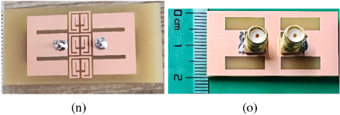
Figure 13: Physical representation of an antenna loaded with MTMs: (a) front view and (b) back view.
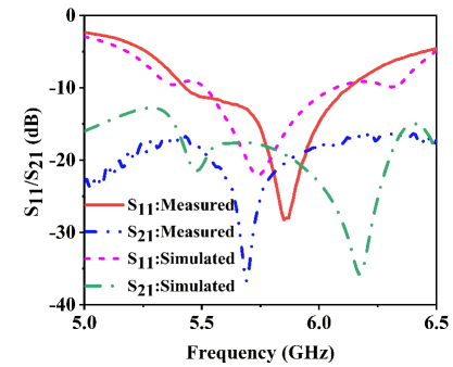
Figure 14: Measured and simulated S-parameters of the designed MIMO antenna.
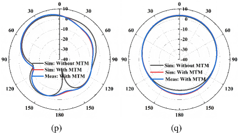
Figure 15: Measured and simulated radiation pattern(with or without MTMs) at 5.8 GHz: (a) Phi 0 C and (b) Phi 90 C.
To validate the proposed design, an antenna prototype was made and measured. The antenna was simulated using ANSYS HFSS. The antenna made according to the above parameters is shown in Fig. 13, and the S parameter of the antenna was measured using the Network Analyzer (NA). The measured and simulated values of the S parameters are shown in Fig. 14. Comparing the simulation results and the measured results, we find that there is a small frequency shift. This may be due to factors such as SMA connector loss, cable loss, and radiation boundary during measurement. The measured results show that the measured frequency band of the proposed MIMO antenna of <-10 dB is basically unchanged and <-20 dB. And the measured and simulation results are generally moderate.
Next, the radiation characteristics of MIMO antenna in both cases (with or without MTMs) were further studied. Figure 15 shows the simulation and measured radiation pattern of the main plane azimuth (Phi 0 C) and pitch (Phi 90 C) at 5.8 GHz, which shows that the introduction of the MTM has a slight effect on the deviation of the radiation pattern.
VI. CONCLUSION
In this paper, a symmetric “E-shaped” MIMO dual-cell array antenna for 5G WLAN band is proposed by combining the character-shaped radiating patch and MIMO technology to optimize the shortcomings of a single patch antenna, such as low spectrum utilization. A kind of “concave” shaped MTM cell structure is proposed to improve the isolation degree between two antenna cells, which is mainly placed between two radiating patches in a 1 × 3 arrangement. The distance from the MTM array structure to the two patch cells can be adjusted to reduce the coupling degree between the MIMO antenna array cells. Comparison of the measured and simulated results shows that the introduction of MTM improves the impedance matching characteristics of the antenna array compared with the original antenna and steadily improves the gain of the antenna. Although the gain improves less, the overall gain meets the minimum requirements of high gain. Meanwhile, the isolation degree is above -18 dB throughout the operating frequency band, and achieves a maximum of 10 dB decoupling compared to the antenna array without MTM. Compared with the same type of antenna, the antenna has some advantages in terms of miniaturization, gain and isolation. Therefore, the proposed MIMO antenna system is suitable for the field of miniaturized MIMO dual array antennas with high isolation.
ACKNOWLEDGMENT
This research was funded by the doctoral research startup fund of Northeast Electric Power University, and project number is BSIXM-2021207. This paper was funded by the National Natural Science Foundation of China (61803356).
REFERENCES
[1] G. J. Foschini, “Layered space-time architecture for wireless communication in a fading environment when using multi-element antennas,” Bell Labs Technical Journal, vol. 1, no. 2, pp. 41–59, 1996.
[2] A. J. Paulraj, D. A. Gore, R. U. Nabar, and H. Bolcskei, “An overview of MIMO communications - a key to gigabit wireless,” Proceedings of the IEEE, vol. 92, no. 2, pp. 198–218, 2004.
[3] J. Kulkarni, A. Desai, and C. Y. D. Sim, “Wideband Four-port MIMO antenna array with high isolation for future wireless systems,” AEU: Archiv fur Elektronik und Ubertragungstechnik: Electronic and Communication, vol. 128, p. 153507, 2021.
[4] T. Jiang, T. Jiao, and Y. Li, “Array mutual coupling reduction using L-loading E-shaped electromagnetic band gap structures,” International Journal of Antennas and Propagation, vol. 2016, no. pt.2, pp. 6731014.1–6731014.9, 2016.
[5] Y. Q. Zheng and M. Gao, “A wideband back-to-back U-shaped monopole antenna,” Microwave and Optical Technology Letters, vol. 61, no. 7, pp. 1815–1820, 2019.
[6] A. G. Koutinos, D. E. Anagnostou, R. Joshi, S. K. Podilchak, G. A. Kyriacou, and M. T. Chryssomallis, “Modified easy to fabricate E-shaped compact patch antenna with wideband and multiband functionality,” IET Microwaves Antennas & Propagation, vol. 12, no. 3, pp. 326–331, 2017.
[7] K. Yu, Y. Li, X. Luo, and X. Liu, “A modified E-shaped triple-band patch antenna for LTE communication applications,” in IEEE International Symposium on Antennas and Propagation, pp. 295–296, 2016.
[8] H. Cao, Y. Z. Xie, and Y. Y. Wu, “A miniaturized MIMO antenna with polarization converter for reduction of RCS and mutual coupling,” in 2024 IEEE MTT-S International Wireless Symposium (IWS), 2024.
[9] A. A. Khan, S. A. Naqvi, M. S. Khan, and B. Ijaz, “Quad port miniaturized MIMO antenna for UWB 11 GHz and 13 GHz frequency bands,” AEU - International Journal of Electronics and Communications, p. 153618, 2021.
[10] L. Liu, S. W. Cheung, and T. I. Yuk, “Compact MIMO antenna for portable devices in UWB applications,” IEEE Transactionson Antennas and Propagation, vol. 61, no. 8, pp. 4257–4264, 2013.
[11] W. J. Liao, S. H. Chang, J. T. Yeh, and B. R. Hsiao, “Compact dual-band WLAN diversity antennas on USB dongle platform,” IEEE Transactionson Antennas and Propagation, vol. 62, no. 1, pp. 109–118, 2014.
[12] G. Saxena, P. Jain, and Y. K. Awasthi, “High isolation EBG based MIMO antenna for X-band applications,” 2019 6th International Conference on Signal Processing and Integrated Networks (SPIN), pp. 97–100, 2019.
[13] M. F. Ismail, M. K. A. Rahim, N. A. Samsuri, N. A. Murad, and A. A. Pramudita, “High isolation MIMO antenna using electromagnetic band gap - EBG structure,” 2021 International Symposium on Antennas and Propagation (ISAP), pp. 1–2, 2021.
[14] M. A. Abdalla and A. A. Ibrahim, “Compact and closely spaced metamaterial MIMO antenna with high isolation for wireless applications,” IEEE Antennas & Wireless Propagation Letters, vol. 12, pp. 1452–1455, 2013.
[15] B. A. F. Esmail and M. SlawomiKoziel, “Design and optimization of metamaterial-based dual-band 28/38 GHz 5G MIMO antenna with modified ground for isolation and bandwidth improvement,” IEEE Antennas and Wireless Propagation Letters, vol. 22, pp. 1069–1073, 2023.
[16] C. Abdelhamid, M. Daghari, H. Sakli, and C. Hamrouni, “High isolation with metamaterial improvement in a compact UWB MIMO multi-antennas,” in 2019 16th International Multi-Conference on Systems, Signals & Devices (SSD), Istanbul, Turkey, pp. 514-517, 2019.
[17] X. Zheng, T. Jiang, H. Lu, and Y. Wang, “Double-layer microstrip band stop filters etching periodic ring electromagnetic band gap structures,” Electronics, vol. 9, no. 8, p. 1216, 2020.
[18] X. Zheng and T. Jiang, “Triple notches bandstop microstrip filter based on archimedean spiral electromagnetic bandgap structure,” Electronics, vol. 8, no. 9, pp. 964–, 2019.
[19] X. Chen, T. M. Grzegorczyk, B. I. Wu, J. Pacheco, and J. A. Kong, “Robust method to retrieve the constitutive effective parameters of metamaterials,” Physical Review E, vol. 70, 2004.
[20] A. B. Numan and M. S. Sharawi, “Extraction of material parameters for metamaterials using a full-wave simulator [Education Column],” IEEE Antennas & Propagation Magazine, vol. 55, pp. 202–211, 2013.
[21] W. Li, W. Xue, and Y. Li, “A wideband Zhong-shaped MIMO antenna,” 2021 IEEE International Workshop on Electromagnetics: Applications and Student Innovation Competition (iWEM), pp. 1–2, 2021.
[22] J. Jianfeng, “Design and research of wideband MIMO antenna based on meta-materials,” Harbin: Harbin Engineering University, pp. 43–56, 2021.
[23] R. Kumar, N. Nasimuddin, and R. K. Chaudhary, “A new dual C-shaped rectangular dielectric resonator based antenna for wideband circularly polarized radiation,” International Journal of RF and Microwave Computer-Aided Engineering, vol. 29, no. 6, pp. e21672.1–e21672.12, 2019.
[24] Z. Niu and H. Zhang, “Isolation enhancement in Chinese character antenna array using simple defect ground structure,” International Journal of RF and Microwave Computer‐Aided Engineering, vol. 29, no. 11, 2019.
[25] S. Luo, Y. Li, and X. Mao, “Isolation enhancement of a two-element MIMO antenna array using rotated E-shaped resonators,” in 2017 Progress in Electromagnetics Research Symposium - Fall (PIERS - FALL), pp. 262–265, 2018.
[26] X. M. Yang, X. G. Liu, X. Y. Zhou, and T. J. Cui, “Reduction of mutual coupling between closely packed patch antennas using waveguided metamaterials,” IEEE Antennas and Wireless Propagation Letters, vol. 11, pp. 389–391, 2012.
BIOGRAPHIES

Xuemei Zheng Ph.D., Associate Professor and Master’s Supervisor in Information and Communication Engineering at Northeast Electric Power University. Main research directions: MIMO antennas, microstrip device design, array antennas, high isolation microstrip antennas, antenna beamforming technology, electromagnetic compatibility analysis, and other aspects.

Ziwei Zhao received the B.S. degree from the Inner Mongolia University of Technology in 2022. She is currently pursuing the M.S. degree in Information and Communication Engineering at Northeast Power University. Her research interests include multi-input multi-output antennas, microstrip antennas, array antennas, and high isolation microstrip antennas.

Yuwen Pan Nanjing Sainty-tech Communications Ltd., microstrip device testing and analysis.

Tongchao Zhang received his B.E. degree from the Shenyang Institute of Engineering in 2023. He is currently pursuing his M.S. degree in information and communication engineering at Northeast Power University. His main research areas include MIMO antennas, microstrip antennas, array antennas, highisolation microstrip antennas, and antenna decoupling technology.
ACES JOURNAL, Vol. 39, No. 12, 1051–1058
doi: 10.13052/2024.ACES.J.391203
© 2024 River Publishers