Integral Sliding Mode Control with Exponential Approximation Law for an AMB Rotor System Considering the Alford Force
Siyuan Zhang and Jin Zhou
1Department of Marine and Electrical Engineering
Jiangsu Maritime Institute, Nanjing 210000, China
zhangsiyuan@nuaa.edu.cn
2Department of Mechanical and Electrical Engineering
Nanjing University of Aeronautics and Astronautics, Nanjing 210000, China
zhj@nuaa.edu.cn
Submitted On: June 20, 2024; Accepted On: October 12, 2024
ABSTRACT
In order to deal with the nonlinear problems associated with the Alford force and active bearing rotor system in fluid machinery, an integral sliding mode control with exponential reaching law is proposed in this paper. An integral term is incorporated into the switching function, and an exponential approaching law, along with a boundary layer saturation function that replaces the symbolic function, is adopted to suppress the chattering and tracking error of sliding mode control. Simulation and experimental results show that, under the magnetic bearing force and Alford force, the system exhibits improved anti-disturbance performance compared to a PID controller. Moreover, the rotor amplitude is reduced by 33% when using this controller. The proposed controller demonstrates good dynamic performance and strong robustness, even when the parameters of the entire system are perturbed.
Index Terms: Active magnetic bearings, Alford force, Sliding mode control, Vibration control.
I. INTRODUCTION
An active magnetic bearing (AMB) is widely used in fluid machinery because of its advantages of no mechanical contact, no friction and wear, longer life, high efficiency and active control [1]. Nevertheless, issues during the manufacturing and assembly process can result in relative eccentricity between the impeller and volute. When the magnetic suspension fluid machinery operates at high speeds, a differential pressure is generated in the circumferential direction of the impeller. This differential pressure creates a transverse force acting on the rotor [2], commonly referred to as the Alford force. The Alford force can potentially induce instability in the equipment.
Generally, the rotor cannot remain suspended at the center due to multiple disturbances, which causes the electromagnetic force of the AMB to exhibit strong time-variant and nonlinear characteristics. What’s more, the Alford force aggravates the nonlinearity which makes the controller more difficult and complicated. Shata et al. [3] and Anantachaisilp and Lin [4] applied a fractional order PID controller to the magnetic bearing rotor system and optimized the control parameters. The effect of the improved PID controller was verified by comparative experiment. Raafat and Akmeliawati [5] developed a robust H2/H controller for AMB systems by employing adaptive neuro-fuzzy inference systems (ANFIS) for intelligent uncertainty estimation, thereby achieving wide bandwidth and enhanced performance while accurately compensating for modeling errors and nonlinearities Ran et al. adopted H [6] and [7] controllers, and their research confirmed that by using these two controllers, rotor vibration was effectively suppressed and successfully passed through the critical speed. Di and Lin [8] applied the all-coefficient adaptive control (ACAC) to control the flexible magnetic bearing rotor and the orbit was smaller than . This method did not rely on modeling accuracy, which is simpler to realize compared with H and . Guan et al. [9] introduced extended state observer (ESO) into the adaptive controller and used it in magnetic bearing rotor systems. Research showed that the controller can significantly suppress interference in thesystem.
As a robust controller, sliding mode control (SMC) is suitable for dealing with nonlinear systems and remains insensitive to variations in parameters and external disturbances. In recent years, SMC has been widely used in magnetic bearings. Chen and Lin [10] presented a robust nonsingular terminal sliding mode control. Compared with the conventional sliding mode control with linear sliding surface, it provides faster, finite time convergence, and higher control precision. Huynh and Tran [11] designed a new integral sliding mode control for the 3-pole AMB system and demonstrated the efficacy of the proposed method. Rong and Zhou [12] built an adaptive backstepping sliding mode control for a zero-bias current AMB system and the effectiveness was verified by simulation and experiment. Mystkowski [13] dealt with sliding mode nonlinear observers and designed a Lyapunov sliding mode observer for a flux-controlled AMB. The stability and effectiveness of the proposed observer-based feedback were verified by means of numerical simulations. Rahmatullah and Serteller [14] employed SMC for DC motor speed control, investigating its performance and parameter effects in MATLAB/Simulink, and compared its effectiveness with Fuzzy Logic Control, PID and PI methods.
However, the aforementioned research primarily focuses on internal disturbance within the AMB rotor system, with relatively little attention given to the effects of external disturbance. In this paper, an integral sliding mode control with an exponential approximation law is implemented to solve the Alford force disturbance in magnetic suspension fluid machinery. The switching function is augmented with an integral term, and an exponential approach, along with a boundary layer saturation function, is adopted in place of the symbolic function. This approach suppresses chattering and tracking errors in the sliding mode control, thereby enhancing the system’s anti-disturbance performance. Using a five degrees of freedom AMB rotor system rig as the test object, the effectiveness of this controller is demonstrated through comparison with a PID controller.
II. FUNDAMENTALS
A. Modeling of the AMB rotor system considering the Alford force
The AMB rotor system is divided into five degrees of freedom in radial and axial directions. The radial AMB offers two translational and two rotational degrees of freedom, while the axial AMB provides one translational degree of freedom. The axial rotational degree of freedom is enabled by the motor. In this paper, modeling analysis and controller design for the AMB rotor system are conducted to validate the effectiveness of the controller. Figure 1 shows the model of an AMB rotor system.
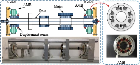
Figure 1: AMB rotor system.
By using Newton’s law and ignoring the influence of gravity, the dynamic model of a magnetic bearing rotor system can be described as follows:
| (1) |
where is acceleration, m is the mass of the rotor, F is the electromagnetic force and defined in equation (3), Fis Alford force and defined in equation (4), and F is various disturbances.
The electromagnetic force of a magnetic bearing is driven by the power amplifier in the form of current difference [1]:
| (2) | |||
where the Taylor expansion of the above equation at i 0, x 0 and ignoring the higher-order term, the magnetic bearing force on the rotor can be expressed as:
| (3) |
where is vacuum permeability, A is area of a single magnetic pole, N is total number of turns of the coil on a pair of magnetic poles, C is unilateral air gap when the rotor is at the magnetic center, i is coil bias current, i is coil control current, x is rotor displacement, kis displacement stiffness coefficient, x is displacement signal, and k is current stiffness coefficient.
The Alford force model can be expressed as [15]:
| (4) | ||
| (5) | ||
| (6) | ||
| (7) |
where e is eccentricity, R is tip radius, R is root radius, is inlet angle, is outlet angle, is airflow density, is speed coefficient, is average tip clearance, and V is inlet speed.
If equation (3) is substituted into equation (1):
| (8) |
then, according to the state-space representation of the system, equation (9) is obtained as follows:
| (9) |
The block diagram of an AMB rotor system considering the Alford force is shown in Fig. 2. In the AMB rotor system, significant nonlinear perturbations arise from a variety of disturbances. This paper presents the design of a sliding mode controller equipped with an exponential approach law, which can still maintain the characteristics of low overshoot, rapid response, and strong robustness in the case of multi-source external disturbances.
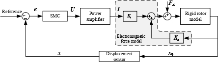
Figure 2: AMB rotor system considering the Alford force.
B. SMC design for an AMB system
Exponential reaching law sliding mode control can guarantee the quality of sliding mode control and weaken chattering to a certain extent [16]. Guo and Bo [17] proposed a new exponential reaching law based on the traditional exponential reaching law, enhancing the robustness of the control system. Wang et al. [18] designed a new variable exponential reaching law, introducing system state variables into the constant velocity term, which accelerates the reaching speed while reducing the system chattering, but the overshoot issue was not resolved. Wang et al. [19] introduced a weighted integral term based on the variable exponential reaching law, eliminating the system overshoot.
Based on the above analysis, an exponential reaching integral sliding mode control method will be utilized to design the controller, including the design of the sliding surface function and the control law for the sliding mode reaching phase, and further analysis of the system’s robustness will be conducted.
Controller design
To enhance the tracking performance of the control system and to eliminate the steady-state error, integral action is incorporated into the sliding mode switching function. Equation (10) can be rewritten as follows:
| (11) |
where c is integral sliding mode gain.
If we define the tracking error and its derivative , where x is 0 in the ideal state, then the sliding mode switching function is defined as:
| (12) |
Neglecting other external interference factors, substituting this into the preceding equation yields:
| (13) |
Due to the characteristics of the AMB rotor system, the rotor deviates from the equilibrium position when the system boots. To ensure the system reaches the sliding surface without chattering in a short time, an exponential approach law is adopted. The designed exponential approach law is:
| (14) |
By combining and simplifying equations (13) and (14), the subsequent equation is derived:
| (15) |
In practical applications, the use of a symbolic function can result in high-frequency chatter, which may excite additional vibrations within the system, potentially leading to instability. Consequently, it is imperative to mitigate this chatter. In this paper, the saturation function of the boundary layer is used to replace the symbolic function:
| (16) |
where is boundary layer thickness, which indicates that the trajectory of the system is limited to a neighborhood of and the larger the value, the smaller the chattering, but it will make the static error larger and the control effect worse.
Stability analysis
The sufficient condition for ensuring the stability of the system is that the derivative of the Lyapunov function must be less than or equal to zero, which is then substituted into equation (13):
| (18) |
Substitute (12) into (18) and simplify to:
| (19) |
Since the parameters , k are positive, when s0, the equal sign applies, and the aforementioned equation remains consistently less than 0, thus satisfying the Lyapunov stability condition. Consequently, the controller is capable of stabilizing the system.
III. SYSTEM SIMULATION ANALYSIS
In order to test the effect of the SMC proposed in this paper, the controller is verified by Matlab/Simulink. In the simulation, the AMB rotor system parameters are as shown in Table 1.
Table 1: Parameters of an AMB rotor system
| Parameter | Value |
| m (kg) | 14.56 |
| k(N/A) | 338.54 |
| k(N/m) | 2.502e6 |
| R(mm) | 29 |
| R(mm) | 7.5 |
| () | 25 |
| () | 30 |
| V(m/s) | 42 |
To facilitate the tuning process, the impact of three parameters on the controller’s performance was investigated through the application of a step response. The results are depicted in Fig. 3. As observed from Fig. 3, the rise time of the step response tracking decreases with an increase in . Variations in k exhibit minimal influence on the system’s behavior. However, as increases, the overshoot becomes more pronounced, and a certain degree of chattering is observed. The optimized parameters for the improved SMC controller are presented in Table 2.
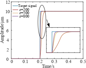
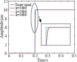
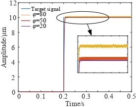
Figure 3: Influence of different parameters on SMC:(a) influence of parameter on SMC, (b) influence of parameter k on SMC, and (c) influence of parameter on SMC.
| Parameter | Value |
| 80 | |
| k | 3000 |
| 10 | |
| c | 500 |
Following the controller tuning, its performance was simulated and experimentally validated. The system was accelerated to 100 Hz, and the rotor orbit was subsequently obtained, as depicted in Fig. 4. The figure illustrates that the radial vibration is effectively controlled within 0.02 V by the improved SMC, signifying the controller’s robust control performance.
Subsequently, the anti-interference performance of the improved SMC was simulated. The Alford force model was introduced for comparison with the PID controller. The rotor’s response to this is presented in Fig. 5. The simulation results indicate that both controllers influence the Alford force, although the improved SMC exhibits a more pronounced effect. In comparison with the PID controller, the amplitude reduction achieved by the enhanced SMC is approximately 25%.
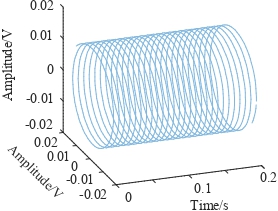
Figure 4: Rotor orbit under SMC.
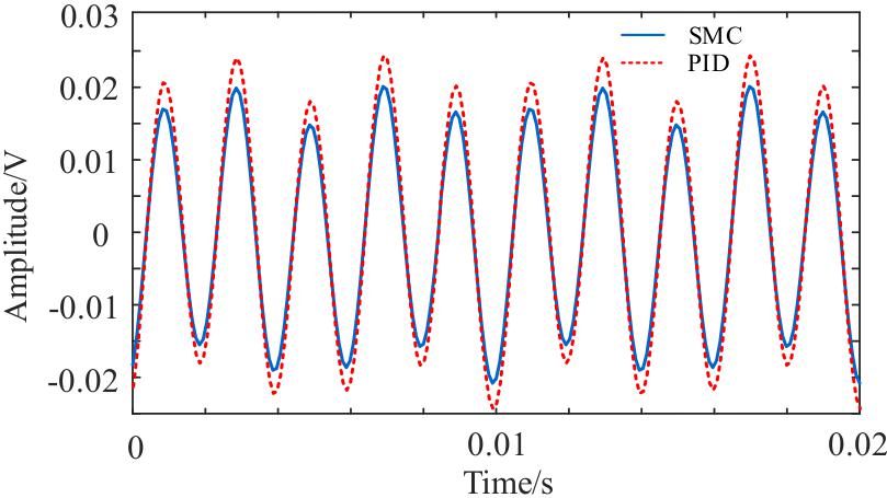
Figure 5: Comparison of rotor responses of different controllers.
IV. EXPERIMENT
To validate the accuracy of the preceding analyses, an AMB test rig was employed for experimental purposes. The experimental apparatus is depicted in Fig. 6.
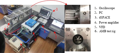
Figure 6: Experimental equipment.
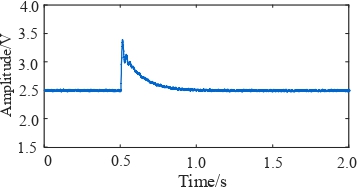
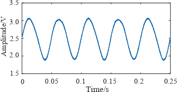
Figure 7: Rotor response to different disturbances under suspension: (a) step interference and (b) sinusoidal interference.
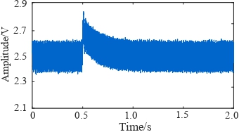
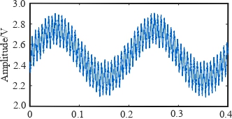
Figure 8: Rotor response to different disturbances under rotating: (a) step interference and (b) sinusoidal interference.
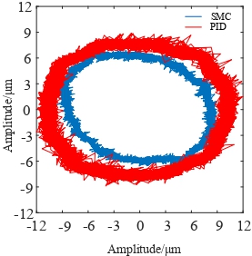
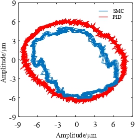
Figure 9: Comparison of rotor orbit of different controllers considering the Alford force: (a) impeller side and (b) non-impeller side.
Initially, step and sinusoidal disturbances were introduced to the rotor while in the suspended state, and the resulting displacement response of the rotor was recorded, as depicted in Fig. 7. The figure clearly indicates that, in the suspended state, the controller exhibits robust performance in the presence of disturbances. The rotor returns to the suspended position within 0.35 s following perturbation by the step signal.
To further substantiate the efficacy of the controller, a rotation experiment was conducted. The rotor’s response to the introduction of step and sinusoidal disturbances is illustrated in Fig. 8. The figure reveals that, in the rotating state, the amplitude is reduced compared to that in the suspended state. This discrepancy is attributed to rotor imbalance and external disturbances present in the rotating state, which necessitate a control effort that generates a compensation quantity counteracting the interference. As a result, the interference is manifest in the vibration displacement, characterized by a quicker response and reduced vibration amplitude.
Finally, the AMB test rig was utilized to simulate the Alford force and to compare the suppression effects of the PID and SMC controllers. The rotor orbit at 100 Hz under the influence of both controllers is depicted in Fig. 9. As shown in Fig. 9 (a), due to the Alford force and flow field effects, the rotor orbit at the impeller side is larger than that at the non-impeller side. Furthermore, the SMC controller outperforms the PID controller, as indicated by a 33% decrease in the rotor orbit amplitude shown in Fig. 9 (b). This demonstrates the superiority and reliability of the designed SMC controller.
V. CONCLUSION
A model of a magnetic bearing rotor system considering the Alford force is established in this paper. On this foundation, an integral sliding mode control with exponential approximation law is designed to solve the system nonlinear and chattering. Moreover, a stability analysis of the system is carried out. Experimental results show that the proposed controller can effectively mitigate chattering and exhibits robust anti-interference ability. It is noteworthy that the rotor orbit at the impeller side is reduced by 33% under the controller presented here, when compared to the performance of the PID controller, highlighting the superiority and significance of this approach for the AMB rotor system.
REFERENCES
[1] G. Schweitzer and E. Maslen, Magnetic Bearing: Theory, Design, and Application to Rotating Machinery. Berlin: Springer, 2009.
[2] J. S. Alford, “Protecting turbomachinery from self-excited whirl,” Journal of Engineering for Power, vol. 87, pp. 333-343, 1965.
[3] A. Shata, R. Hamdy, and A. Abdel-Khalik, “A particle swarm optimization for optimum design of fractional order PID controller in active magnetic bearing systems,” IEEE MEPCON, 2016.
[4] P. Anantachaisilp and Z. Lin, “Fractional order PID control of rotor suspension by active magnetic bearings,” Actuators, vol. 6, no. 1, 2017.
[5] S. M. Raafat and R. Akmeliawati, “Intelligent H2/H robust control of an active magnetic bearings system,” Al-Khwarizmi Engineering Journal, vol. 11, no. 2, pp. 1-12, 2015.
[6] S. Ran, Y. Hu, and H. Wu, “Design, modeling, and robust control of the flexible rotor to pass the first bending critical speed with active magnetic bearing,” Advances in Mechanical Engineering, vol. 10, no. 2, pp. 1-13, 2018.
[7] S. Ran, Y. Hu, H. Wu, and X. Cheng, “Resonance vibration control for AMB flexible rotor system based on -synthesis controller,” Mathematical Problems in Engineering, pp. 1-16, 2018.
[8] L. Di and Z. Lin, “Control of a flexible rotor active magnetic bearing test rig: A characteristic model based all-coefficient adaptive control approach,” Control Theory and Technology, vol. 12, pp. 1-12, 2014.
[9] X. Guan, J. Zhou, C. Jin, and Y. Xu, “Disturbance suppression in active magnetic bearings with adaptive control and extended state observer,” Proceedings of the Institution of Mechanical Engineers Part I: Journal of Systems and Control Engineering, vol. 234, no. 2, pp. 272-284, 2020.
[10] S. Y. Chen, and F. J. Lin, “Robust nonsingular terminal sliding-mode control for nonlinear magnetic bearing system,” IEEE Transactions on Control Systems Technology, vol. 19, no. 3, pp. 636-643, 2011.
[11] V. V. Huynh and M. H. Q. Tran, “Integral sliding mode control approach for 3-pole active magnetic bearing system,” Applied Mechanics & Materials, vol. 829, pp. 128-132, 2016.
[12] H. Rong and K. Zhou, “Nonlinear zero-bias current control for active magnetic bearing in power magnetically levitated spindle based on adaptive backstepping sliding mode approach,” Proceedings of the Institution of Mechanical Engineers Part C Journal of Mechanical Engineering Science, 2016.
[13] A. Mystkowski, “Lyapunov sliding mode observers with application for active magnetic bearing operated with zero-bias flux,” Journal of Dynamic Systems Measurement and Control, vol. 231, no. 20, 2018.
[14] R. Rahmatullah and N. F. O. Serteller, “SMC controller design for DC motor speed control applications and performance comparison with FLC, PID and PI controllers,” in Intelligent Sustainable Systems (Lecture Notes in Networks and Systems), vol. 579. Singapore: Springer, 2023.
[15] S. Chai, Y. Zhang, and Q. Qu, “An analysis on the air exciting-vibration force of steam turbine,” Engineering Science, vol. 3, no. 04, pp. 68-72, 2001.
[16] W. B. Gao, Theory and Design Method for Variable Sliding Mode Control. Beijing: Science Press, 1996.
[17] X. D. Guo and D. Bo, “A PMSM sliding mode control system based on a novel exponential reaching law,” Control Engineering of China, vol. 25, no. 10, pp. 1865-1870, 2018.
[18] A. Wang, X. Jia, and S. Dong, “A new exponential reaching law of sliding mode control to improve performance of permanent magnet synchronous motor,” IEEE Transactions on Magnetics, vol. 49, no. 5, pp. 2409-2412, 2013.
[19] Q. M. Wang, C. H. Jiang, and M. J. Xie, “Permanent magnet synchronous motor control with composite variable exponent reaching law,” Micromotors, vol. 54, no. 7, pp. 99-103, 2021.
BIOGRAPHIES

Siyuan Zhang was born in Jiangsu, China, in 1992. He received the Ph.D. degree from the Nanjing University of Aeronautics and Astronautics (NUAA). He has been working in the Jiangsu Maritime Institute (JMI) since 2023. His research interests include magnetic bearings and vibration control.

Jin Zhou was born in Jiangsu, China, in 1972. She received the Ph.D. degree in mechanical engineering from the China University of Mining and Technology (CUMT), China, in 2001. From 2012 to 2013, she was a Visiting Scholar in the Rotating Machinery and Control Laboratory (ROMAC) of the University of Virginia. She was the member of Program Committee of the 14th International Symposium on Magnetic Bearings (2014) and the Program Chair of the 16th International Symposium on Magnetic Bearings (2018). She was an elected member of International Advisory Committee for ISMB in 2018. Her research interests include magnetic bearings and vibration control.
ACES JOURNAL, Vol. 39, No. 9, 841–847
doi: 10.13052/2024.ACES.J.390910
© 2024 River Publishers