Large Angle Electronically Controlled Beam Scanning Antenna Based on Liquid Crystal
Wei Hu1, Di Jiang1, Jiahao Zhao1, Chenqi Zhang1, Guhaolan Zhao1, Jiacheng Zhao1, Bo Yan1, Chuanpei Xu2, and Guofu Wang3
1Information and Communication Engineering
University of Electronic Science and Technology of China, Chengdu 611731, China
weihu_2021@163.com, dijiang@uestc.edu.cn, zjh17732991106@163.com, chenqizhang_00@163.com, zghl_work@163.com, lyang_26@163.com, boyan@uestc.edu.cn
2Guilin University of Electronic Technology
Guilin, Guangxi 541004, China
Xuchuanpei@163.com
3Guangxi University of Science and Technology
Liuzhou, Guangxi 545006, China
guofwang@126.com
Submitted On: July 04, 2024; Accepted On: July 24, 2025
ABSTRACT
In this paper we propose a miniaturized large-angle beam scanning phased array antenna using liquid crystal. We innovatively combine the liquid crystal electrically tunable structure with the wide-beam antenna element structure and design an integrated multi-layer antenna structure which realizes large-angle beam scanning within the working bandwidth. The problems of low beam control accuracy and narrow scanning angle of traditional array antenna are effectively addressed. The overall dimensions of the prototype are 74604 mm. Based on the test results of the prototype the gain has reached 20.2 dBi at 27 GHz and the scanning angle was greater than 60∘.
Keywords: Large-angle beam scanning, liquid crystal, miniaturization, phased array antenna.
I. INTRODUCTION
In recent years, antennas in wireless communication systems are required to meet the requirements of many high performances, such as high gain pattern, wide-beam scanning angle and wide bandwidth. A phased array antenna has the functions of beam scanning, beam control, and anti-interference. As a representative of high-performance antenna, phased array antenna have been widely studied, and play an important role in vehicle radar, satellite radar, 5G mobile terminal and other fields. As a key device of phased array, the phase shifter makes the beam superposition in a specific direction by changing the feed phase of the radiation element to achieve the function of beam forming. The traditional phase shifter unit usually adopts PIN diode-based phase shifters [1, 2, 3, 4, 5, 6], varactor diode-based phase shifters [7, 8], digital phase shifters [9, 10], ferrite-based phase shifters [11] and other methods [12, 13, 14, 15] to achieve phase shift, among which PIN diode and varactor-diode based phase shifters have high insertion loss and can only achieve step phase shift. Although a digital phase shifter has higher phase shift accuracy, the cost and volume increase exponentially with the increase of phase shift accuracy, which is not conducive to large-scale array and miniaturization. As a tunable material, ferrite can realize continuous phase shift, but its high insertion loss limits its application in high frequency. Therefore, how to design a continuously tunable phase shifter and the associated matching antenna system is vital to develop a new generation of phased array antennas.
Liquid crystal, as a new passive tunable material, exhibits obvious polarity under electric field, so it has the ability to continuously tune permittivity under bias voltage. The thermal expansion coefficient of liquid crystals is usually between 10-5/K and 10-6/K. This numerical range indicates that the size change of liquid crystal materials is relatively small when the temperature changes. This dimensional stability makes liquid crystals an ideal material for manufacturing high-precision optical instruments and high-precision antennas. Liquid crystal molecules have an ordered arrangement structure, which makes liquid crystals exhibit anisotropy in physical properties. Compared to some lumped phase-shifting devices, liquid crystal devices have no parasitic effects in higher frequency bands and have smaller losses. This feature enables liquid crystal antennas to maintain high efficiency and less energy loss when transmitting signals.
This study demonstrates a liquid crystal based phased array antenna with significant innovations in both architecture and performance. We propose a novel integrated structure combining a wide-beam dipole radiator array, a high-isolation feed network, liquid crystal-based phase shifting, and a dedicated liquid crystal bias control circuit achieving unprecedented miniaturization while overcoming traditional scan limitations. Experimental validation confirms breakthrough beam-scanning capabilities: continuous 1D scanning over 120∘ with a peak gain of 20.2 dBi.
II. STRUCTURE OF DESIGNED ANTENNA
A. Liquid crystal phased shifter design
In this paper we use a slow wave transmission line as the phase-shifting structure, which is suspended upside down under the first layer substrate, and whose lower surface is in contact with the liquid crystal. The second layer substrate adopts a slot design to contain the liquid crystal, and the third layer substrate is used to print the metal ground and form a bias electrode with the transmission line. By changing the paranoid voltage applied to the metal ground, the dielectric constant of the liquid crystal is controlled, then the transmission coefficient of the electromagnetic wave on the transmission line can be changed, and thus the phase shift can be controlled.
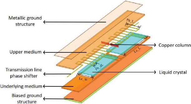
Figure 1: Diagram of liquid crystal phase shifter.
To ensure that the primary working mode of electromagnetic waves passing through the phase shifter remains a quasi-TEM (Transverse Electromagnetic, where both electric and magnetic fields are transverse to the direction of wave propagation) wave and to maximize energy transfer to the output end, the liquid crystal tank is designed in two sections. A row of metal copper columns is placed in the middle, replacing the traditional metal electric wall, to optimize energy confinement within the transmission line. The diameter of the metal copper column is 0.2 mm and the spacing is 0.3 mm, which can effectively reduce return loss and transmission loss. The structure diagram of the designed phase shifter is shown in Fig. 1. The simulation results of the phase shifter base on liquid crystal material are shown in Fig. 2, from which we can see that the maximum phase shift is 410∘ by changing the dielectric constant of the liquid crystal and the insertion loss of the phase shifter is kept within 3 dB, in bandwidth of 26–28 GHz.
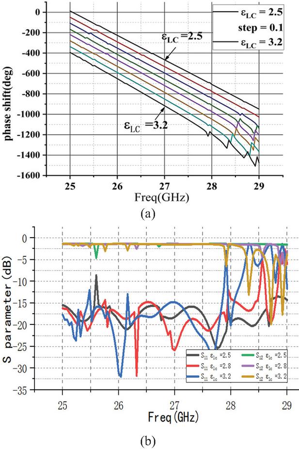
Figure 2: Simulation results of the designed phase shifter: (a) relationship between phase and dielectric constant and (b) S parameter of the phase shifter.
B. Power division network design
To ensure the miniaturization of the power division phase-shifting network while further improving port isolation, we propose a novel network structure. In this design, the power dividers are distributed across different layers, effectively reducing coupling between the transmission lines.
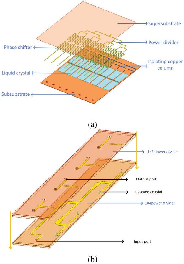
Figure 3: Structure of designed power divide: (a) cascade of phase shifters and power divider and (b) structure of post-phase shifter power division network.
As shown in Fig. 3 (a), a multistage combined Wilkinson power divider is used to realize the cascade of phase shifters after equal phase power divider. The structure of the power divider adopts a copper column to reduce electromagnetic interference and leakage between adjacent lines and improve port isolation. The design of the post-phase shift power division network is shown in Fig. 3 (b). The multi-layer hierarchical power division structure is adopted to reduce the horizontal size to achieve miniaturization. The output end of the phase shifter is cascaded with the upper power divider through eight metallization holes to distribute the power of the post-phase shift signal.
C. Radiation patch design
In this work, we used a binary magnetoelectric dipole antenna to broaden the beam, as shown in Fig. 4. The traditional dipole antenna is divided into a driver patch and a parasitic patch, allowing for more flexible control of the current loop direction and enabling miniaturization of the patch. By increasing the diversity of the direction of the magnetic current, the structure can broaden the beam width by more abundant field distribution around the radiating element. The designed patch antenna demonstrates favorable performance, as shown in Fig. 5. It achieves excellent impedance matching at 27 GHz with a reflection coefficient of 18 dB and delivers a peak gain of approximately 5 dBi at the boresight direction, verifying its effective directional radiation characteristic.
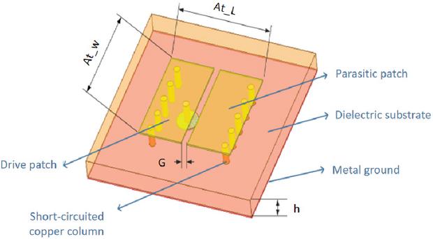
Figure 4: Structure of designed radiation patch.
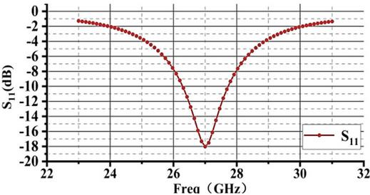
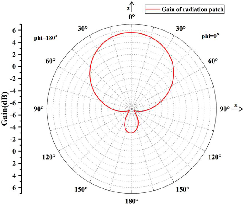
Figure 5: Simulation result of designed antenna patch: (a) S parameter of antenna patch and (b) gain of antenna patch.
D. Array integration design
The phased array adopts an 88 uniform array model structure. A schematic diagram of the array structure is shown in Fig. 6. The array consists of antenna layer, power layer and phase shift power division network layer, and each layer is connected through metallized holes. In addition, in order to further reduce the coupling between the antennas and improve the overall gain, the copper column structure is used as the electric wall between the units to inhibit electromagnetic leakage. By means of simulations, we found that optimal spacing between adjacent array elements is 5.55 mm, and optimal spacing of the decoupled copper columns is 0.3 mm.
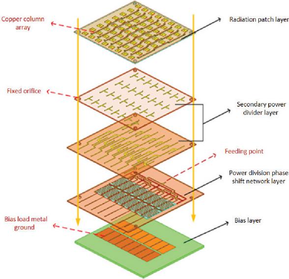
Figure 6: Structure of array antenna multi-layer integration diagram.
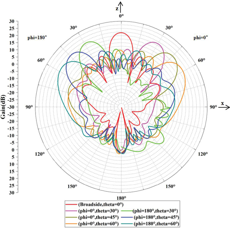
Figure 7: Simulation results of radiation patterns under different dielectric constants at the operating frequency.
Figure 7 shows that the maximum gain of the proposed array antenna is 21.8 dBi, the array realizes H-plane scanning by adjusting the dielectric constant of the liquid crystal to change the feed phase in the working band of each column antenna unit, and the maximum deflection angle can reach 60∘. Due to the structural design of phase shifter and power splitter, only the phase of each column is controlled, and the array can only realize one-dimensional beam scanning.
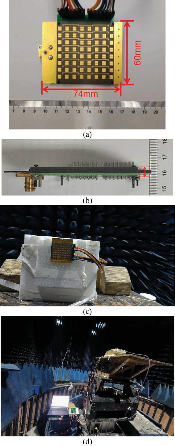
Figure 8: Antenna array under measurement: (a) prototype of designed antenna, (b) profile structure of the prototype, (c) measurement in the anechoic chamber and (d) test environment and test equipment.
III. FABRICATION AND MEASUREMENT
Based on the previous design, the designed principle prototype and antenna test environment are shown in Fig. 8. The overall size of the prototype is 74604 mm, and a stepped laminated design is adopted to meet the requirements of wiring and perforation process. The array is independently tuned by eight columns of liquid crystal phase shifters. The phase shifters are filled with VMLC-2101 liquid crystal with a thickness of 0.254 mm. The relevant parameters are , , and at normal temperature.
Table 1: Key parameters of the designed array antenna (mm)
| Lc_W | Lc_L | Ph_L | Ph_dL | At_L | At_W | G | h |
| 10.6 | 5.2 | 5.6 | 1.2 | 3.1 | 2.8 | 0.21 | 0.508 |
Table 2: Comparison with other phased array antenna
| Ref. | Tuning | Element | Peak | Range | Size of | Operating | Bandwidth |
| Material | Number | Gain (dBi) | Antenna (mm3) | Frequency (GHZ) | (%) | ||
| [1] | PIN | 14 | 9.3 | 58 | 35651.524 | 2.85 | 26 |
| [11] | LM | 14 | 8.3 | 38∘ | 57.2148 | 10 | 12 |
| [2] | PIN | 242 | 13.8 | 60∘ | 250501.881 | 14.8 | 6.7 |
| [8] | Varactor-diode | 44 | 8.1 | 25∘ | 70701.524 | 12 | 10 |
| [9] | CMOS | 14 | 17.6 | 32∘ | – | 16.5 | 16.4 |
| [12] | LC | 14 | 6.7 | 23∘ | 35502.5 | 35 | 5.1 |
| This Work | LC | 88 | 20.2 | 60∘ | 74604 | 27 | 7.4 |
The key dimensional parameters of the designed array antenna, corresponding to the labels in the structural diagrams, are summarized in Table 1. Different bias voltage groups are applied to the antenna, and the radiation signal of the standard antenna at the far field end is received and processed by using the antenna to be tested. Results of the far-field pattern parameters are obtained and saved, and the test results are shown in Fig. 9. The maximum gain of the antenna to be tested is 20.2 dBi. Attenuation is 1.23 dB at 30∘, 2.64 dB at 30∘, 4.48 dB at 60∘ and 4.63 dB at 60∘. A comparison of phased arrays fabricated by different methods is shown in Table 2.
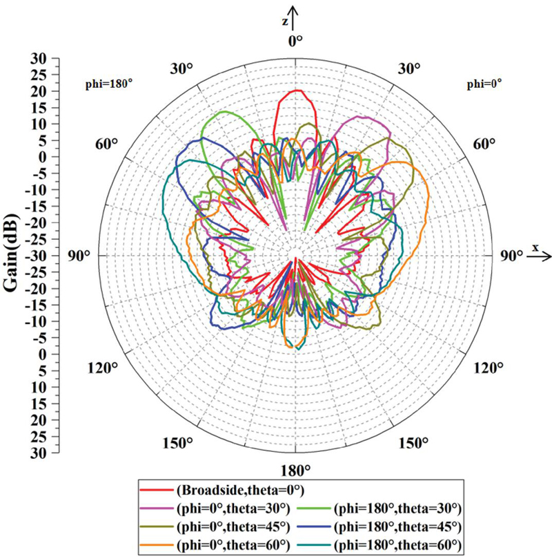
Figure 9: Test results of radiation patterns under different dielectric constants at the operating frequency.
Compared with the simulations, the test results of the prototype are asymmetrical and the gain of the beams are degraded to a certain extent. There are four main reasons to explain the discrepancy between the simulations and the tests. First, the antenna array is designed with a non-strictly symmetric structure, and the scanning beam is not strictly symmetrical due to the influence of the boundary conditions of the antenna unit during the scanning of E-plane beam. The second reason is that the liquid crystal molecular direction is affected by the time of applying bias voltage and the initial state, so it is difficult to achieve quantitative unification, and there are bubbles in the perfusion process leading to errors in the change of dielectric constant. The third reason is that the liquid crystal layer is too thin, resulting in uneven liquid crystal contact. By thickening the liquid crystal layer and re-matching the impedance, this effect can be reduced. The fourth reason is that, due to the high-frequency band and small size, even slight deviations in the processed metal via holes and PCB lamination can cause impedance variations, leading to losses.
IV. CONCLUSION
In this paper, we present a design method for a large-angle beam scanning antenna based on liquid crystal. The antenna achieves single-frequency beam scanning. An innovative design structure of liquid crystal antenna is proposed to enable wide-angle beam control. The test results show that the antenna can achieve 60∘ beam scanning at 27 GHz and gain is higher than 20 dBi, which verifies that the design of the antenna meets the requirements for large-angle beam scanning and supports the theory of liquid crystal reconfiguration.
ACKNOWLEDGMENT
This work was supported by the Sichuan Science and Technology Program (2023ZDZX0015); Science and Technology Projects of Chengdu (2023-JB00-00019-GX); Key Research and Development Program of Guangxi (AB25069115).
REFERENCES
[1] H. Xing, K. Zhang, M. Wang, C. Fan, H. Zheng, and E. Li, “Lower sidelobe phased array based on pattern reconfigurable elements,” International Journal of RF and Microwave Computer-Aided Engineering, vol. 32, no. 7, p. e23171, 2022.
[2] X. Li, H. Q. Yang, R. W. Shao, F. Zhai, G. B. Liu, Z. X. Wang, H. F. Gao, G. Fan, J. W. Wu, Q. Cheng, and T.-J. Cui, “Low cost and high performance 5-bit programmable phased array antenna at Ku-band,” PIER, vol. 175, pp. 29–43, 2022.
[3] S. Xu, K. Wu, Q. Zhou, S. Liao, and Q. Xue, “Low-profile conical beam array antenna based on concentric annular planar inverted-F antenna elements,” IEEE Antennas and Wireless Propagation Letters, vol. 22, no. 7, pp. 1562–1566, July 2023.
[4] B. Xi, Y. Xiao, S. Tan, F. Yang, and Z. Chen, “2-Bit wideband electronically controlled reconfigurable phased array with wide-angle beam-scanning capacity,” IEEE Transactions on Antennas and Propagation, vol. 71, no. 5, pp. 4128–4137, May 2023.
[5] H. Yu, P. Li, J. Su, Z. Li, S. Xu, and F. Yang, “Reconfigurable bidirectional beam-steering aperture with transmitarray, reflectarray, and transmit-reflect-array modes switching,” IEEE Transactions on Antennas and Propagation, vol. 71, no. 1, pp. 581–595, Jan. 2023.
[6] X. Cao, C. Deng, Y. Yin, Y. Hao, and K. Sarabandi, “1-Bit reconfigurable transmit- and reflect-array antenna using patch-ground-patch structure,” IEEE Antennas and Wireless Propagation Letters, vol. 23, no. 1, pp. 434–438, Jan. 2024.
[7] I. Syrytsin, S. Zhang, G. F. Pedersen, and A. S. Morris, “Compact quad-mode planar phased array with wideband for 5G mobile terminals,” IEEE Transactions on Antennas and Propagation, vol. 66, no. 9, pp. 4648–4657, Sep. 2018.
[8] M. Nikfalazar, M. Sazegar, A. Mehmood, A. Wiens, A. Friederich, H. Maune, J. R. Binder, and R. Jakoby. “Two-dimensional beam-steering phased-array antenna with compact tunable phase shifter based on BST thick films,” IEEE Antennas and Wireless Propagation Letters, vol. 16, pp. 585–588, 2017.
[9] Q. Zhang, C. Zhao, X. Zhang, Y. Wu, Y. Yu, and H. Liu, “A cost-effective Ku-band phased array in package integrating multi-independent CMOS transceivers with on-chip antennas,” IEEE Microwave and Wireless Technology Letters, vol. 33, no. 10, pp. 1486–1489, Oct. 2023.
[10] H. Jeon and K. W. Kobayashi, “A high linearity +44.5-dBm IP3C-Band 6-Bit digital phase shifter using SOI technology for phased array applications,” IEEE Microwave and Wireless Components Letters, vol. 29, no. 11, pp. 733–736, Nov. 2019.
[11] S. Alkaraki, Q.-W. Lin, J. R. Kelly, Z. Wang, and H. Wong, “Phased array antenna system enabled by liquid metal phase shifters,” IEEE Access, vol. 11, pp. 96987–97000, 2023.
[12] X. Y. Li, D. Jiang, J. Liu, and M. S. Tong, “A Ka-band multilayer beaming-scanning antenna using liquid crystals,” IEEE Antennas and Wireless Propagation Letters, vol. 21, no. 1, pp. 44–48, Jan. 2022.
[13] S. Ma, S.-Q. Zhang, L.-Q. Ma, F.-Y. Meng, D. Erni, L. Zhu, J.-H. Fu, and Q. Wu, “Compact planar array antenna with electrically beam steering from backfire to endfire based on liquid crystal,” IET Microwaves, Antennas & Propagation, vol. 12, no. 7, pp. 1140–1146, 2018.
[14] O. H. Karabey, A. Gaebler, S. Strunck, and R. Jakoby, “A 2-D electronically steered phased-array antenna with 22 elements in LC display technology,” IEEE Transactions on Microwave Theory and Techniques, vol. 60, no. 5, pp. 1297–1306, May 2012.
[15] O. H. Karabey, A. Mehmood, M. Ayluctarhan, H. Braun, M. Letz, and R. Jakoby, “Liquid crystal based phased array antenna with improved beam scanning capability,” Electronics Letters, vol. 50, no. 6, pp. 426–428, 2014.
BIOGRAPHIES

Wei Hu is a doctoral candidate of electronic information in Information and Communication Engineering, University of Electronic Science and Technology of China. He has a master’s degree in communication and information system from Sichuan University. His main research direction is intelligent sensing and information system, microwave reconfigurable devices and systems, and broadband reconfigurable array antenna.

Di Jiang is Professor of Information and Communication Engineering, University of Electronic Science and Technology of China. He is mainly engaged in broadband reconfigurable microwave devices, array antennas, and liquid crystal array antennas.

Jiahao Zhao is a graduate student majoring in Electronic Information at the University of Electronic Science and Technology of China, with his main research directions focusing on RCS reduction metasurfaces and array antennas.

Chenqi Zhang is a graduate student of Information and Communication Engineering, from the University of Electronic Science and Technology of China. His main research direction is phased array antenna and holographic antenna.

Guhaolan Zhao is a graduate student majoring in Electronic Information at the University of Electronic Science and Technology of China. His research interests include reconfigurable antennas and antenna arrays.

Jiacheng Zhao is a graduate student majoring in Information and Communication Engineering at the University of Electronic Science and Technology of China. His research focuses on metasurfaces for RCS reduction.

Bo Yan is a professor of Information and Communication Engineering at the University of Electronic Science and Technology of China. Her current research interests lie in embedded system, FPGA/ASIC design, and AI for the Internet of Things (AIoT).

Chuanpei Xu received her Ph.D. degree from Xidian University, China, in 2006. She is currently a professor of Instrument Science and Technology at Guilin University of Electronic Science and Technology in Guangxi, China. Her current research focuses on integrated circuit testing, automatic test and control systems, microfluidics, and biosensors.

Guofu Wang was born in Pingdingshan, China, in 1977. He received the M.S. and Ph.D. degrees in signal and information processing from the Chinese Academy of Sciences in 2005 and 2007, respectively. Since 2017, he has been a Professor with the School of Electrical and Information Engineering, Guangxi University of Technology. His main research interests include adaptive signal processing and image processing. He has a rich research experience in the development of key technologies of photoelectric countermeasure turntables.
ACES JOURNAL, Vol. 40, No. 11, 1102–1108
DOI: 10.13052/2025.ACES.J.401106
© 2025 River Publishers