A Novel Design for Four-port Metamaterial SRR-loaded MIMO Antenna for 5G and Wireless Communication Applications
M. Rajakumar and M. Meena
Department of Electronics and Communication Engineering
Vels Institute of Science, Technology & Advanced Studies, Tamil Nadu 600117, India
raj998779@gmail.com, meena.se@velsuniv.ac.in
Submitted On: July 12, 2024; Accepted On: December 15, 2024
ABSTRACT
In this paper, a new high-polarization metamaterial structure design for a multiple-input, multiple-output (MIMO) antenna with robust isolation is introduced. The antenna design satisfies the requirements of C-band and S-band wireless communication networks up to sub-6 GHz 5G applications. The novel design of the antenna gets three frequency bands—5.8 GHz, 3.4 GHz, and 2.57 GHz—to be taken into consideration. After the integration of metamaterial components and without use of any further decoupling techniques, high isolation of more than 20 dB is achieved. By suppressing the propagation of surface waves, low-band resonators can reduce the mutual coupling between two higher bands. Ultimately, the initial coupling is canceled out using a split-ring resonator (SRR) to minimize coupling in the low band. The stated MIMO antenna has a maximum return loss of -13, -18, and -21 dB and a mutual coupling of -13, -18, and -21 dB. It covers the 2.5, 3.4, and 5.8 GHz bands, which are used for WLAN, LTE, and 5G. Within acceptable bounds, the envelope correlation coefficient is less than 0.01 and the total active reflection coefficient is less than -10 dB. The performance of MIMO antennas is observed practically and reported.
Index Terms: 5G, meta material structure, MIMO design, unit cell, wireless applications.
I. INTRODUCTION
Multiband antennas capable of operating in many frequency bands are becoming increasingly important as mobile communication networks such as WLAN and WiMAX evolve. To make it easier to integrate the antennas with other system parts, they should also have a broad bandwidth and low profile. One effective way to meet the prior requirements is to use printed antennas. Various methods have been explored in the literature to accomplish multi-band properties. In order to produce various resonance frequencies, the most common method involves acting on the radiating element by etching holes or adding conducting strips [1–4]. The metamaterials utilized significantly lessen multi-antenna coupling. The introduction of these materials, known as split-ring resonators (SRR), has boosted S parameters, transmission effectiveness, diversity gain (DG), radiation characteristics, and envelope correlation coefficients (ECC) along the antenna patch plane [5–6].
Low radiative losses show that the separation between the two patch antennas may be increased by up to 20 dB without affecting the impedance bandwidth [6–8]. To meet the demand for multiple frequency bands, a number of strategies have been employed in the literature to produce dual-band or multi-band antennas, including a novel antenna constructed from metamaterial and with a spiral structure to act as a complementary SRR [9–12].
If the multiple-input, multiple-output (MIMO) only functions in one frequency band, it will be unable to fully utilize its inherent benefits and will squander frequency band resources. As a result, one of the fundamental technological problems confronting current wireless terminals and systems is developing an antenna for wireless applications that can handle dual-band or multi-band operations while maintaining acceptable performance [13–14].
The literature has also reported on a number of other MIMO antenna technologies for use in 5G smart phone applications. When it comes to channel capacity, ECC, and isolation, these systems excel. Many strategies, including spatial diversity, can be used to improve isolation between antenna sections [15–16]. Every antenna part must be tiny, well decoupled, and positioned on the phone (PCB or rim) with care. The suggested antenna material carries effectively on a lossy fr-4 substrate. In MIMO systems, proper port fielding and decoupling are required in order to provide uncorrelated channels. For a smooth integration with the increasing popularity of 5G connections, 5G devices must make room for 2G, 3G, and 4G MIMO/diversity antennas [17–18].
II. ANTENNA STRUCTURE AND DESIGN
The dimensions of the proposed antenna’s rectangular array are 70 65 mm (width length). It is intended to be used as a tri-band MIMO antenna. Thus, a 4-port MIMO antenna with an SRR construction is designed. The 1:7 metamaterial SRR is meant to enhance the MIMO system’s performance. The outer and inner rings are positioned between the MIMO antennas after achieving lower coupling loss.
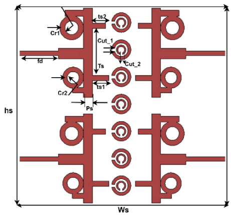
Figure 1: Proposed antenna structure.
The suggested antenna is made using a cheap FR-4 substrate that has a 1.6 mm dielectric constant (r 4.3). To build and optimize the suggested antenna construction, EM Simulator CST Studio Suite was utilized. In Fig. 1, the antenna diagram is displayed.
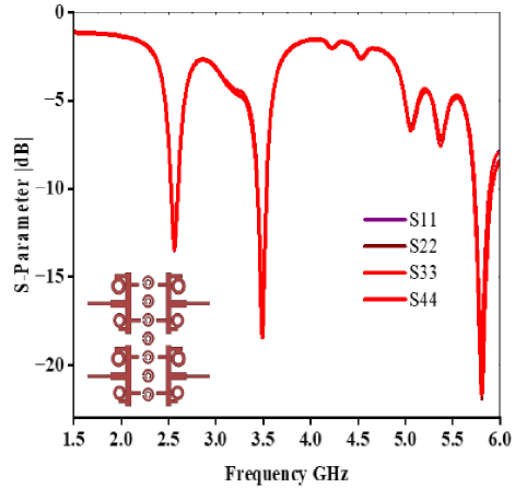
Figure 2: Reflection coefficient of four antennas.
Figure 2 shows that simulated reflection coefficients perform the highest return loss and radiate 90% of the power with a combination of metamaterial structure. Two concentric metallic rings engraved on a dielectric substrate in the form of a circle or square make up the SRR.
A. MIMO antenna design
In MIMO systems, contact between the antenna components via surface and space waves creates mutual coupling. As little as -10 dB is the reported gap between MIMO components 1 and 4. The high interaction between antennas 1 and 3 in space and surface waves is the reason for this poor isolation. The suggested MIMO system achieves a maximum gain of 4.4 dBi. The isolation and gain of the MIMO antenna must be improved to reduce the decoupling technique. Two metallic rings that are concentric on the dielectric substrate and etched in the shape of a circle or square make up the SRR. Their opposite ends are divided or have gaps. The MIMO antenna ECC measures the channel correlation between the antennas. The channel capacitance of a MIMO antenna increases the performance of the 4-port antenna as broad-band applications by providing strong mutual coupling between the antennas. The MIMO antenna channel capacitance of M and N Rx and Tx is:
| (1) |
The equation for a highly efficient and lossless antenna is based on channel capacitance c and S parameters.
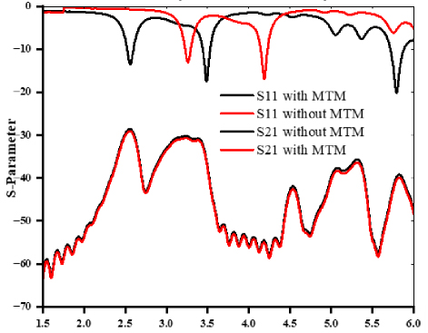
Figure 3: Transmission coefficient S and reflection coefficient S.
Figure 3 illustrates how the coupled power between two adjacent components is measured using the antenna isolation’s reflection coefficient (|S21|). A low-level matched load terminates the antenna output, and S11 is the input reflection coefficient. Forward transmission (from port 1 to port 2), reverse transmission (from port 2 to port 1), and output reflection coefficient (S22) are represented as S21, S21, and S12,respectively.
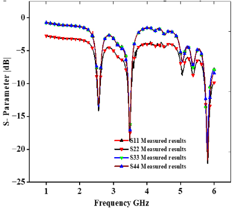
Figure 4: Reflection coefficient without metamaterial.
Figure 4 shows the reflection coefficients (S11 and S22) that were calculated and measured. With and without metamaterial structure, the planned MIMO systems show similar -15 dB impedance bandwidths. The 5G sub-6 GHz NR bands are still sufficiently covered, notwithstanding a little operational frequency modification brought on by metamaterial effects. After employing the metamaterial, the measured impedance for the originally intended MIMO antenna is BW 2.57 GHz (2.5-5.8 GHz).
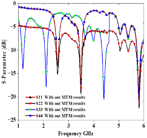
Figure 5: Refection coefficient with metamaterial (MTM).
Figure 5 shows the simulation results of the reflection coefficientwithout using metamaterial.
The integration of unit cell design into a MIMO system improves the isolation between the antennas. The effects of near-field coupling between the antennas are lessened when the proposed metamaterial is positioned close to the MIMO system, as seen in the isolation plots in Fig. 6. In the 5G NR bands, isolation between the opposing antennas (S12/S21) and the nearby antennas (S31/S41) increases by at least 3.5 dB. Maximum volume is less than 20 decibels.
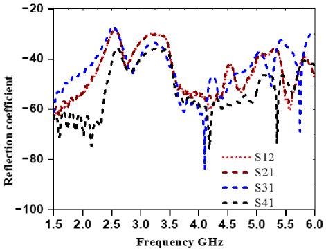
Figure 6: Transmission coefficients.
III. UNIT CELL DESIGN
Since the primary goal of the metamaterial design is to access wideband 5G spectrums, the suggested structure’s anticipated beginning dimensions are chosen to be at the frequency of 2.57 GHz, 3.5 GHz, and 5.8 GHz. At the intended frequencies of 2.57 to 5.8 GHz, the compact unit cell size (L) of 14 mm indicates Lu L/6.52 (see Table 1). This is sufficiently tiny to meet the metamaterial sub-wavelength criterion, enabling the achievement of the metamaterial effective response.
Figure 7 shows that the unit cell design substrate is twenty micrometers thick on both sides. Characterizing materials in the low-GHz spectrum is another objective of the investigation. Because of this, the SRR dimensions are thought to have measurement applications at frequencies close to 6 GHz. In this instance, the exterior ring’s length is l 20 mm, the gap’s width is g 1.5 mm, the rings’ width is w 20 mm, and the distance between them is c 1.5 mm. The geometrical layout of the SRR cell is displayed in Fig. 7, showing the low-cost, accessible proposed antenna aim of this project. With a dissipation factor of around 0.02 and a relative permittivity of r 4.4, we select a FR-4 substrate thus. The copper metallic substrate has a thickness of 1.6 mm.
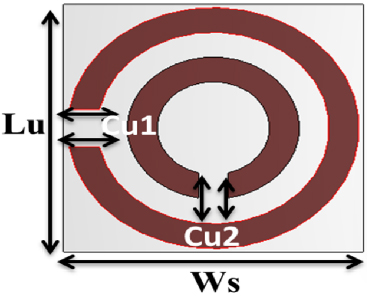
Figure 7: SRR unit cell design.
| S.No | Parameter | Value |
| 1 | Lu | 20 mm |
| 2 | Ws | 20 mm |
| 3 | Cut_1 | 1.5 mm |
| 4 | Cut_2 | 1.5 mm |
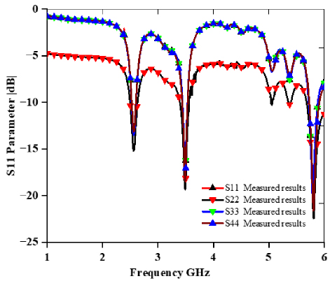
Figure 8: Reflection coefficient measured results.
A novel resonator with a modest size of 0.11min 0.02min at 3.4 GHz is produced utilizing 1.6 mm height low-cost FR-4 printed material (r 4.3 and tan 0.025). Figure 8 depicts the optimized unit cell geometry, which consists of two linked circle-shaped complementary split rings enclosed by double rings. Figure 8 depicts metamaterial reflector design specs, an enlarged image of a unit cell, and a sneak peek at the finished prototype. An adaptive tetrahedral mesh-based frequency domain solution is used on the EM simulator platform, CST Studio Suite, to analyze the unit cell. During the simulation process, the electric and magnetic fields are parallel to the unit cell structure.
The produced MMR confirms the epsilon negative (ENG) and mu-near-zero (MNZ) properties by displaying a near-zero positive permeability value (actual) over the indicated antenna operating spectrum. This material’s near-zero characteristics reduce the near-field coupling between magnetic and electric fields. The suggested antenna 44 compact design meets the condition modeling and measured results of the metamaterial structure employing a MIMO antenna.
In terms of technological merit, this approach has the following advantages over previous mutual decoupling techniques applied to MIMO antennas. The technique of integrating the SRR with metamaterial is proposed in this paper, wherein a circle stub design of structure operating at 2.57, 3.4, and 5.8 GHz is initially investigated, and then it is transformed into a metamaterial substance to further identify its mutual decoupling ability (see Table 2).
Table 2: Isolation from other antennas
| Ref. | Size | Freq. Band (GHz) | Isolation (dB) |
| [1] | 3535 | 45629 | 20 |
| [2] | 38.538.5 | 3.08-11.08 | 20 |
| [3] | 4848 | 2.5-12 | 15 |
| [6] | 3035 | 2.78-12.3 | - |
| [7] | 55100 | 1.85-11.9 | 17.2 |
| [8] | 2339.8 | 45628 | 20 |
| This work | 7065 | 2.57-5.8 | 23 |
An innovative SRR design that enhances impedance matching in MIMO antennas without utilizing any decoupling techniques suggests mutual coupling reduction.
Split-ring resonators optimize resonance frequency wireless applications with minimal radiative losses.
Reduced radiative losses of SRRs are a benefit. Their negative effective permeability at frequencies nearer the resonance frequency has led to the creation of left-handed media with a negative refractive index.
It is possible to convert this work into a low mutual coupling massive MIMO antenna since the edge-to-edge spacing between two selected antenna array parts can be as tiny as 0.0370.
IV. RESULTS AND DISCUSSION
For experimental examination, the constructed MIMO prototype is placed, as shown in Fig. 9, above the metamaterial reflector using two rings placed between the four antennas with 0.5 mm distance. During the reflection coefficient measuring technique, one to one antenna is activated. A 50 terminator is used to close the remaining two ports while the two MIMO system antennas are activated concurrently for the isolation measurement.
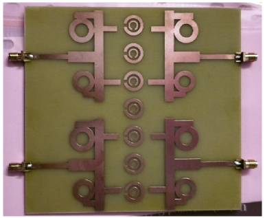
Figure 9: Fabrication of the antenna.
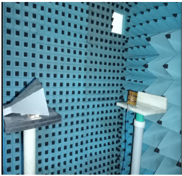
Figure 10: Antenna connected to VNA chamber.
Calculated and observed reflection coefficients (S11 and S22), with and without metamaterial structure, the planned MIMO systems show similar -15 dB impedance bandwidths. The 5G sub-6 GHz NR bands are still sufficiently covered, notwithstanding a little operational frequency modification brought on by metamaterial effects. After employing the metamaterial, the measured impedance for the originally intended MIMO antenna is BW 2.57 GHz (2.5-5.8 GHz). Simulated and observed isolation curves for the built-in MIMO antenna (with and without metamaterial), Fig. 10 shows antenna connected to VNA chamber to measure fabricated antenna.
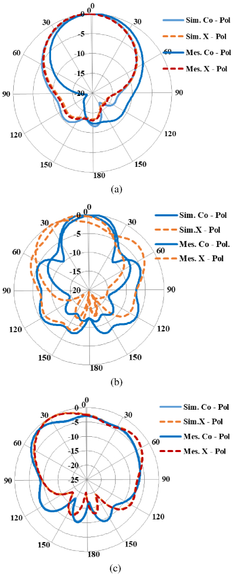
Figure 11: (a) 2.57 GHz, (b) 3.4 GHz, and (c) 5.8 GHz normalized co- and cross-polarized radiation pattern simulated and measured results.
Figure 11 shows the far-field results of the antenna as measured and simulated.
V. CONCLUSION
Here we present the four-port MIMO antenna for 5G and wireless applications and the created MIMO antenna, operating frequency ranges 2.57, 3.5 GHz to 5.8 GHz spectrum, covering the 5G NR n77/n78/n79 bands The wideband metamaterial reflector is added to the MIMO system to improve gain and isolation between two adjacent antenna radiators. The suggested antenna achieves a maximum gain of 8.1 dBi and an isolation of 20 dB, with a 4.2 dBi increase, demonstrating the metamaterial structural contribution to the specified MIMO system. After being made and tested, the suggested MIMO antenna experimental verification isgood.
REFERENCES
[1] L. C. Tsai, “Design of triple-band T-U-shaped CPW-FED slot antennas,” Microw. Opt. Technol. Lett., vol. 56, no. 4, pp. 844-848, Apr. 2014.
[2] J. Park, M. Jeong, N. Hussain, S. Rhee, P. Kim, and N. Kim, “Design and fabrication of triple-band folded dipole antenna for GPS/DCS/WLAN/WiMAX applications,” Microw. Opt. Technol. Lett., vol. 61, no. 5, pp. 1328-1332, 2019.
[3] P. Wang, G. J. Wen, Y. J. Huang, and Y. H. Sun, “Compact CPW fed planar monopole antenna with distinct triple bands for WiFi/WiMAX applications,” Electron. Lett., vol. 48, no. 7, pp. 357-359, Nov. 2012.
[4] Y.-D. Wang, J.-H. Lu, and H.-M. Hsiao, “Novel design of semi-circular slot antenna with triple-band operation for WLAN/WIMAX communication,” Microw. Opt. Technol. Lett., vol. 50, no. 6, pp. 1531-1534, June 2008.
[5] H. Sakli, C. Abdelhamid, C. Essid, and N. Sakli, “Metamaterial-based antenna performance enhancement for MIMO system applications,” IEEE Access, vol. 9, pp. 38546-38556, 2021.
[6] Z. Wang, W. Mu, M. Yang, and C. Li, “Design of compact multiband MIMO antenna based on ground neutralization line decoupling,” Applied Computational Electromagnetics Society (ACES) Journal, vol. 37, no. 6, June 2022.
[7] S. Luo, Y. Li, C.-Y.-D. Sim, Y. Xia, and X. Liu, “MIMO antenna based on metamaterial frequency selective surface,” Applied Computational Electromagnetics Society (ACES) Journal, vol. 36, no. 4, Apr. 2021.
[8] Y. Fan, J. Huang, T. Chang, and X. Liu, “A miniaturized four-element MIMO antenna with EBG for implantable medical devices,” Electromagn., RF and Microw. in Med. and Biol., vol. 2, no. 4, pp. 226-233, Dec. 2018.
[9] A. Iqbal, M. Al-Hasan, I. B. Mabrouk, and M. Nedil, “Scalp-implantable MIMO antenna for high-data-rate head implants,” IEEE Antennas Wireless Propag. Lett., vol. 20, no. 12, pp. 2529-2533, Dec. 2021.
[10] M. S. Singh, J. Ghosh, S. Ghosh, and A. Sarkhel, “Miniaturized dual-antenna system for implantable biotelemetry application,” IEEE Antennas and Wireless Propagation Letters, vol. 20, no. 8, pp. 1394-1398, May 2021.
[11] S. M. A. Shah, M. Zada, J. Nasir, O. Owais, A. Iqbal, and H. Yoo, “Miniaturized four-port MIMO implantable antenna for high-data rate wireless-capsule-endoscopy applications,” IEEE Trans. Antennas Propag., vol. 71, no. 4, pp. 3123-3133, Mar. 2023.
[12] A. Iqbal, M. Al-Hasan, I. B. Mabrouk, and M. Nedil, “A compact implantable MIMO antenna for high-data-rate biotelemetry applications,” IEEE Trans. Antennas Propag., vol. 70, no. 1, pp. 631-640, Jan. 2022.
[13] Z. Xia, H. Li, Z. Lee, S. Xiao, W. Shao, and X. Ding, “A wideband circularly polarized implantable patch antenna for ISM band biomedical applications,” IEEE Trans. Antennas Propag., vol. 68, no. 3, pp. 2399-2404, Mar. 2020.
[14] R. Luomaniemi, J.-M. Hannula, R. Kormilainen, A. Lehtovuori, and V. Viikari, “Unbroken metal rim MIMO antenna utilizing antenna clusters,” IEEE Antennas Wireless Propag. Lett., vol. 18, no. 6, pp. 1071-1075, June 2019.
[15] A. Burger. Nokia Claims 600 MHz LTE Equipment First [Online]. Available: www.telecompetitor.com/nokia-claims-600-mhz-lte-equipment-first/
[16] C. A. Wieczorek, “600MHz spectrum access systems and methods,” U.S. Patent 10 735 969 B2, 4 Aug. 2020.
[17] M. Rajakumar and M. Meena, “Compact tri-band loaded antenna for wireless communication and fifth generation applications,” Journal of Electrical Systems, vol. 20, no. 6s, 2024.
[18] S. C. D. Barrio, G. F. Pedersen, and A. S. Morris, “Tunable multiple-resonance antenna systems, devices, and methods for handsets operating in low LTE bands with wide duplex spacing,” U.S. Patent 10 541 475 B2, 21 Jan. 2020.
BIOGRAPHIES

M. Rajakumar is a research scholar at Vels University Chennai. His area of research ismetamaterial antenna forwireless applications. He completed his masters in VLSID design.

M. Meena is Associate Professor, Department of ECE, Vels University, Chennai. She has published 27 papers in National and International Journals. She has six patents in the area of wireless networks.
ACES JOURNAL, Vol. 39, No. 12, 1059–1065
doi: 10.13052/2024.ACES.J.391204
© 2024 River Publishers