High Gain Circularly Polarized Patch Antenna for Communications Between Cutting Tools and the Control Unit of Mining Equipment
Collin T. Kringlen, Atef Z. Elsherbeni, and Jamal Rostami
1Department of Electrical Engineering
Colorado School of Mines, Golden, CO, USA
collinkringlen@mines.edu, aelsherb@mines.edu
2Department of Mining Engineering
Colorado School of Mines, Golden, CO, USA
rostami@mines.edu
Submitted On: July 12, 2024; Accepted On: September 9, 2024
ABSTRACT
A 2.44 GHz high gain circular polarized (CP) patch antenna is designed, fabricated and tested for operation while mounted on a rotating cutting drum of a mining or excavation machine. This design incorporates a radiating element that is elevated above the ground plane to increase the antenna gain. The design utilizes a single feed source and a square truncated corner patch to produce CP radiation. The gain of the final design reached 9 dBi with a sufficiently CP axial ratio and more than 25 dB cross-polarization isolation. This system enables the data communication between the rock cutting tools installed on the machine and the unit to enable the remote monitoring of tool conditions as well as identification of the formations being mined.
Index Terms: Circular polarization, high gain, mining and excavation equipment, patch antenna.
I. INTRODUCTION
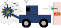
The mining industry is considered to be inherently dangerous, where workers are constantly exposed to risks such as confined spaces, dust, falling debris and heavy machinery [1, 2]. In response to the working conditions at various mining operations, there has been a trend in the mining and heavy civil construction industries towards the automation of excavation equipment, primarily aimed at minimizing operator presence in hazardous environments. This project seeks to advance this mission by developing a sensing system for various excavation units such as continuous miner (CM) or similar machines equipped with a pick cutter drum. Figure 1 shows an example of this machine. The sensing system, called “Smart Pick” or “Smart Bit” will provide the necessary data to operate the machine as if operatives were in close proximity to the machine. These data include cutting forces on the pick cutters which allows for monitoring bit wear and identification of the formation being mined. This is based on the measurement of cutting forces on the picks and analysis of signals using AI and ML algorithm for feature extraction to enable the machine to perform the above noted goals. Cutting force is combined with additional information such as drum rotation speed, thrust, rate of penetration, and drum torque/power to allow for identifying the type of rock being excavated. These data also have the potential to increase operational efficiency through the analysis of equipment wear data. Bit sensors, which are customized capacitive or piezoelectric load sensors, are installed between the pick cutter and the bit block mounted on the cutting drum.
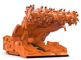
Figure 1: Picture of a continuous miner commonly used in mining of coal, trona, salt and soft rock types. Pick cutters are mounted on a drum to apply force and break the rock [14].
To transfer data from the rotating cutting drum to an onboard computer, control system or base remote station for analysis and real time monitoring of the working conditions, specialized antennas were developed to collect and transmit the data from the cutting tools to the control unit. The data transmission component should function in an environment that involves dust, presence of water or moisture in the air, impact by objects, and very high intensity vibration.
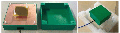
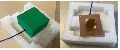
A block diagram of the system can be seen in Fig. 2. The yellow traces represent the signal output from each pick’s sensor. These data are then aggregated and preprocessed on the drum (orange box), and then transmitted by the designed data transmission system through the circular polarized (CP) antenna. Given the possibility of impact and interferences, a protective system had to be installed to prevent damage to the antenna by the impact of other objects. The protective system has to be designed in such way not to interfere or impede data transmission. As such, a special box was designed to offer protection against impact to the antennas. The transmitting and receiving antennas are placed inside the shown protective green box/cover.

Figure 2: Overall system configuration.
The antennas were required to have the following specifications for good communications: operation at 2.44 GHz, more than 6 dBi of gain, CP radiation and more than 25 dB isolation from the cross-polarized radiation. The unlicensed 2.44 GHz operation was chosen to be compatible with the rest of the communication hardware [3]. More than 6 dBi was selected to ensure a strong wireless link in the presence of debris, dust and water in the operational environment. This was determined through the Friis transmission equation. CP was necessary because the input data will be from the cutting tools on a rotating drum/cutterhead, thus putting the antennas at constantly changing orientations. Lastly, strong isolation of the cross polarized radiation is useful to reject any reflections produced in the underground environment [4].
Many different designs were reviewed to completely comprehend how a patch antenna might be optimized to this application [5–13]. Through this review, the elevation of the patch antenna above the ground plane stood out as a common strategy to develop high gain patch antennas.
II. L-SHAPED PATCH ANTENNA DESIGN
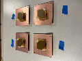
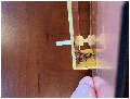
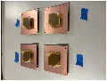
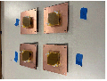
The current antenna design was initially based on the typical design outlined in [15, 16]. However, this published antenna design utilized copper sheets without any substrate backing for rigid support. The substrate backed antenna in Fig. 3 creates a more physically robust design which is required for the current application, given the harsh environment the antenna will be experiencing and the need for amplification of the signal. The substrate utilized was FR4 with 4.4 and electric conductivity 0.02. Furthermore, the antenna incorporates a two-piece patch: the main radiating element and a triangle vertical patch acting as a feed. The main radiating element is oriented parallel to the ground plane and utilizes a square, with truncated corner patch shape to produce CP radiation. This patch is elevated above the ground plane, leaving an air gap. The air gap acts as a low loss substrate, which contributes to the high gain in the proposed design. The small triangle patch, which is perpendicular to the ground plane, is used to feed the radiating element. Figure 4 shows the connection between the two patch components along with the coaxial center pin joint. The coaxial center pin is fixed directly at the bottom point of the triangle. This triangle acts as an efficient feeding method and contributes to the gain by directing more energy in the broadside direction and reducing losses that occur on the sides of the antenna. Lastly, a large ground plane is utilized to direct more energy in the broadside direction and further increase the gain. Right-hand and left-hand circularly polarized (RHCP and LHCP) antennas were designed and fabricated based on this design methodology and configuration.
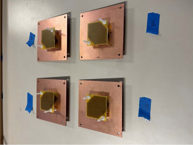
Figure 3: Fabricated LHCP L-shaped patch antenna.
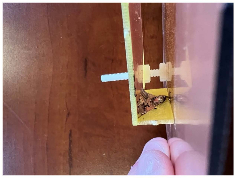
Figure 4: Inside view of solder joint of L-shaped patch.
A. Protective antenna covers
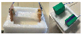
Given the violent, dusty, wet, underground environment, the antenna must have some functional protection. Thus, protective antenna covers were designed and fabricated. The box can also be sealed from air circulation to prevent gases from entering the area around the antenna, a measure that would be critical in getting pertinent certifications for the use of this system in gassy environments such as underground coal mines. The antenna utilizes a vertical coaxial feed as shown in Fig. 5. This required a two-piece cover, with a top and bottom portion, to act as enclosure. Furthermore, a 90-degree connector had to be used on the coaxial connection to allow for the design of a flat cover for a flush mounting solution on the drum. This cover is shown in Fig. 6.
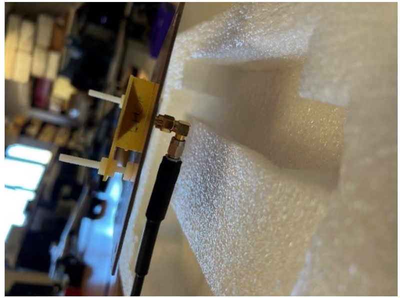
Figure 5: L-shaped patch antenna coaxial feed.
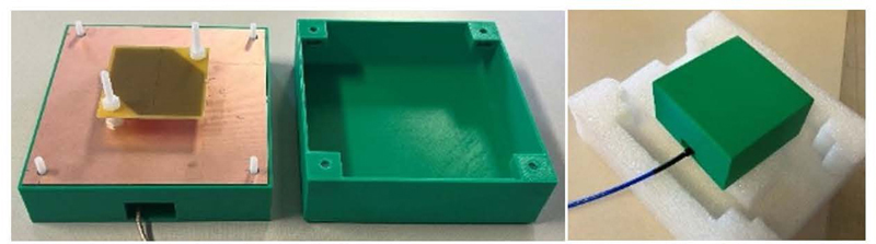
Figure 6: L-shaped patch protective antenna cover.
B. Simulations
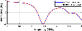
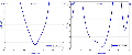
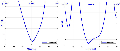
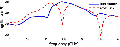
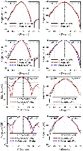
The simulations were conducted using the computational electromagnetic simulator (CEMS v5) which utilizes the finite difference time domain (FDTD) method [17, 18]. The RHCP and LHCP simulated models can be seen in Fig. 7. Figure 8 shows a dimensioned image of this design. The corresponding values for each dimension are shown in Table 1. These designs were optimized in the simulation tool for the requirements described in the introduction section. Various simulated results are shown in Figs. 9 to 13. Figure 9 shows input reflection of 20 dB at 2.44 GHz for the LHCP and RHCP simulations. Moving into the far field results, less than 1 dB AR is shown at broadside direction for both models in Figs. 10 and 11. Lastly, in Figs. 12 and 13, more than 25 dB cross-polarized isolation and 9 dB of gain are shown. Thus, the simulated model meets all requirements.

Figure 7: L-shaped patch LHCP and RHCP simulated antennas.
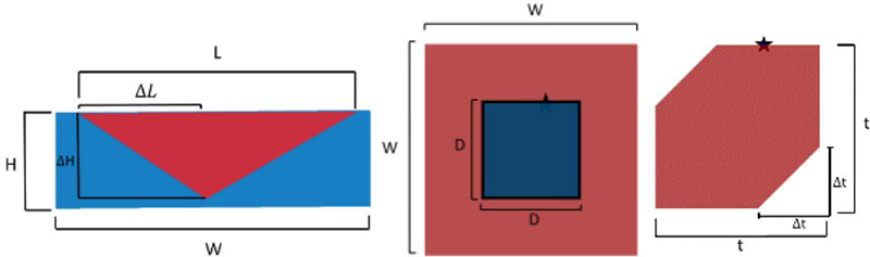
Figure 8: L-shaped patch antenna with dimensions defined.
Table 1: L-shaped patch dimension values
| Parameter | Dimension (mm) |
|---|---|
| W | 120 |
| D | 54.5 |
| T | 51.5 |
| t | 19.25 |
| H | 11 |
| H | 10 |
| L | 32.25 |
| centerL | 14.5 |
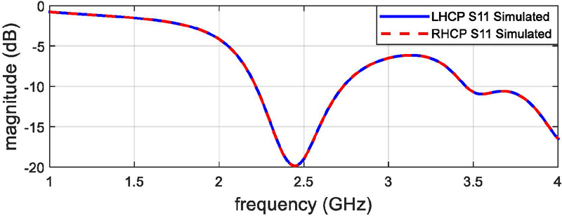
Figure 9: L-shaped patch LHCP and RHCP simulated S.
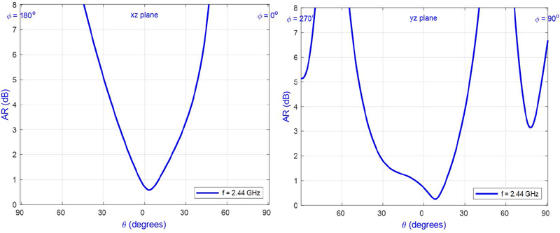
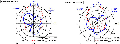
Figure 10: L-shaped patch LHCP AR in xz (left) and yz (right) planes.
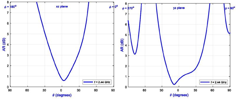
Figure 11: L-shaped patch RHCP AR in xz (left) and yz (right) planes.
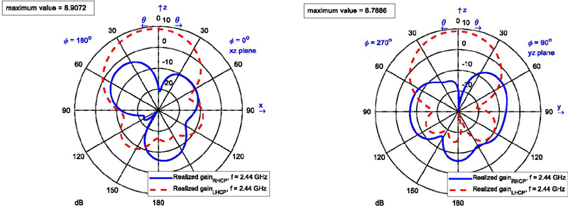
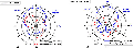
Figure 12: LHCP simulated radiation patterns with realized gain in xz (left) and yz (right) planes.
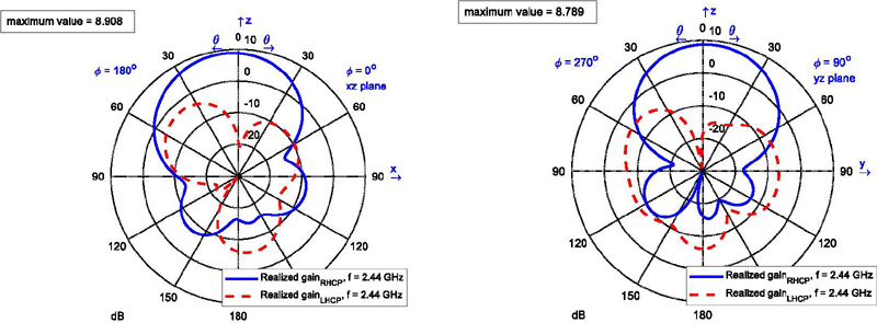
Figure 13: LHCP simulated radiation patterns with realized gain in xz (left) and yz (right) planes.
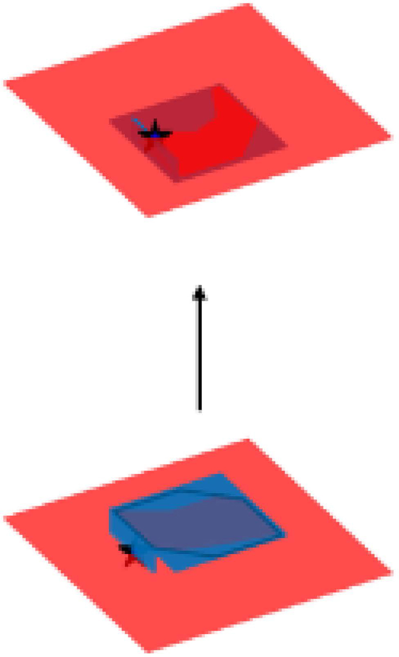
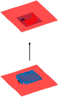
Figure 14: RHCP+RHCP antenna simulation (co-pol) configuration.
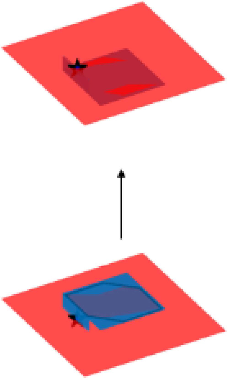
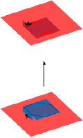
Figure 15: RHCP+LHCP antenna simulation (cross-pol) configuration.
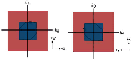
A separate set of simulations with two antennas were also conducted to collect simulated Sdata which will later be used to verify the antenna gain. The simulations were conducted with a co-pol antenna pair and a cross-pol antenna pair. Figures 14 and 15 show the simulation setups. The antennas are separated by 22 mm from ground plane to ground plane. The corresponding S results are shown in Fig. 16. As expected, in a line-of-sight transmission set up, the co-pol antennas are most efficient with 9.8 dB S when compared to the cross-pol S of 30 dB. The cross-pol antenna pair would be used in an application where a reflection of the wave between transmit and receive occurs, such as radar systems. At that time the S would be in the order of 9.8 dB.
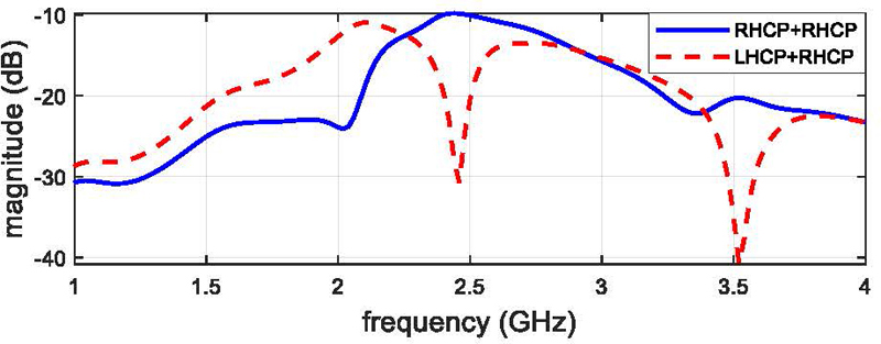
Figure 16: RHCP+RHCP (co-pol) and RHCP+LHCP (cross-pol) simulated S.
C. Fabrication and testing
Two RHCP and two LHCP antennas were fabricated as seen in Figs. 17 and 18. For brevity, one of each polarization will be shown with its corresponding measured results. The holes on all four corners of the antenna ground planes are for the plastic mounting screws of the antenna covers. These antennas were then tested, and results were compared with the simulateddata.
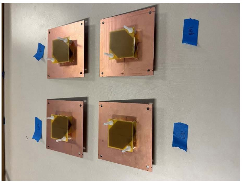
Figure 17: Fabricated LHCP L-shaped patch antenna.
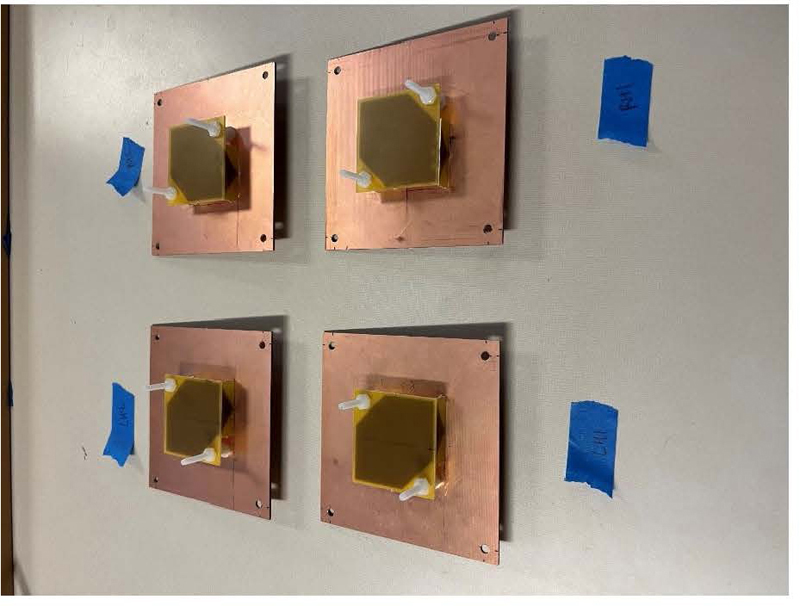
Figure 18: Fabricated RHCP L-shaped patch antenna.
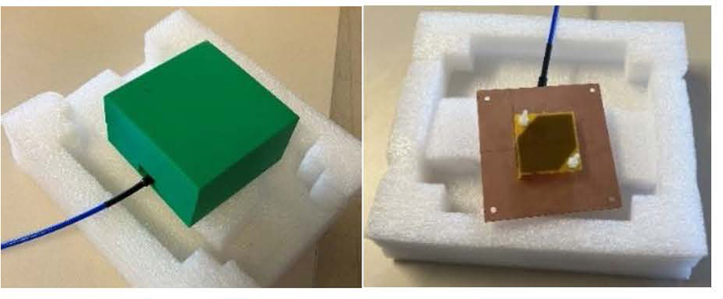
Figure 19: Covered and uncovered S measurement set up.
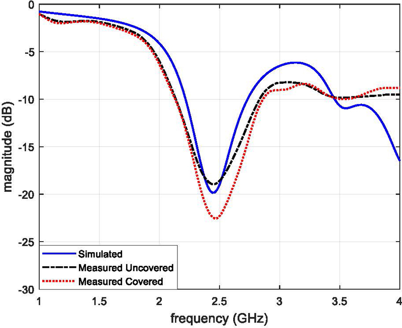
Figure 20: L-shaped patch antenna LHCP S.
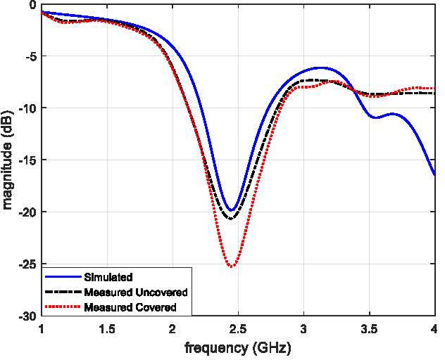
Figure 21: L-shaped patch antenna RHCP S.
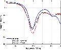
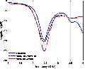
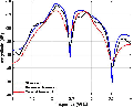
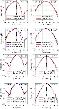
The antenna S was measured using a VNA where the covered and uncovered antennas are shown in Fig. 19. The data collected was then plotted with the simulated data to allow for a comprehensive comparison. These plots are shown in Figs. 20 and 21, where Fig. 20 shows a LHCP antenna Sand Fig. 21 shows a RHCP antenna S. Through these figures, a close correlation is seen between the three traces. The covered measurements appear to result in a better S when compared to the simulation and the uncovered measurement. Thus, the fabricated antennas preform as expected and the covers do not cause any negative effects on S.
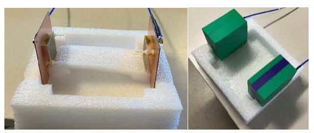
Figure 22: Covered and uncovered S measurement set up.
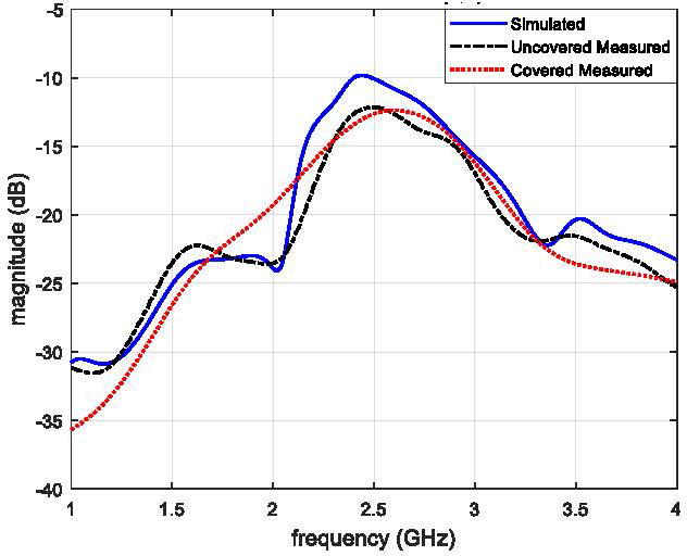
Figure 23: Co-pol antenna S measurement.
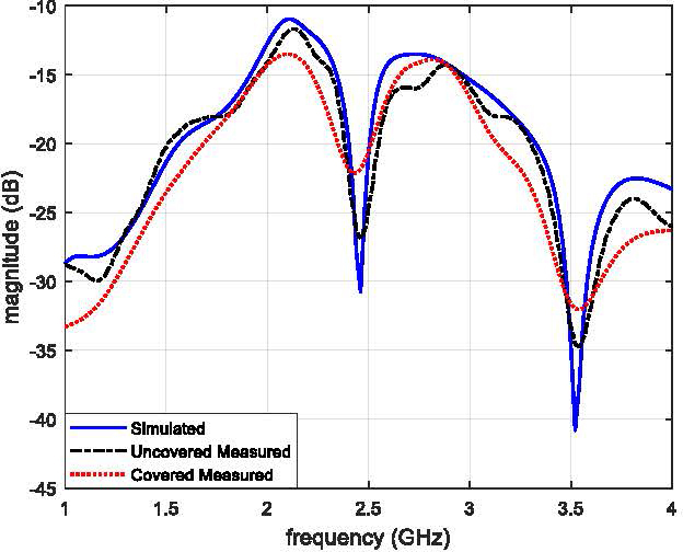
Figure 24: Cross-pol antenna S measurement.
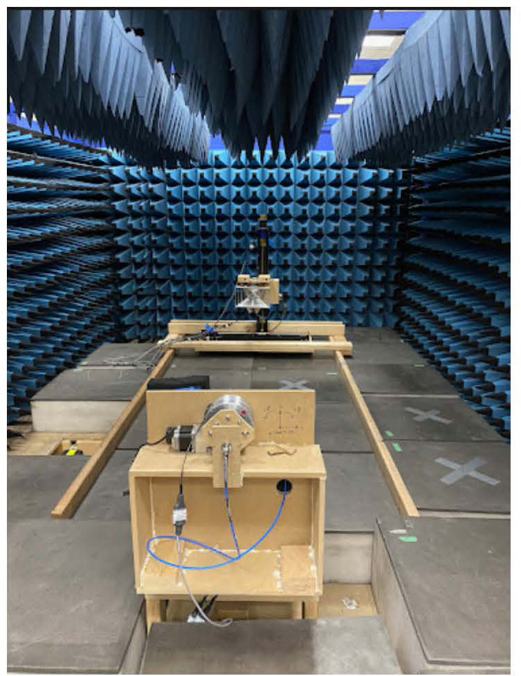
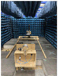
Figure 25: Anechoic chamber.
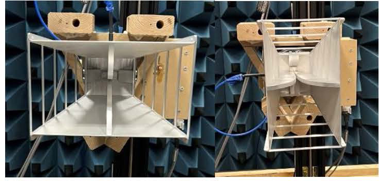
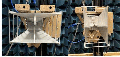
Figure 26: Anechoic chamber source horn in vertical (left) and horizontal (right) orientations from the view of the AUT.
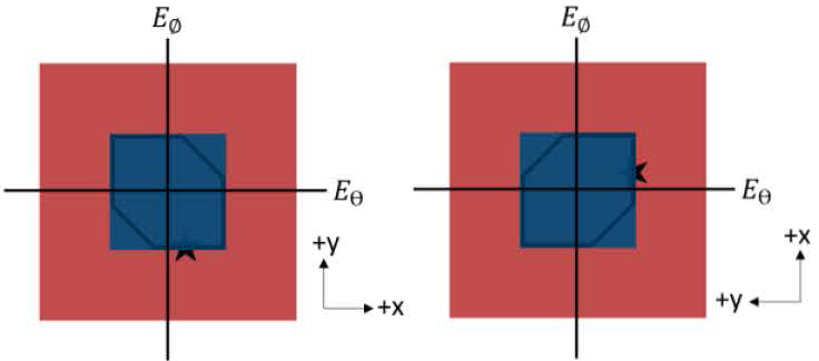
Figure 27: L-shaped patch E and E components for the LHCP antenna xz (right) and yz (left) planes.
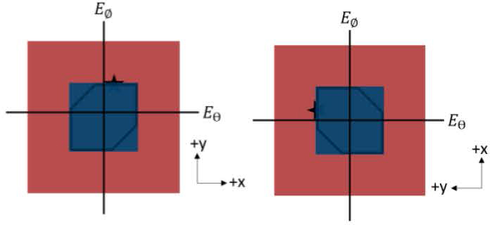
Figure 28: L-shaped patch E and E components for the RHCP antenna xz (right) and yz (left) planes.
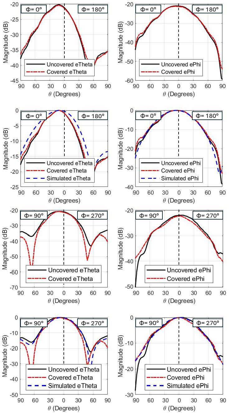
Figure 29: L-shaped patch LHCP normalized E and E plot for the xy (top) and yz (bottom) plane.
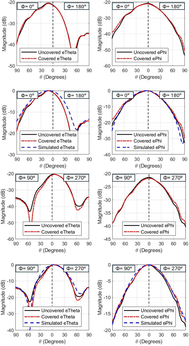
Figure 30: L-shaped patch RHCP normalized E and E plot for the xy (top) and yz (bottom) plane.
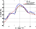
The S measurement set up for two of the LHCP antennas when they are covered and uncovered is shown in Fig. 22. This setup is used to measure the S to verify the simulated realized gain values shown in Figs. 12 and 13. Providing the simulated and measured S values at 2.44 GHz are close, it can be assumed that the gain of the fabricated antennas is close to that of the simulated value. The antennas are separated by 22 mm from ground plane to ground plane. Like the simulation, this test was conducted with co-pol antenna combinations and cross-pol antenna combinations. The results are plotted in Figs. 23 and 24. The covered and uncovered measured data nearly matched the simulated data in the co- and cross-pol cases. The measured data has more loss in the S measurement due to cable losses. Furthermore, the covered and uncovered data are similar. Overall, the covered and uncovered measured data shows the realized gain of the fabricated antennas is likely close to the simulated realized gain of 9 dB. Lastly, the data also shows that the covers have no negative effects on the ability of the antennas to transmit data.
Finally, radiation patterns of the fabricated antennas were measured in the Electrical Engineering Department’s anechoic chamber. The chamber is pictured in Fig. 25. The range utilizes a single ridge source horn as shown in Fig. 26. Thus, circular polarization measurements were not able to be taken in one sweep. As a workaround, the E and E components of each antenna were measured in the xz and yz planes. These are visualized in Figs. 27 and 28. The source horn ridges are simply aligned with whichever component is being measured and the antenna is swept from 90 to 90. These were then compared with the simulated E and E in both planes to confirm the fabricated antenna radiation patterns. These results are plotted in Figs. 29 and 30. Through close examination of the normalized data, it can be concluded that the simulation and measured results match very closely in both antennas for both planes. Thus, the radiation patterns and axial ratios of the fabricated antennas will be the same as the simulated models. Lastly, the results show the covers do not negatively affect the radiation patterns or axial ratio of the antennas.
III. CONCLUSION
The mining industry’s transition to automation allows enhancement in safety and operational efficiency amidst its inherent hazards. This project contributes to this transition by developing a sensing system for a typical rock excavation machine equipped with a pick cutter drum. The project seeks to enable remote operation of the machine by providing crucial real time operational data for efficient control and maneuvering of the machine as well as data on wear condition of the cutting tools. Through the integration of capacitive or piezoelectric load sensors into the cutter drum’s pick cutters and the development of high-gain antennas for data transmission, this project addresses key challenges in the transition toward automation, especially in underground mining operations. The L-shaped patch antenna design was optimized through simulations, fabricated and validated through testing. Additionally, the protective antenna covers ensure functional protection without compromising antenna performance. Lastly, the L-shaped patch antenna fulfills the stringent requirements by utilizing various gain increasing design aspects. This project sets a benchmark for the integration of wireless data transmission and load sensing technologies in the miningindustry.
ACKNOWLEDGMENT
This research was funded by NIOSH/CDC (contract number: 75D30119C05413, Improving Health and Safety of Mining Operations Through Development of the Smart Bit Concept for Automation of Mechanical Rock Excavation Units and Dust Mitigation).
REFERENCES
[1] National Safety Council, “Most dangerous industries,” Injury Facts 2023 [Online]. Available: https://injuryfacts.nsc.org/work/industry-incidence-rates/most-dangerous-industries/
[2] J. R. Bartels, C. C. Jobes, J. P. DuCarme, and T. J. Lutz, “Evaluation of work positions used by continuous miner operators in underground coal mines,” Proceedings of the Human Factors and Ergonomics Society Annual Meeting, vol. 53, no. 20, pp. 1622-1626, Oct. 2009.
[3] “Digi XBee 3 Zigbee 3 RF Module” [Online]. Available: https://www.digi.com/products/embedded-systems/digi-xbee/rf-modules/2-4-ghz-rf-modules/xbee3-zigbee-3
[4] “Circular Polarization” [Online]. Available: https://sciencedemonstrations.fas.harvard.edu/presentations/circular-polarization
[5] Y.-B. Tzeng, C.-W. Su, and C.-H. Lee, “Study of broadband CP patch antenna with its ground plane having an elevated portion,” in Asia-Pacific Microwave Conference Proceedings, Mar.2006.
[6] G. Yang, M. Ali, and R. Dougal, “A wideband circularly polarized microstrip patch antenna for 5-6 GHz wireless LAN applications,” Microwave and Optical Technology Letters, vol. 45, no. 4, pp. 279-285, Apr. 2005.
[7] Z. Wang, S. Fang, S. Fu, and S. Jia, “Single-fed broadband circularly polarized stacked patch antenna with horizontally meandered strip for universal UHF RFID applications,” IEEE Transactions on Microwave Theory and Techniques, vol. 59, no. 4, pp. 1066-1073, Apr. 2011.
[8] Y. Guo and D. C. H. Tan, “Wideband single-feed circularly polarized patch antenna with conical radiation pattern,” IEEE Antennas and Wireless Propagation Letters, vol. 8, pp. 924-926, July2009.
[9] Nasimuddin, K. P. Esselle, and A. K. Verma, “Wideband high-gain circularly polarized stacked microstrip antennas with an optimized C-type feed and a short horn,” IEEE Transactions on Antennas and Propagation, vol. 56, no. 2, pp. 578-581, Feb. 2008.
[10] S. Shekhawat, P. Sekra, D. Bhatnagar, V. K. Saxena, and J. S. Saini, “Stacked arrangement of rectangular microstrip patches for circularly polarized broadband performance,” IEEE Antennas and Wireless Propagation Letters, vol. 9, pp. 910-913, Sep. 2010.
[11] C. Chen, “A single-layer single-patch dual-polarized high-gain cross-shaped microstrip patch antenna,” IEEE Antennas and Wireless Propagation Letters, vol. 22, no. 10, pp. 2417-2421, Oct. 2023.
[12] Nasimuddin, K. P. Esselle, and A. K. Verma, “Wideband circularly polarized stacked microstrip antennas,” IEEE Antennas and Wireless Propagation Letters, vol. 6, pp. 21-24, July 2007.
[13] S. L. S. Yang, K. F. Lee, and A. A. Kishk, “Design and study of wideband single feed circularly polarized microstrip antennas,” Progress in Electromagnetics Research, vol. PIER, no. 80, pp. 45-61, Nov. 2008.
[14] “Joy12CM12,” Komatsu [Online]. Available: https://mining.komatsu/en-in/product-details/joy-12cm12
[15] F. S. Chang, K. L. Wong, and T.-W. Chiou, “Low-cost broadband circularly polarized patch antenna,” IEEE Transactions on Antennas and Propagation, vol. 51, no. 10, pp. 3006-3009, Oct. 2003.
[16] C.-W. Su, F.-S. Chang, and K.-L. Wong, “Broadband circularly polarized inverted-L patch antenna,” Microwave and Optical Technology Letters, vol. 38, no. 2, pp. 134-136, May 2003.
[17] A. Z. Elsherbeni, “FDTD Course Notes,” Department of Electrical Engineering, The University of Mississippi, MS, Spring 2001.
[18] V. Demir and A. Z. Elsherbeni, “Computational Electromagnetic Simulator,” Software Package version 5, veysdemir@gmail.com, Apr. 2024.
BIOGRAPHIES

Collin T. Kringlen obtained his M.S. degree from the Electrical Engineering Department, Colorado School of Mines in 2024. He is currently working with Lockheed Martin, in Colorado. His research interest includes computational electromagnetics, antenna design and phased array systems.

Atef Z. Elsherbeni received his Ph.D. degree in Electrical Engineering from Manitoba University, Winnipeg, Manitoba, Canada, in 1987. He started his engineering career as a part time Software and System Design Engineer from March 1980 to December 1982 at the Automated Data System Center, Cairo, Egypt. From January to August 1987, he was a Post-Doctoral Fellow at Manitoba University. Dr. Elsherbeni joined the faculty at the University of Mississippi in August 1987 as an Assistant Professor of Electrical Engineering and progressed to the full professor and the Associate Dean of the College of Engineering for Research and Graduate Programs. He then joined the Electrical Engineering and Computer Science (EECS) Department at Colorado School of Mines in August 2013. Dr. Elsherbeni is an IEEE Life Fellow and ACES Fellow. He is the Editor-in-Chief for Applied Computational Electromagnetics Society (ACES) Journal, and a past Associate Editor to the Radio Science journal. He was the Chair of the Engineering and Physics Division of the Mississippi Academy of Science, the Chair of the Educational Activity Committee for IEEE Region 3 Section, and the past President of ACES Society. He recently received the 2023 IEEE APS Harington-Mittra Award for his contribution to computational electromagnetics with hardware acceleration.

Jamal Rostami is the Haddon/Alacer Gold Endowed Chair, the Director of Earth Mechanics Institute (EMI), and Professor at Mining Engineering at Colorado School of Mines.
ACES JOURNAL, Vol. 39, No. 7, 642–650
doi: 10.13052/2024.ACES.J.390708
© 2024 River Publishers