Miniaturized Flat Archimedean Spiral Antenna
Miguel Fernandez-Munoz, Nerea Munoz-Mateos, Rocio Sanchez-Montero,Pablo Luis Lopez-Espi, Juan Antonio Martinez-Rojas, and Efren Diez-Jimenez
1Signal Theory and Communications Department, Mechanical Engineering Area
Universidad de Alcalá - Escuela Politécnica Superior, Alcalá de Henares 28805, Spain
miguel.fm@uah.es, efren.diez@uah.es
2Signal Theory and Communications Department, Radiation and Sensing Group
Universidad de Alcalá - Escuela Politécnica Superior, Alcalá de Henares 28805, Spain
nerea.munozm@edu.uah.es, rocio.sanchez@uah.es, pablo.lopez@uah.es, juanan.martinez@uah.es
Submitted On: July 23, 2024; Accepted On: December 4, 2024
ABSTRACT
This paper presents the design and tests of a miniaturized flat Archimedean spiral antenna. The antenna has two gold Archimedean spiral arms on the surface of a thick alumina cylinder. This cylindrical substrate has an outer diameter of 1.1 mm and a thickness of 0.52 mm. These reduced dimensions make the presented antenna at least an order of magnitude smaller than any previous planar Archimedean spiral antenna reported in the literature. This small antenna can be used for communication in small devices, wireless power transmission for implantable sensors, microrobots and other micro applications. Despite its reduced size, the antenna has a relatively low resonant frequency, which was measured at 4.9 GHz. The characteristic length of the antenna can be reported as only 0.018. The design and simulations of the fundamental parameters of the antenna are presented, showing a uniform radiation pattern. Also, the manufacturing process is described. Seven prototypes of the antenna have been manufactured and their reflection coefficient was measured. The tests showed good agreement with simulations. The repeatability of the measurements and the reliability of the fabrication process are demonstrated.
Index Terms: Antenna prototype, Archimedean spiral, finite element simulation (FEM), miniaturization.
I. INTRODUCTION
Spiral antennas are commonly used in low-frequency applications. These antennas achieve low resonant frequencies by extending their electric path over the entire surface of their substrates. They can have multiple morphologies that can be used depending on the requirements of the particular application.
Some of these antennas have circular [1, 2] or square spirals (meanders) [3, 4]. Concerning circular spirals, Archimedean spiral antennas are generally used because they have a wide bandwidth [5, 6]. Spiral architecture may be suitable for small array applications [7], which allows us to create omnidirectional antennas by connecting several of these spirals in arrays [8].
There are several articles related to improvements in Archimedean spiral antennas [9], for example in the optimization of the antenna substrate [10, 11]. The authors of [12] present a four-armed Archimedean spiral antenna that uses transmission lines to perform the necessary impedance transformation between the impedance of the spiral and the 50 port. In [13], a modified Archimedean spiral antenna without balun is presented. A frequency reconfigurable Archimedean spiral antenna is shown in [14]. The frequency reconfiguration is done by a pair of meandered slotlines. There is even work on Archimedean spiral antennas on conducting textile filaments [15] that operate in curved shapes. Some papers present research on low profile [16], compact [6, 8, 17, 18], or miniaturized [19, 20] Archimedean spiral antennas. However, these antennas are larger than several centimeters.
In this paper, the development of a millimeter-sized Archimedean spiral antenna is presented, achieving miniaturization while maintaining a low resonant frequency. The dimensions of the proposed antenna are at least one order of magnitude smaller than those found in the literature. Furthermore, the characteristic length of the antenna, which compares the resonant frequency with the larger dimension of each antenna, is at least one order of magnitude smaller, proving the significant miniaturization achieved.
Miniaturized antennas can replace larger antennas to perform the same function in a smaller volume, for example in communication devices, or to enable wireless communication in new areas such as microrobotics [21], micromagnetic coils [22, 23], or implantable medical devices [24, 25].
The resonant frequency of antennas usually decreases in inverse proportion to the antenna size [26, 27]. That is, the lower the frequency, the larger the antenna. This effect is one of the main difficulties in developing miniaturized antennas that can operate at low frequencies. However, having a low resonance frequency can be beneficial in some situations, such as in the development of antennas for intracorporeal applications. In these applications, the lower the resonance frequency, the lower the losses due to the absorption of electromagnetic energy in the human body.
Following this track, numerous studies have been published on miniaturized antennas of different morphologies, many of them with medical purposes, mainly patch-on-chip antennas [28–30] and helical antennas [31–33]. However, no Archimedean spiral antennas have been found with sizes in the same order as the one proposed in this paper.
This paper presents a patch antenna with Archimedean spirals of only 1.1 mm diameter and 0.52 mm height. Despite its small size, the antenna has a resonant frequency of 4.9 GHz. The design and simulations of the antenna are presented, as well as measurements of the reflection coefficient on fabricated prototypes. These measurements demonstrate high repeatability and accuracy of the prototypes.
II. ANTENNA DESIGN AND GEOMETRY DESCRIPTION
The antenna was designed specifically with small dimensions and low resonant frequency. The Archimedean spiral generated the following expression, with d being the diameter of the spiral, d the internal diameter, a the growth rate, and the angular position. By equating the arm width to the separation between arms, a self-complementary structure is achieved and, therefore, with real and constant impedance throughout the frequency:
| (1) |
Following the radiation theory developed by Kaiser about the Archimedean spirals of two arms [34], it can be deduced that the diameter the spiral will have when the currents of both arms are in phase will be:
| (2) |
Knowing the expression that relates frequency to wavelength based on the speed of light, it can be concluded that the diameter of the spiral is inversely proportional to the frequency, and can be calculated with the following expression:
| (3) |
Finally, it is worth mentioning that an improvement can be achieved in terms of gain value and beam width by adding a margin to the external radius due to the reduction of edge effect [27, 35]. However, this also entails an increase in the diameter of the spiral, so a compromise must be maintained between the size of the antenna and its minimum gain. The design equations for spiral antennas, therefore, are:
| (4) | |||
| (5) |
In addition, the dielectric constant of the substrate used must be considered, which modifies the diameter of the previous
| (6) |
The theoretical conclusions for frequencies between 1 and 5 GHz are shown in Fig. 1.
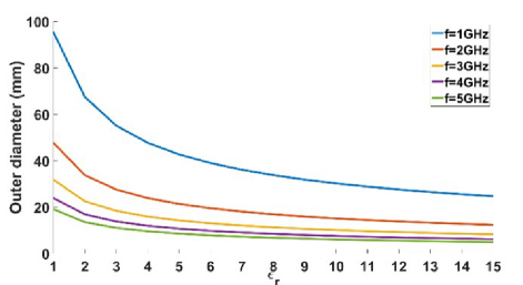
Figure 1: Theoretical resonant frequency of Archimedean spiral antennas as a function of their external diameter.
The geometric and resonant frequency requirements could not be reached by using standard Archimedean spiral antennas. Thus, the design process continued through FEM simulation, following an iterative process. Different constructions were analyzed, by varying the geometric parameters of the antenna, changing the arms shape, using substrates of different materials and changing the value of the port impedance. Finally, it was possible to simulate an antenna that met the geometric and resonant frequency requirements.
The final antenna design has a thin cylinder substrate of alumina with a relative permittivity () of 9.4 and dielectric loss tangent (tan) of 0.008. It has an outer diameter (S) of 1.1 mm, an inner diameter (S) of 0.18 mm, and a thickness (S) of 0.52 mm. The internal bore was created during fabrication to separate the arms of the antenna. To the authors’ knowledge, there are no studies in the literature on Archimedean spiral antennas of this size.
On the surface of the substrate there are two gold Archimedean spirals that form the two arms of the antenna. The arms are 0.02 mm wide (A) and 0.02 mm thick (A). Each arm has five turns separated by 0.02 mm (A).
In the center of the cylinder, on the same surface as the spirals, there is the antenna port. The port was defined at a position with a spacing (P) of 0.24 mm, rather than at the end of the arms, because the RF probe tip available in the laboratory required this minimum distance. The port width (P) is 0.05 mm. Figure 2 shows the geometric design of the antenna, and Table 1 gives the main dimensions of the antenna.
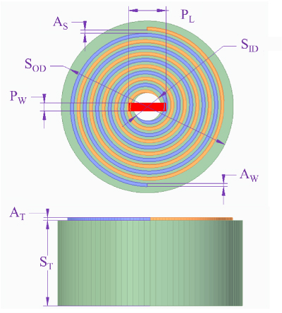
Figure 2: Antenna design with the main dimensions in millimeters.
Table 1: Main dimensions of the antenna
| Parameter | Nomenclature | Value (mm) |
| Port length | P | 0.24 |
| Port width | P | 0.05 |
| Substrate outer diameter | S | 1.1 |
| Substrate inner diameter | S | 0.18 |
| Substrate thickness | S | 0.5 |
| Arm width | A | 0.02 |
| Arm separation | A | 0.02 |
| Arm thickness | A | 0.02 |
III. ANTENNA FINITE ELEMENT MODEL SIMULATIONS
All antenna simulations were performed using the Ansys Electronics Desktop 2020 electromagnetic tool HFSS [36]. A model of the antenna was created according to the specifications described in the previous section. Simulations of the antenna as a single component were performed from 0 to 6.5 GHz, with a step of 0.1 GHz. The preliminary values of the impedance and resonant frequency of the antenna were used to narrow the frequency range of the simulation and improve accuracy. A time domain analysis with a discrete frequency sweep was performed from 3.5 to 5 GHz, with a step of 0.01 GHz, and a port with the same determined antenna impedance of 0.19 . The number of the solved elements is 127,841 and the mesh is based on hexahedrons.
The resonant frequency of the antenna was found to be 4.49 GHz, with a reflection coefficient (S11) of -14.41 dB [37]. The characteristic length of the antenna can be expressed as 0.016 (with the simulated resonant frequency). The reflection coefficient as a function of frequency is shown in Fig. 11. As defined by Harold Wheeler, this is an electrically small antenna because it occupies a volume of less than a radian sphere (0.16) [35]. It has an inherently narrow bandwidth, and it is expected to have a low gain. The expected theoretical gain of the antenna can be calculated from the radiation power factor formula for electrically small antennas:
| (7) |
With a radius of 0.008, a radiation power factor of 0.000127 and a gain -38.962 dBi are obtained.
A simulation was performed at the resonant frequency of 4.49 GHz to determine the gain and radiation pattern of the antenna. The 3D radiation pattern of the antenna is shown in Fig. 3, with a maximum simulated gain of -42.2 dBi, close to the calculated theoretical value. As expected, the antenna exhibits a symmetrical radiation pattern around the YZ plane. The maximum gain is achieved in the Z axis.
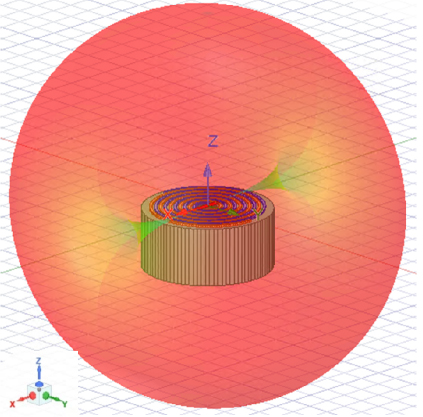
Figure 3: Simulated 3D radiation pattern of the antenna.
The radiation pattern of the two main orthogonal planes of the antenna is shown in Fig. 4. Figure 4 (a) shows the plane XY where the spiral is located. It is not symmetrical in either the Y-axis or the X-axis. The symmetry axes are rotated by with respect to the orthogonal vectors. According to this view, the radiation pattern has a maximum at phi and a null at phi. Figure 4 (b) is the plane XZ, the plane perpendicular to the surface of the spiral, which does not contain the ends of the arms. In this view, the radiation pattern presents a maximum at theta and a null at theta. The antenna has omnidirectional radiation at the plane YZ, the plane perpendicular to the surface of the spiral that contains the ends of the spiral arms.
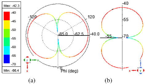
Figure 4: Simulated radiation pattern of the antenna: (a) plane XY and (b) plane XZ.
The polarization of the antenna, according to Fig. 5, is linear. The surface current distribution of electrically small antennas results in this type of polarization [9].
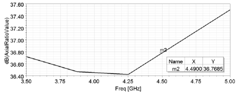
Figure 5: Simulated axial ratio of the antenna.
The simulated gain and efficiency of the antenna at different frequencies near the resonant frequency have also been simulated. They are shown in Figs. 6 and 7, respectively.
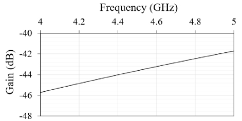
Figure 6: Simulated gain of the antenna.
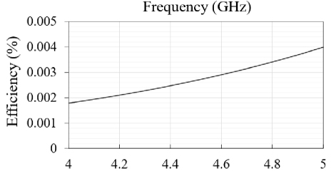
Figure 7: Simulated radiation efficiency of the antenna.
The curves of the simulated gain and the efficiency of the antenna are both linear, and they increase with frequency. The gain is low as explained before, and so is the radiation efficiency as a consequence of the low gain.
Subsequently, the equivalent circuit of the antenna was determined. It is important to calculate the necessary matching circuits for the final applications. The equivalent circuit of the antenna was calculated using the classical approximation of a resonant circuit. The behavior shown in the Smith chart leads to a series resonant circuit, as shown in Fig. 8.
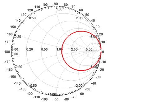
Figure 8: Simulated reflection coefficient of the antenna.
The resistance value is determined directly at the resonant frequency. For values of L and C, the 3 dB bandwidth was determined for impedance around the resonant frequency. The imaginary part of the antenna impedance, determined at f1 or f2, allows the L and C values to be calculated. This is shown in Table 2. As can be seen, the antenna impedance is very low, another reason to justify the lower value of the gain.
Table 2: Resonant frequency, bandwidth, and impedance values of the antenna
| F0 (GHz) | 3 dB Bandwidth Limits f2-f1 (GHz) | Z at f0 (ohm) |
| 4.49 | 4.505-4.475 | 0.19 |
Using the relations of input impedance, the following values listed in Table 3 are obtained.
Table 3: Impedance values of the equivalent circuit of the antenna
| R () | L (nH) | C (pF) |
| 0.19 | 1.1683 | 42.45 |
As the antenna impedance is not a standard value, it will need a matching circuit specifically designed for each application. Furthermore, this mismatch must be considered when comparing simulations with measurements. The electrical parameters of the measurement system will be introduced in the simulation to compare both in a more realistic way.
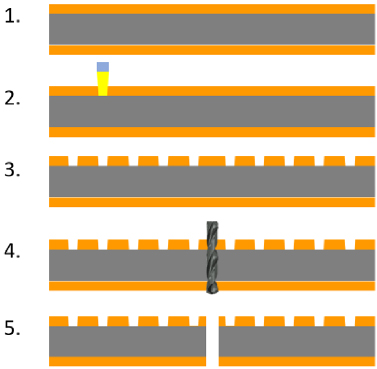
Figure 9: Archimedean spiral antenna manufacturing process: 0. initial substrate, 1. substrate with gold plating, 2. laser micromachining, 3. substrate with the micromachined spiral, 4. spiral center microdrilling, 5. manufactured Archimedean spiral antenna.
IV. ANTENNA MANUFACTURING
The Archimedean spiral antenna was then fabricated and tested. Seven prototypes of the Archimedean spiral antenna were fabricated in a clean room by microlaser machining according to the geometric design of section II. A diagram of the manufacturing process is shown in Fig. 9.
First, a 20 m thick layer of gold was chemically deposited on the surfaces of a 0.5 mm thick alumina sheet, from which a circle of 1.1 mm diameter was cut by micromilling (step 1). The spiral shape was laser micromachined onto the gold layer using an LPKF ProtoLaser U4 machine (steps 2 and 3). Finally, a microdrill was made in the center of the piece (step 4), finishing the manufacturing process (step 5). Figure 10 shows images of the fabricated prototypes.
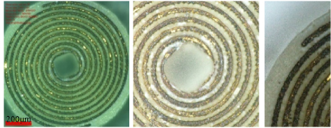
Figure 10: Prototypes under the microscope.
V. ANTENNA MEASUREMENT RESULTS
Reflection coefficients of the prototypes were measured using a Keysight ENA E5063A Vector Network Analyzer, a MPI TITAN RF TS200A probe, digital microscopes and travel translation stages for positioning the RF probe. The test setup is shown in Fig. 11 (a), the microprobe laying in the two ends of the spiral arms in Fig. 11 (b), and the tips of the differential microprobe in Fig. 11 (c).
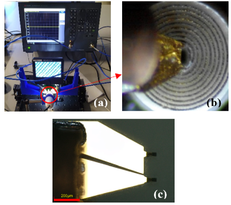
Figure 11: Reflection coefficient measurements setup.
The measured reflection coefficients of the seven prototypes compared to the simulations are shown in Fig. 12.
Table 4: Comparison of Archimedean spiral antennas
| Reference | Dimensions | Resonant Frequency (GHz) | Characteristic Length |
| [6] | 363620 mm | 2-6 | 0.240.240.13 |
| [8] | D72 mm | 1.2-3.6 | 0.29 |
| [16] | D9 mm | 8-16 | 0.24 |
| [17] | 37.537.520 mm | 1.99 | 0.250.250.13 |
| [18] | D23.2 mm | 4.6-9 | 0.356 |
| [19] | 19.7720.72 mm | 0.3-16 | 0.020.021 |
| [20] | 30303.048 mm | 2-6 | 0.20.20.02 |
| This work (simulated) | 1.11.10.537 mm | 4.49 | 0.016 |
| This work (measured) | 1.11.10.537 mm | 4.9 | 0.018 |

Figure 12: Open air simulated reflection coefficient, simulated reflection coefficient with capacitor, and measured reflection coefficients of each prototype.
As can be seen in Fig. 11, all measurements are accurate and repeatable, showing a resonant frequency at 4.9 GHz with a reflection coefficient of -12 dBi. The characteristic length of the antenna can be expressed as 0.018 (with the measured resonant frequency).
There is a difference between the simulated and the measured resonant frequency, which is a consequence of the capacitive effect caused by the RF probe. The RF probe was calibrated with the MPI calibration substrate AC-3 prior to testing. This difference is not a calibration error, but an effect caused by the probe due to its larger size compared to the antennas.
A parametric simulation was performed including a capacitor to model the effect of the RF probe. With a capacitor of 8.9 pF the resonant frequency was shifted to 5.7 GHz, shown in Fig. 11. The remaining difference between the two resonant frequencies can be attributed to be differences in the properties of the simulated material and the actual substrate, and differences in the final dimensions of the prototypes due to the tolerances of the manufacturing process.
Regarding the studies of Archimedean spiral antennas reported in the literature, they all have dimensions at least one order of magnitude larger than the one presented in this paper. Furthermore, the characteristic length of the antenna, which compares the resonant frequency with the larger dimension of each antenna, is at least one order of magnitude smaller, proving the great miniaturization achieved. The only Archimedean spiral antenna with a similar characteristic length is the one presented in [19], but it has a surface area more than 300 times larger. Table 4 compares the resonant frequency and dimensions of the developed Archimedean spiral antenna with those of the publications analyzed.
VI. CONCLUSION
In this paper, an ultra-miniaturized planar Archimedean spiral antenna is proposed. The antenna has a diameter of 1.1 mm and a thickness of 0.52 mm, which is at least an order of magnitude less than the Archimedean antennas found in the literature. The proposed antenna could be used in telecommunication devices to perform the same function at a smaller volume, or in cutting-edge applications such as communication microsystems, microrobotics, or implantable medical microdevices. The results of the finite element simulations are shown, as well as the measurements demonstrating the operation of the antenna at a resonant frequency of 4.9 GHz with a reflection coefficient of -12 dB. The measurements are in good agreement with the simulation results.
ACKNOWLEDGMENT
This research has been supported by the European Union’s Horizon 2020 research and innovation program under grant agreement No 857654-UWIPOM2. This work has also been funded by Universidad de Alcalá within the framework of the Predoctoral Contracts for the Training of Research Staff (2021).
The authors want to thank María Ángeles García Cosío (mgcosio@indra.es) for her help during the fabrication of the prototypes.
REFERENCES
[1] D. B. Rodrigues, P. F. Maccarini, S. Salahi, T. R. Oliveira, P. J. S. Pereira, P. Limão-Vieira, B. W. Snow, D. Reudink, and P. R. Stauffer, “Design and optimization of an ultra wideband and compact microwave antenna for radiometric monitoring of brain temperature,” IEEE Trans. Biomed. Eng., vol. 61, no. 7, pp. 2154-2160, 2014.
[2] S. K. Khamas and G. G. Cook, “Optimised design of a printed elliptical spiral antenna with a dielectric superstrate,” Applied Computational Electromagnetics Society (ACES) Journal, vol. 23, no. 4, pp. 345-351, 2008.
[3] K. Gosalia, M. S. Humayun, and G. Lazzi, “Impedance matching and implementation of planar space-filling dipoles as intraocular implanted antennas in a retinal prosthesis,” IEEE Trans. Antennas Propag., vol. 53, no. 8, pp. 2365-2373, Aug. 2005.
[4] P. Beigi and J. Nourinia, “A novel printed antenna with square spiral structure for WiMAX and WLAN applications,” Applied Computational Electromagnetics Society (ACES) Journal, vol. 30, no. 12, pp. 1329-1333, 2015.
[5] A. Roy, K. J. Vinoy, N. Martin, S. Mallegol, and C. Quendo, “Performance improvement of an Archimedean spiral antenna for 2-18 GHz applications,” IEEE Antennas Wirel. Propag. Lett., vol. 21, no. 7, pp. 1383-1387, July 2022.
[6] Y. W. Zhong, G. M. Yang, J. Y. Mo, and L. R. Zheng, “Compact circularly polarized Archimedean spiral antenna for ultrawideband communication applications,” IEEE Antennas Wirel. Propag. Lett., vol. 16, pp. 129-132, 2017.
[7] A. Jafargholi and A. Jafargholi, “Broadband miniaturized efficient array antennas,” Applied Computational Electromagnetics Society (ACES) Journal, vol. 28, no. 3, pp. 188-194, 2013.
[8] R. Guinvarc’h, M. Serhir, and F. Boust, “A compact dual-polarized 3:1 bandwidth omnidirectional array of spiral antennas,” IEEE Antennas Wirel. Propag. Lett., vol. 15, pp. 1909-1912, 2016.
[9] J. D. Dyson, “The equiangular spiral antenna,” IRE Trans. Antennas Propag., vol. 7, no. 2, pp. 181-187, 1959.
[10] C. Fumeaux, D. Baumann, and R. Vahldieck, “FVTD simulations of Archimedean spiral antennas on thin substrates in planar and conformal configurations,” in 2005 IEEE/ACES Int. Conf. Wirel. Commun. Appl. Comput. Electromagn., vol. 2005, no. 3, pp. 277-280, 2005.
[11] N. Rahman, A. Sharma, M. Afsar, S. Palreddy, and R. Cheung, “Dielectric characterization and optimization of wide-band, cavity-backed spiral antennas,” Applied Computational Electromagnetics Society (ACES) Journal, vol. 26, no. 2, pp. 123-130, 2011.
[12] D. Li, L. Li, Z. Li, and G. Ou, “Four-arm spiral antenna fed by tapered transmission line,” IEEE Antennas Wirel. Propag. Lett., vol. 16, pp. 62-65, 2017.
[13] B. Shanmugam and S. Sharma, “Investigations on a novel without balun modified Archimedean spiral antenna with circularly polarized radiation patterns-all databases,” Applied Computational Electromagnetics Society (ACES) Journal, vol. 27, no. 8, pp. 676-684,2012.
[14] F. D. Dahalan, S. K. A. Rahim, M. R. Hamid, M. A. Rahman, M. Z. M. Nor, M. S. A. Rani, and P. S. Hall, “Frequency-reconfigurable Archimedean spiral antenna,” IEEE Antennas Wirel. Propag. Lett., vol. 12, pp. 1504-1507, 2013.
[15] J. Zhong, A. Kiourti, T. Sebastian, Y. Bayram, and J. L. Volakis, “Conformal load-bearing spiral antenna on conductive textile threads,” IEEE Antennas Wirel. Propag. Lett., vol. 16, pp. 230-233, 2017.
[16] J. M. Bell and M. F. Iskander, “A low-profile Archimedean spiral antenna using an EBG ground plane,” IEEE Antennas Wirel. Propag. Lett., vol. 3, no. 1, pp. 223-226, 2004.
[17] J. Ahn, S. H. Cha, S. G. Cha, and Y. J. Yoon, “Compact spiral element for wideband beam-steering arrays,” IEEE Antennas Wirel. Propag. Lett., vol. 16, pp. 1994-1997, 2017.
[18] B. Xiao, L. Zhong, J. S. Hong, and S. L. Li, “A novel compact planar spiral-shaped antenna,” Applied Computational Electromagnetics Society (ACES) Journal, vol. 28, no. 1, pp. 57-63, 2013.
[19] A. Alex-Amor, P. Padilla, J. M. Fernández-González, and M. Sierra-Castañer, “A miniaturized ultrawideband Archimedean spiral antenna for low-power sensor applications in energy harvesting,” Microw. Opt. Technol. Lett., vol. 61, no. 1, pp. 211-216, Jan. 2019.
[20] C. J. Park and Y. J. Yoon, “Miniaturization of Archimedean spiral antenna for wideband beamforming arrays,” Microw. Opt. Technol. Lett., vol. 61, no. 1, pp. 125-130, Jan. 2019.
[21] G. Villalba-Alumbreros, C. Moron-Alguacil, M. Fernandez-Munoz, I. Valiente-Blanco, and E. Diez-Jimenez, “Scale effects on performance of BLDC micromotors for internal biomedical applications: A finite element analysis,” J. Med. Device, vol. 16, no. 3, Sep. 2022.
[22] M. Martinez-Muñoz, E. Diez-Jimenez, G. V. Villalba-Alumbreros, M. Michalowski, and A. Lastra-Sedano, “Geometrical dependence in fixtures for 2D multipole micromagnets magnetization pattering,” Applied Computational Electromagnetics Society (ACES) Journal, vol. 34, no. 7, 2019.
[23] E. Diez-Jimenez, I. Valiente-Blanco, G. Villalba-Alumbreros, M. Fernandez-Munoz, D. Lopez-Pascual, A. Lastra-Sedano, C. Moron-Alguacil, and A. Martinez-Perez, “Multilayered microcoils for microactuators and characterization of their operational limits in body-like environments,” IEEE/ASME Trans. Mechatronics, pp. 1-6, Nov. 2022.
[24] J. A. Martínez Rojas, J. L. Fernández, R. S. Montero, P. L. L. Espí, and E. Diez-Jimenez, “Model-based systems engineering applied to trade-off analysis of wireless power transfer technologies for implanted biomedical microdevices,” Sensors, vol. 21, no. 9, 2021.
[25] J. A. Martinez-Rojas, J. L. Fernandez-Sanchez, M. Fernandez-Munoz, R. Sanchez-Montero, P. L. Lopez-Espi, and E. Diez-Jimenez, “Model-based systems engineering approach to the study of electromagnetic interference and compatibility in wireless powered microelectromechanical systems,” Syst. Eng., vol. 27, no. 3, pp. 485-498, May2024.
[26] J. D. Kraus, R. J. Marhefka, and A. S. Khan, Antennas and Wave Propagation. New York: McGraw-Hill, 2006.
[27] C. A. Balanis, Antenna Theory: Analysis and Design. Hoboken, NJ: John Wiley & Sons, 2015.
[28] S. Radiom, M. Baghaei-Nejad, K. Mohammadpour-Aghdam, G. A. E. Vandenbosch, L. R. Zheng, and G. G. E. Gielen, “Far-field on-chip antennas monolithically integrated in a wireless-powered 5.8-GHz downlink/UWB uplink RFID tag in 0.18-m standard CMOS,” IEEE J. Solid-State Circuits, vol. 45, no. 9, pp. 1746-1758, Sep. 2010.
[29] M. H. Ouda, M. Arsalan, L. Marnat, A. Shamim, and K. N. Salama, “5.2-GHz RF power harvester in 0.18-m CMOS for implantable intraocular pressure monitoring,” IEEE Trans. Microw. Theory Tech., vol. 61, no. 5, pp. 2177-2184, 2013.
[30] M. Fernandez-Munoz, M. Missous, M. Sadeghi, P. L. Lopez-Espi, R. Sanchez-Montero, J. A. Martinez-Rojas, and E. Diez-Jimenez, “Fully integrated miniaturized wireless power transfer rectenna for medical applications tested inside biological tissues,” Electron, vol. 13, no. 16, p. 3159, Aug. 2024.
[31] D. D. Karnaushenko, D. Karnaushenko, D. Makarov, and O. G. Schmidt, “Compact helical antenna for smart implant applications,” NPG Asia Mater., vol. 7, no. 6, p. 188, June 2015.
[32] M. Fernandez-Munoz, R. Sanchez-Montero, P. L. Lopez-Espi, J. A. Martinez-Rojas, and E. Diez-Jimenez, “Miniaturized high gain flexible spiral antenna tested in human-like tissues,” IEEE Trans. Nanotechnol., vol. 21, pp. 772-777,2022.
[33] L. Zou, C. McLeod, and M. R. Bahmanyar, “Wireless interrogation of implantable SAW sensors,” IEEE Trans. Biomed. Eng., vol. 67, no. 5, pp. 1409-1417, 2020.
[34] J. A. Kaiser, “The Archimedean two-wire spiral antenna,” IRE Trans. Antennas Propag., vol. 8, no. 3, pp. 312-323, 1960.
[35] J. D. Kraus, Antennas. New York: McGraw-Hill, 1989.
[36] Ansys HFSS. 3D High Frequency Simulation Software [Online]. Available: https://www.ansys.com/products/electronics/ansys-hfss
[37] R. E. Collin, Foundations for Microwave Engineering. Hoboken, NJ: John Wiley & Sons, 2007.
BIOGRAPHIES

Miguel Fernandez-Munoz is Assistant Professor at Mechanical Engineering area of Universidad de Alcalá, Spain. He obtained his Ph.D. in Information and Communications Technologies in 2023, M.Sc. in Industrial Engineering also in 2023 and B.Sc. on Engineering in Electronics and Industrial Automation in 2019 from Universidad de Alcalá. Currently he is a member of the Mechanical, Thermal and Electrical Engineering & Technologies Research Group of Universidad de Alcalá, and his main interests are miniaturized WPT systems, electromagnetic actuators and MEMS.

Nerea Munoz-Mateos graduated as valedictorian in System Telecommunication Degree in 2018 from Universidad de Alcalá, Spain. She completed her master’s thesis focused on design and optimization of miniaturized planar spiral antenna for X-band applications in Telecommunications from Universidad de Alcalá. Professionally, Mateos worked in Indra Sistemas contributing to defense and aerospace projects involving space communication, radar systems, like Manpack and Galileo. She now works as telecommunication engineer in external plant in Telefónica.

Rocio Sanchez-Montero was born in Madrid, Spain, in 1979. She received the M.S. degree in Telecommunications Engineering in 2004, and the Ph.D. degree in Telecommunications Engineering, in 2011, from the Universidad de Alcalá, Spain. She spent a half year in the Communications Group, The University of Sheffield, UK, as doctoral Research Fellow. Currently, she is an associate professor at the department of Signal Processing and Communications, Universidad de Alcalá and member of the Radiation and Sensing Research Group of this University. Her main interests are in RF devices, electromagnetism and sensors.

Pablo Luis Lopez-Espi holds a Ph.D. from the University of Alcalá in Computer Architecture and Signal Processing Techniques Applied to Telecommunications (2008), M.Sc. in Telecommunications Engineering (1998) from the University of Cantabria and B.Sc. in Communications Engineering (1995) University of Alcala. He is the head of the Radiation and Sensing research group at the UAH. He has participated in more than 40 R&D projects and contracts and is the author of 29 publications in indexed journals. His research interests focus on the design of high-frequency circuits and antennas and on geographic information technologies for the monitoring of exposure to electromagnetic fields.

Juan Antonio Martinez-Rojas has degrees in Astrophysics and Psychology and obtained his Ph.D. in Atomic, Molecular and Nuclear Physics. He is a tenured associate professor at the University of Alcalá in Madrid, Spain. His research interests include Plasma Physics, Spectroscopy, Acoustics and Systems Engineering. At present he is working in sensing systems able to survive in extreme environments.

Efren Diez-Jimenez is Associate Professor at Mechanical Engineering area of Universidad de Alcalá, Spain. He obtained his Ph.D. in Mechanical Engineering and Industrial Organization in 2012, M.Sc. in Machines and Transport Engineering in 2010 and bachelor’s in industrial engineering in 2008 from Universidad Carlos III de Madrid, Spain. In 2013, he received the Extraordinary Award for the Best Thesis in Mechanical Engineering. He has participated as coordinator into different ESA-H2020-FP7 projects with successful results. Currently, he is coordinator of H2020 European project UWIPOM2, where micro-robotic rotary actuators are being developed. Author of more than 35 articles and five patents granted, he also collaborates as reviewer in mechanical engineering journals. His main research interests are mechanisms and machine design, electromagnetic actuators and MEMS.
ACES JOURNAL, Vol. 40, No. 1, 26–34
doi: 10.13052/2025.ACES.J.400104
© 2025 River Publishers