Low-profile, Broadband, and High-gain Circularly Polarized Metasurface Antenna using Characteristic Mode Analysis
Yibiao Fan, Zhan Jin, Zhihe Fu, Xiaowei Cai, and Qi Lin
1College of Physics and Mechatronic Engineering
Longyan University, Longyan 364012, China
8200617@lyun.edu.cn, fuzhihe@lyun.edu.cn, 82013030@lyun.edu.cn
2College of Communication and Electronic Engineering
Qiqihar University, Qiqihar 161006, China
jinzhan@qqhru.edu.cn, 17336248936@163.com
Submitted On: July 23, 2024; Accepted On: April 27, 2025
ABSTRACT
In this paper, a low-profile broadband and high-gain circularly polarized (CP) metasurface antenna (MSA) is proposed. The characteristic mode analysis is employed to select the valuable modes for the square metasurface elements printed on the top of the single-layer dielectric slab. The coplanar waveguide feeding structure combines a horizontal aperture and two slots rotated in a counter-clockwise direction is utilized to excite the CP radiation of the MSA. The proposed CP MSA is fabricated and measured, which achieves a -10 dB impedance bandwidth ranging from 4.83 GHz to 6.35 GHz, with a fractional bandwidth of 27.2%, the overlapped 3 dB axial ratio (AR) bandwidth is 20.1% (covers from 4.83 GHz to 5.91 GHz). Furthermore, the peak boresight gain measured at 5.2 GHz reaches 9.88 dBic. The average gain consistently maintains 8.94 dBic throughout the overlapped AR bandwidth, while the 3 dB gain bandwidth fully encompasses the entirety of the 3 dB overlapped AR bandwidth showing good performance for 5G Wi-Fi band utilization.
Index Terms: Broadband, characteristic mode analysis, circular polarization (CP), high-gain, low-profile, metasurface antenna (MSA).
I. INTRODUCTION
Circularly polarized (CP) antennas possess brilliant characteristics with immunity to polarization mismatch and multi-path effects, which have been popularly applied to wireless communication, radar, and remote sensing areas. The most traditional method to realize CP radiation for the patch antenna is to use a probe and single-feeding the patch at the diagonal position [1, 2]. However, this way is often accompanied by a narrow impedance bandwidth (IBW) and axial ratio (AR) bandwidth. To broaden the IBW and AR bandwidth, the thick substrate for the CP patch antenna is employed [1]. Though the AR bandwidth is improved from 2% to 8%, the over-thick substrate could excite the unexpected higher-mode, which will decrease the radiation efficiency of the CP antenna. Elsewhere, the multi-layer stacked CP antenna is proposed [2, 3, 4], and the AR bandwidth is further improved from 8% to 15%. However, the aforementioned thick substrates or multi-layer stacked CP antennas are inevitably high-profile and costly to manufacture.
A multi-fed [5, 6, 7] or multi-mode resonance [8, 9] scheme is a common approach for broadband CP antenna design. The sequentially rotated array antenna in [6] achieves 3 dB AR bandwidth from 5.15 to 7.9 GHz with a peak realized gain of 11.3 dBic for the multi-fed CP antenna. In addition, the proposed three modes resonance CP proposal actualized by U-slot in [9] obtains 3 dB AR bandwidth of 21.1% and boresight peak gain of 7.4 dBic. Despite this, the multi-fed scheme ordinarily needs an extra feeding network to excite the CP antenna, and the height of the multi-mode design is inevitably larger than a fraction of one free-space wavelength at the center of the working frequency.
To achieve a wide AR bandwidth but with a low profile for a CP antenna, parasitic elements are proposed and placed around the main radiator for CP radiation in [10, 11]. However, the peak realized gain of the CP antenna at the boresight direction is not very high (the usual value is in the vicinity of 68 dBic).
In recent years, metamaterial (MTM) or metasurface (MTS) based antennas have been widely researched on broadening the IBW and decreasing the radiation aperture for linearly polarized metasurface antenna (MSA) [12, 13] and CP MSA [14, 16] utilization. Characteristic mode analysis (CMA) can bring a physical insight view to the antenna designer [12, 15, 16] and, with the guidance of CMA, the wanted CP radiation modes of the MSA can be selected at the interested frequency band. Although the IBW can be enhanced, these CP MSAs still suffer from some constraints, such as the existence of the multi-layer stacked circuit structure[17, 18, 19, 21, 20], the overlapped bandwidth of AR and IBW, and the boresight gain is not satisfactory to some degree[22, 23, 24, 25]. Hence, how to realize a low-profile, broadband, and high-gain CP antenna is still a challenge.
In this paper, a low-profile broadband high-gain single-layer CP MSA with square MTS elements is proposed. With the assistance of CMA, the useful modes of the MSA are chosen for 5G Wi-Fi band utilization, the coplanar waveguide (CPW) combines a horizontal aperture, and two counter-clockwise rotated slot structures are employed to excite the MSA and achieve CP radiation. The proposed CP MSA obtains -10 dB IBW from 4.83 GHz to 6.35 GHz, and the 3 dB overlapped AR bandwidth is 20.1% (from 4.83 GHz to 5.91 GHz). The measured peak boresight gain of this CP MSA achieves 9.88 dBic and the 3 dB gain bandwidth covers its whole AR bandwidth, in addition, the profile height is only 0.07 . As verification, a prototype of the proposed CP MSA is manufactured and tested, and the tested results agree well with the simulated ones.
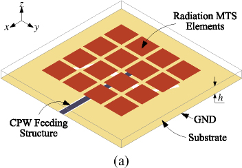
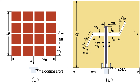
Figure 1: Configurations of the proposed CP MSA. (a) 3D view of the CP MSA. (b) Top view of the radiation MTS elements. (c) Bottom view of the CPW feeding structure. (unit: mm) 4.0, 46.0, 46.0, 10.0, 2.0, 70.0, 70.0, 2.5, 4.0, 28.7, 3.6, 16.0, 2.0, 8.0, 3.5, .
II. PROPOSED CP MSA AND CMA ANALYSIS
A. Geometry of the CP MSA
As depicted in Fig. 1 (a), the configuration of the proposed CP MSA is printed on the top surface of the square substrate (F4BM300) with a relative dielectric constant of 3.0 and a loss tangent of 0.002. The CPW feeding structure combines a horizontal aperture and two counter-clockwise rotated slots, which are coated on the bottom of the slab with a profile height . MTS is comprised of a 44 uniformly spaced square MTS elements array and located on the top side of the substrate as depicted in Fig. 1 (b). All the square MTS elements are kept with the same side length and the spacing of the MTS elements in both - and -axis directions is . It can be seen from Fig. 1 (c), the horizontal aperture with a length of and a width of , which will combine two counter-clockwise rotated slots with a length of and a width of as the CP radiation source for the proposed MTS elements.
B. Design process of the CP MSA
In the domain of CP radiation antenna design, the focal point resides in crafting an electric field or magnetic field with the same amplitude but a phase difference of 90 within the interested frequency band. Herein, the CMA is employed to select the wanted modes of the MSA for 5G Wi-Fi band utilization in this paper. It’s worth mentioning that the CPW feeding structure and the coupling slots are removed from the ground plane of the 44 MTS elements during the process of CMA. Furthermore, the size of the ground plane is set to infinity and the PEC boundary conditions are imposed on the MTS elements and ground plane respectively.
The characteristic modes of the proposed MSA are analyzed by CST microwave studio ranging from 4 GHz to 7 GHz. The first five modes and their related modal significance (MS), modal surface current distributions, and the 3D radiation patterns are presented in Fig. 2. Regarding the MS, a value of 1 indicates an effective resonance, while a value of 0 signifies the absence of resonance excitation. It can be observed from the MS for Mode 1 and Mode 2 in Fig. 2, that a complete coincidence occurs in the whole frequency band. Meanwhile, the modal currents of for Mode 1 are orthogonal to for Mode 2, which are consistent with our common sense due to the excellent symmetry on physical scale of the proposed MTS elements. The even current distribution in the diagonal direction on each MTS surface for and will cause a high directivity with 11.6 dBi at 6 GHz.
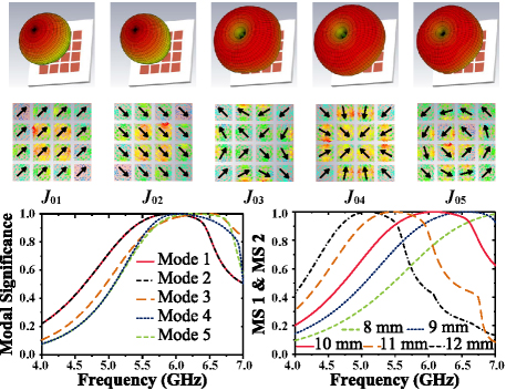
Figure 2: Modal significance, modal current, and radiation patterns of the first five modes for the 4 4 square MTS antennas.
With respect to the last three modal currents , , and , the currents on their corresponding MTS elements are presented as the centrally symmetric but out-of-phase distribution. As a consequence, the radiation nulls will be found in the boresight direction for the associated modal currents , , and . For this reason, modal currents and are the targeted modes for boresight radiation in the frequency band of 5G Wi-Fi. Figure 2 also illustrates the changing tendency of MS for the first two modes (modes 1 and 2) from 4.0 GHz to 7.0 GHz. It’s found that the resonance frequency of the MSA, when MS1 and MS2 are both equal to 1, decreases with the increase in the size of the MTS elements. When equals to 10.0 mm, the MS1 and MS2 are both larger than 0.707, ranging from 5 GHz to 6.6 GHz, therefore an optimal -10 dB IBW of the MSA for 5G Wi-Fi can be obtained [12, 15]. Although these two modes can be excited simultaneously at 45 and 45 , respectively, the resulting radiation pattern remains linearly polarized due to the lack of a phase difference betweenthe modes.
To achieve a broadband CP radiation antenna during the interested frequency band, the CP radiation feed structure with a phase difference can be adopted to excite the two mutually orthogonal modes (Mode 1 and Mode 2). As shown in Fig. 1 (c), the horizontal aperture combines two counter-clockwise rotated slots and is considered as a CP radiation source for the proposed MTS elements. For the aims of further reducing the profile height and the number of dielectric layers of the MSA, the CPW feeding structure is employed to excite the CP radiation slots for the proposed square MTS elements.
As shown in Fig. 3, the folded dipole antenna is used to explain the generating mechanism of phase difference of the CP radiation source. The simulated reflection coefficient of it has two resonance modes. The surface current of Mode 1 of at 2.7 GHz characterizes the traditional dipole antenna and propagates along with the dipole antenna from one end to another, therefore a linear polarization wave with a high AR value of 39 occurs at 2.7 GHz. However, when the antenna works at Mode 2 of (higher-order mode) at 6.5 GHz, the direction of the current distribution of two rotated arms is opposite to the direction of Mode 1 of . Due to this, the phase difference can be obtained, therefore the corresponding AR value at 6.5 GHz declines obviouslyto 10 dB.
Figure 3: Simulated reflection coefficient and AR for the folded dipole antenna.
According to the mirror equivalent principle in the electromagnetic field, a coupling slot antenna with a phase difference can be simultaneously obtained from the folded dipole antenna as given in Fig. 4 (a) of the coupling slot antenna. Instead of an ideal lumped port for the slot antenna, the CPW transmission line with a matching stub is employed to excite the slot. So the electromagnetic waves from the feeding port will propagate along with the 50-ohm feeding line and then reach the proposed CP radiation slots with a phase difference to simultaneously excite the selected square MTS elements. As shown in Fig. 4 (b), the simulated CP radiation slot with a -6 dB IBW covers from 5.0 GHz to 5.8 GHz. Furthermore, the radiation pattern for the CP source is radiation towards direction and the AR declines simultaneously, which means this CP radiation slot could be utilized to excite the proposed square MTS elements in the Wi-Fi band.
To further validate it, Fig. 5 also illustrates the phase difference between the and in the boresight direction and ratio of of the CP radiation source and CP MSA. Obviously, the phase difference of the CP radiation slot is located around from to , which further verifies that a phase difference can be obtained by the proposed CP radiation slot. In addition, when the selected square MTS elements are loaded upon the radiation slot, the phase difference of the CP MSA is located around from 78° to 93°. Moreover, the ratio of also nears 1 ranging from 4.8 GHz to 5.8 GHz, which means a wideband CP antenna is obtained.
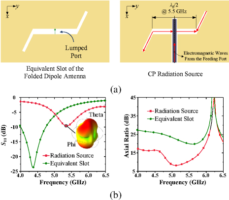
Figure 4: (a) The equivalent slot of the folded dipole antenna and the proposed CP radiation source and (b) Simulated reflection coefficient and AR of themselves.
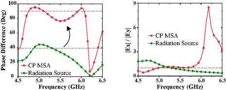
Figure 5: The phase difference and ratio of of the CP radiation source and CP MSA.
C. Parameters analysis
The coupling radiation slots of the proposed CP MSA serve as a crucial structure for achieving CP radiation. Hence, analyzing its dimensions is essential for determining both the reflection coefficient and AR. Figure 6 (a) presents the effects of the counter-clockwise rotated slot length on antenna performance. To better analyze the impacts of the key parameters on the performance of the proposed CP MSA, the single factor variable method is adopted. It can be observed that the -10 dB IBW of the CP MSA increases synchronously with the increase of ranging from 14 mm to 18 mm. However, the 3 dB AR bandwidth exhibits a trend of initially increasing and then decreasing, with the optimal 3 dB AR bandwidth achieved at a value of 16 mm for .
After that, the rotated angle between the counter-clockwise rotated slot and -axis is studied in Fig. 6 (b). It is found that the influence of rotation angle on the IBW is relatively minor compared to its depth, with the value of increasing the AR bandwidth also increases and tends to be stable from 16 to 26. Considering the depth of -10 dB IBW, the desired rotated angle with a value of 26 for is selected in this CP MSA.
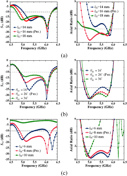
Figure 6: The effects of the CP radiation structure parameters (a) , (b) , and (c) on the reflection coefficient and AR of the CP MSA.
The impacts of the open matching stub length of the 50-ohm CPW feeding line are also analyzed in Fig. 6 (c). The length of significantly affects the reflection coefficient and AR. The tendency for 3 dB AR bandwidth of the CP MSA shows decreases with the increase of . Considering the IBW will mismatch when equals 6 mm and 10 mm, respectively. The selected value for is 8 mm. The dimension parameters for the CP radiation slots are given in the caption ofFig. 1.
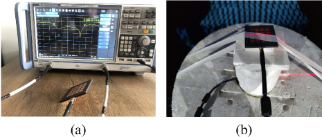
Figure 7: Photographs of the proposed CP MSA under testing: (a) reflection coefficient and (b) far-field radiation performance.
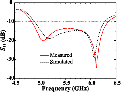
Figure 8: The simulated and measured reflection coefficient of the proposed CP MSA.
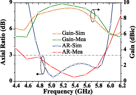
Figure 9: The simulated and measured AR and gain at boresight direction of the proposed CP MSA.
III. EXPERIMENTAL VERIFICATION
In order to validate the proposed CP MSA, a prototype of it is fabricated and tested. As shown in Fig. 7 (a) the Rohde & Schwarz ZND vector network analyzer is employed to test the reflection coefficient . As depicted in Fig. 8, the measured -10 dB IBW spans from 4.83 GHz to 6.35 GHz, with a fractional bandwidth of 27.2%, demonstrating excellent agreement with the simulated results. The far-field radiation performance including the radiation pattern, AR bandwidth, and the boresight gain of the proposed CP MSA is tested in the microwave anechoic chamber as presented in Fig. 7 (b). It can be observed from Fig. 9, that the measured 3 dB AR bandwidth ranges from 4.53 GHz to 5.91 GHz, and the overlapped fractional bandwidth achieves 20.6% (from 4.83 GHz to 5.91 GHz) which is better than the simulated one. Furthermore, the measured peak boresight gain at 5.2 GHz is 9.88 dBic, and the average boresight gain during the whole overlapped bandwidth obtains 8.94 dBic which shows excellent far-field radiation performance.
With respect to Fig. 10, which shows the normalized far-field radiation pattern in the plane and plane at 5 GHz and 5.8 GHz respectively. The measured right-handed (RH) CP (co-polarized) radiation patterns of the proposed CP MSA at both frequencies present good consistency with the simulated ones. The measured left-handed (LH) CP (cross-polarized) radiation patterns show a slight difference from the simulated ones, which may be attributed to the effects of the test environment. However, the levels of the LHCP at the boresight direction are all less than -20 dB, showing the perfect working performance of the proposed CP MSA again.
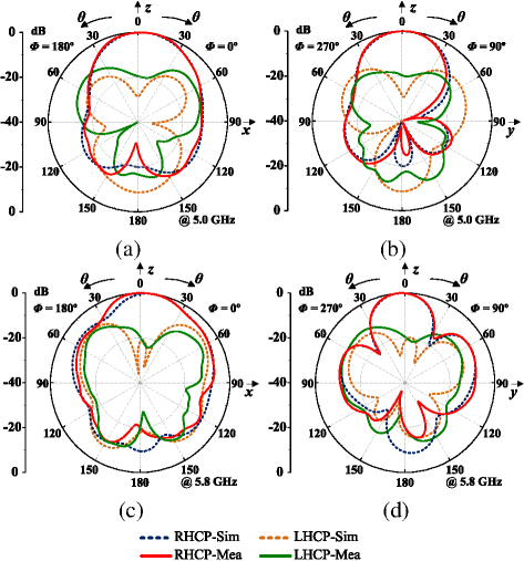
Figure 10: The simulated and measured normalized radiation patterns for (a) plane at 5.0 GHz, (b) plane at 5.0 GHz, (c) plane at 5.8 GHz, and (d) plane at 5.8 GHz.
A performance comparison with the related works published in recent years is listed in Table 1. The primary contribution of the antenna in [17] is a low antenna aperture size, but the profile height reaches 0.19 and the peak gain of the antenna is only 5.76 dBic. The merits of the antenna in [18, 20, 22] attribute to the low-profile height, however, the double-layer plate structure makes its manufacturing process more complicated. In [21], a larger AR bandwidth is obtained, but the double-layer structure and the peak gain of 7 dBic of the antenna is still not very good. In [23] and [25], the superiority of it is the single-layer and low-profile design, but the overlapped 3 dB AR bandwidth and the peak gain of the antenna are not very satisfactory. With respect to the proposed CP MSA in this paper, the peak boresight gain achieves 9.88 dBic, and the overlapped 3 dB AR bandwidth is 20.1%. The 3 dB gain bandwidth covers the whole overlapped 3 dB AR bandwidth while maintaining the low-profile and single-layer design.
Table 1: Performance comparison with related works in recent years
| Ref. | Antenna Aperture () | Thickness () | Over-Lapped ARBandwidth | Peak Gain (dBic) | Layer |
| [17] | 0.19 | 15.9% | 5.76 | 2 | |
| [18] | 0.09 | 20.0% | 8 | 2 | |
| [20] | 0.07 | 16.5% | 5.8 | 2 | |
| [21] | 0.04 | 31.3% | 7.01 | 2 | |
| [22] | 0.04 | 14.5% | 7 | 2 | |
| [23] | 0.04 | 12.8% | 6.9 | 1 | |
| [25] | 0.06 | 16.6% | 8 | 1 | |
| This work | 0.07 | 20.1% | 9.88 | 1 |
where represents the free-space wavelength at the center frequency in the 3 dB overlapped AR operating bandwidth.
IV. CONCLUSION
In this paper, a low-profile, broadband, single-layer, and high-gain CP MSA is proposed. With the assistance of CMA, the useful modes and are selected for 5G Wi-Fi band utilization. To achieve the RHCP radiation of the MSA, the horizontal aperture combines two slots rotated in a counter-clockwise direction to excite the MS structure. The prototype of the CP MSA is fabricated and measured. The tested results correlate well with the simulated ones. The peak boresight gain of 9.88 dBic is obtained at 5.2 GHz, and the -10 dB IBW achieves from 4.83 GHz to 6.35 GHz, moreover, the 3 dB gain bandwidth covers its whole 3 dB overlapped AR bandwidth (20.1%, from 4.83 GHz to 5.91 GHz) and the average gain at the boresight direction can reach 8.94 dBic. The profile of the prototype of this CP MSA is only 0.07 , and the single-layer structure design makes the proposed CP MSA more promising in practical application.
ACKNOWLEDGMENT
The authors would like to express their gratitude for the generous support in part by the Natural Science Foundation of Fujian Province under Grant 2023J01967, in part by the Fundamental Research Funds in Heilongjiang Provincial Universities under Grant 145109145, and in part by the Heilongjiang Higher Education Teaching Reform Research Project under Grant SJGY20220403.
REFERENCES
[1] W. Yang, J. Zhou, Z. Yu, and L. Li, “Single-fed low profile broadband circularly polarized stacked patch antenna,” IEEE Transactions on Antennas and Propagation, vol. 62, no. 10, pp. 5406–5410, Oct. 2014.
[2] J. Wang, X. Liu, P. Zhang, Z. Xu, A. Li, Z. Chen, and J. Fan, “Wideband center-fed stacked patch circularly polarized antenna used in phased array,” Applied Computational Electromagnetics Society (ACES) Journal, vol. 38, no. 10, pp. 774–782, Oct. 2023.
[3] T. Mondal, S. Samanta, R. Ghatak, and S. R. B. Chaudhuri, “A novel hexagonal wideband circularly polarized stacked patch microstrip antenna,” Microwave and Optical Technology Letters, vol. 57, no. 11, pp. 2548–2554, 2015.
[4] K. L. Chung and A. S. Mohan, “A circularly polarized stacked electromagnetically coupled patch antenna,” IEEE Transactions on Antennas and Propagation, vol. 52, no. 5, pp. 1365–1369, May 2004.
[5] K. L. Chung, W. Li, Y. Li, R. Liu, and P. Zhang, “Chinese character-shaped artistic patch antenna,” Alexandria Engineering Journal, vol. 18, no. 8, pp. 1542–1546, 2019.
[6] S. Mohammadi-Asl, J. Nourinia, C. Ghobadi, and M. Majidzadeh, “Wideband compact circularly polarized sequentially rotated array antenna with sequential-phase feed network,” IEEE Antennas and Wireless Propagation Letters, vol. 16, pp. 3176-3179, 2017.
[7] L. Berretti, S. Maddio, G. Pelosi, M. Righini, and S. Selleri, “A six-elements circularly polarized sequential array for dedicated short range communications in C-band,” Applied Computational Electromagnetics Society (ACES) Journal, vol. 33, no. 10, pp. 1117-1122, Oct. 2018.
[8] K.-F. Tong and T.-P. Wong, “Circularly polarized U-slot antenna,” IEEE Transactions on Antennas and Propagation, vol. 55, no. 8, pp. 2382–2385, Aug. 2007.
[9] J. Zeng, X. Liang, L. He, F. Guan, F. H. Lin, and J. Zi, “Single-fed triple-mode wideband circularly polarized microstrip antennas using characteristic mode analysis,” IEEE Transactions on Antennas and Propagation, vol. 70, no. 2, pp. 846–855, Feb. 2022.
[10] M. S. Ibrahim, “Design of low-cost, circularly polarized, and wideband U-slot microstrip patch antenna with parasitic elements for WiGig and WPAN applications,” IEEE Antennas and Wireless Propagation Letters, vol. 65, no. 9, pp. 1453–1456, Sep. 2019.
[11] L. Wang, Z. Zhu, and Y. En, “Performance enhancement of broadband circularly polarized slot–microstrip antenna using parasitic elements,” IEEE Antennas and Wireless Propagation Letters, vol. 20, no. 12, pp. 2255–2259, Dec. 2021.
[12] F. H. Lin and Z. N. Chen, “Resonant metasurface antennas with resonant apertures: Characteristic mode analysis and dual-polarized broadband low-profile design,” IEEE Transactions on Antennas and Propagation, vol. 69, no. 6, pp. 3512–3516, June 2021.
[13] D. Chen, W. Yang, Q. Xue, and W. Che, “Miniaturized wideband planar antenna using inter-embedded metasurface structure,” IEEE Transactions on Antennas and Propagation, vol. 69, no. 5, pp. 3021–3026, May 2021.
[14] Z.-J Han, W. Song, and X. Q. Sheng, “Broadband circularly polarized antenna by using polarization conversion metasurface,” Applied Computational Electromagnetics Society (ACES) Journal, vol. 69, no. 5, pp. 656–661, June 2020.
[15] Y. Chen and C.-F. Wang, Characteristic Modes: Theory and Applications in Antenna Engineering. Hoboken, NJ: John Wiley & Sons, 2015.
[16] J. F. Gao and F. H. Lin, “Modeling and analysis of wideband multilayer metasurface antenna array using characteristic-mode analysis,” IEEE Transactions on Antennas and Propagation, vol. 71, no. 3, pp. 2832–2836, Mar. 2023.
[17] M. Ameen and R. K. Chaudhary, “Metamaterial-based wideband circularly polarised antenna with rotated V-shaped metasurface for small satellite applications,” Electronics Letters, vol. 55, no. 7, pp. 365–366, 2019.
[18] Y. Huang, L. Yang, J. Li, Y. Wang, and G. Wen, “Polarization conversion of metasurface for the application of wide band low-profile circular polarization slot antenna,” Applied Physics Letters, vol. 109, p. 051401, 2016.
[19] W. Li, W. Xue, Y. Li, X. Xiong, K. L. Chung, and Z. Huang, “Wideband single-fed circularly polarized stacked patch antenna with L-shaped stub,” Applied Computational Electromagnetics Society (ACES) Journal, vol. 37, no. 12, pp. 1240–1248, Dec. 2022.
[20] Z. Wu, L. Li, Y. Li, and X. Chen, “Metasurface superstrate antenna with wideband circular polarization for satellite communication application,” IEEE Antennas and Wireless Propagation Letters, vol. 15, pp. 374–377, 2016.
[21] S. X. Ta and I. Park, “Low-profile broadband circularly polarized patch antenna using metasurface,” IEEE Transactions on Antennas and Propagation, vol. 63, no. 12, pp. 5929–5934, Dec. 2015.
[22] S. Liu, D. Yang, and J. Pan, “A low-profile circularly polarized metasurface antenna with wide axial-ratio beamwidth,” IEEE Antennas and Wireless Propagation Letters, vol. 18, no. 7, pp. 1438–1442, July 2019.
[23] Z. Liang, J. Ouyang, and F. Yang, “Low‐profile wideband circularly polarised single‐layer metasurface antenna,” Electronics Letters, vol. 54, no. 24, pp. 1362–1364, 2018.
[24] Y. Juan, W. Yang, and W. Che, “Miniaturized low-profile circularly polarized metasurface antenna using capacitive loading,” IEEE Transactions on Antennas and Propagation, vol. 67, no. 5, pp. 3527–3532, May 2019.
[25] A. El Yousfi, A. Lamkaddem, K. A. Abdalmalak, and D. Segovia-Vargas, “A broadband circularly polarized single-layer metasurface antenna using characteristic-mode analysis,” IEEE Transactions on Antennas and Propagation, vol. 71, no. 4, pp. 3114–3122, Apr. 2023.
BIOGRAPHIES

Yibiao Fan received his B.S. degree from Minnan Normal University, Zhangzhou, China, in 2006, and M.S. degree from Huaqiao University, Quanzhou, China, in 2015. Presently, he serves as an associate professor and M.S. Candidate Advisor for College of Physics and Mechatronic Engineering of Longyan University, Longyan, China. His current research interests include metamaterial and microwave antennas.

Zhan Jin received the B.S. degree in Electrical and Information Engineering from Heilongjiang University, Harbin, China, in 2005, and M.S. degree and Ph.D. degree in Information and Communication Engineering from Harbin Engineering University, Harbin, China, in 2009 and 2020, respectively. She joined Qiqihar University, Qiqihar, China, in 2009, where she is currently an associate professor and M.S. Candidate Advisor with the College of Communication and Electronic Engineering. Her current research interests include signal processing, sparse adaptive filtering, and microwave antennas.

Xiaowei Cai was born in Zhangzhou, Fujian, China, in 1986. He received the B.S. degree in electronic information engineering and the M.S. degree in control engineering from Nanchang University, Jiangxi, China, in 2007 and 2013, respectively. Presently, he serves as an associate professor and M.S. Candidate Advisor for College of Physics and Mechatronic Engineering of Longyan University, Longyan, China. His current research interests include intelligent sensing and circularly antennas.

Zhihe Fu was born in Longyan, China, in 1970. He received the B.S. degree in materials physics from Fujian Normal University, Fuzhou, China, in 1992, and the M.S. degree in electronics and communications from Fuzhou University, Fuzhou, in 2011. He joined Longyan University, Longyan, China, in 1992, where he is currently a professor and M.S. Candidate Advisor for College of Physics and Mechatronic Engineering of Longyan University, Longyan, China. His current research interests include electric power systems measurement and control technologies.

Qi Lin is currently pursuing the B.S. degree in communication engineering with Qiqihar University, Qiqihar, China. Her research interests include signal processing, sparse adaptive filtering, and microwave antenna design.
ACES JOURNAL, Vol. 40, No. 5, 401–408
doi: 10.13052/2025.ACES.J.400503
© 2025 River Publishers