Accurate Measurement of Wake Height Caused by Target Motion using Millimeter-wave Radar
Yan Jia, Yifan Gong, Limin Zhai, Yongqing Liu, and Xiangkun Zhang
1Key Lab of National Microwave Remote Sensing National Space Science Center
Chinese Academy of Sciences, Beijing 100190, China
jiayan18@mails.ucas.ac.cn, zhangxiangkun@mirslab.cn
2School of Electronic, Electrical and Communication Engineering
University of Chinese Academy of Sciences, Beijing 100490, China
Submitted On: July 24, 2024; Accepted On: January 20, 2025
ABSTRACT
This study explores the feasibility of using millimeter-wave radar to observe ship wake wave heights on the water surface and proposes an accurate measurement method based on Frequency-Modulated Continuous Wave (FMCW) radar to detect water surface elevation changes caused by ship motion. By acquiring electromagnetic echo signals from the water surface using millimeter-wave radar and applying interference principles, high-precision measurements of water surface elevation changes are achieved. We conducted numerical simulations of the ship wake using computational fluid dynamics (CFD) based on an actual ship model and performed wake wave height measurements using high-resolution radar parameters. By comparing the radar measurement data with those from a capacitive wave height meter, the effectiveness of the AWR2243 FMCW millimeter-wave radar in measuring wake wave heights induced by ship motion was validated. Time-frequency analysis of the wake wave height using wavelet transform indicated that the primary frequency of the wake diffusion wave generated by the experimental ship model’s movement was around 2 Hz. The experimental results demonstrate that FMCW millimeter-wave radar can achieve high-precision water surface wave height measurements. The radar’s application in oceanic target wake observation has great potential, providing new technical means for ship monitoring, marine scientific research, and ocean environmental monitoring.
Index Terms: FMCW Millimeter-wave radar, high range resolution and high precision, ship wakes, wave height.
I. INTRODUCTION
Ocean remote sensing primarily focuses on two major observational areas: ecological, encompassing sea surface spectral characteristics, radiative properties, pigments, and pollutants; and dynamic parameters, which include sea surface height, temperature, and salinity[1, 2]. Ship wakes represent a small-scale ocean dynamic phenomenon impacting the sea surface state. In specific locations, ship wakes can significantly affect coastlines and waterways [3]. Given the increased ship size and speed, along with heightened ship traffic intensity, monitoring and analyzing ship wakes becomes essential for effective ocean monitoring [3, 4]. Accurately measuring changes in sea surface wave height due to ship wakes provides a reliable detection method, crucial for various coastal and oceanographic operations [5].
Now, the primary methods for measuring wave height on the water surface and its wakes include contact and non-contact methods. The most common contact measurement devices are wave pressure sensors and sea surface buoys. Contact sensors can only perform single-point measurements of water surface elevation, and their calibration relies on laboratory simulations. In contrast, buoy technology is more mature and can measure sea surface elevation by analyzing the displacement of the buoy over a period of time, but its accuracy is relatively low [6, 7]. Non-contact measurement methods mainly include photographic optical measurements, laser measurements [8], and ground-based or spaceborne microwave radar. Photographic optical measurements can provide extensive sea surface information, but the computational process is complex and constrained by lighting conditions and camera resolution [9]. Laser measurements can accurately determine the vertical height from the instrument to the sea surface but are highly sensitive to water quality. Millimeter-wave radar is particularly recognized for its high-resolution capability. Its small antenna size, narrow beam width, and high precision allow for all-weather communication capabilities. Frequency-Modulated Continuous Wave (FMCW) radar features low transmission power, high reception sensitivity, high range resolution, simple structure, and ease of integration, making it widely used in high-precision measurement fields.
Currently, various types of radar are widely used for sensing and processing weak signals, including synthetic aperture radar, radar altimeters, microwave scatterometers, and microwave radiometers. Most of these devices can estimate wave height based on the intensity of the received electromagnetic waves [10, 11]. Some studies analyze sea surface waves, retrieving wave heights using ocean radar image sequences [11], while other studies can obtain effective wave heights based on the variation of the Doppler speed measured by X-band radars [12, 13, 14]. Additionally, K-band continuous wave radars are utilized to estimate short-range wave heights [15].
In this study, we employed a 77 GHz millimeter-wave radar to observe the water surface and utilized FMCW interferometry to measure water surface elevation. The second section of this paper introduces the basic theory of millimeter-wave radar interferometry. The third section details the verification of the measurement accuracy of the 77 GHz FMCW millimeter-wave radar system. The fourth section presents the simulation of the ship model wake using computational fluid dynamics (CFD). The fifth section details the surface wake wave height measurement experiment and discusses and analyzes the results. The sixth section concludes the paper.
II. MEASUREMENT PRINCIPLE OF THE 77GHz MM-WAVE RADAR
The TI AWR2243 is a linear FMCW radar operating within the 77-81 GHz frequency range [16, 17]. In this radar system, the transmit (TX) signal comprises a series of signals whose frequency changes linearly over time [18, 19]. These linearly frequency-modulated signals are represented in the AWR2243 as ”frame” data. Figure 1 illustrates a frame of data from the AWR2243, along with models of a single chirp signal for both transmission and reception.
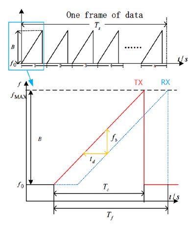
Figure 1: One frame of transmission signals and a set of transmitting and receiving signal models in the AWR2243 radar.
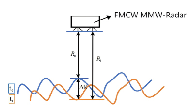
Figure 2: The signal transmission model of the FMCW millimeter-wave radar.
The signal transmission model for wave height measurement of the water surface using the AWR2243 FMCW millimeter-wave radar is shown in Fig. 2. At different time instants, the radar transmits frequency-modulated continuous signals to the water surface, and the variation in water surface elevation at different moments can be obtained from the received echo signals. Assuming the radar transmits a single sawtooth linear frequency modulation (LFM) signal, the mathematical model for the transmission signal of the FMCW MMW radar at a given time is described as follows:
| (1) |
where represents the amplitude of the transmitted signal, denotes the random initial phase, indicates the starting frequency of the signal, and signifies the frequency modulation slope. The received signal, after the radar transmits its signal and it reflects off the water surface, can be expressed as:
| (2) | |||
| (3) |
In equation(2) , represents the amplitude of the received signal, and is the echo delay related to the distance between the radar and the water surface along the radial direction.In the signal transmission path shown in Fig. 2, represents the instantaneous distance between the varying water surface and the radar antenna. By mixing and demodulating the received signal with the transmitted signal, the intermediate frequency (IF) signal can be obtained as:
| (4) |
When the distance changes slightly by , from the interferometry principle, the relationship between echo phase change and distance change is given by [20]:
| (5) |
where is the radar wavelength.
III. ACCURACY VERIFICATION OF THE FMCW MM-WAVE RADAR
The measurement method described above has been extensively studied for targets such as bridges; however, research on using FMCW millimeter-wave radar for water surface measurement is limited. Therefore, prior to deploying Texas Instruments’ AWR2243 millimeter-wave radar for monitoring water surface wave height variations, it is crucial to verify its micro-deformation measurement accuracy. The AWR2243 radar features three transmitting antennas and four receiving antennas. For the experimental verification, we used only one transmitting antenna and one receiving antenna. During the experiment, we also utilized the DCA1000EVM data acquisition card for data collection and TI’s MMwave Studio software for experimental parameter configuration. The radar parameters allow for flexible configuration, with the specific parameters used in the indoor experiments shown in Table 1.
Table 1: Indoor experimental parameters of the AWR2243 MMW radar
| Parameter | Value |
| Start Frequency (GHz) | 77 GHz |
| Frequency Slope (MHz/) | 30 MHz/ |
| Bandwidth | 767.54 MHz |
| Sample Rate | 10 MHz |
| PRF | 1600 Hz |
| Distance Resolution | 0.19 m |
The indoor accuracy verification of the AWR2243 is depicted in Fig. 3. Figure 3 (a) shows a micro-deformation calibration apparatus composed of a micrometer and a corner reflector.These components are rigidly connected, with the micrometer driving the corner reflector to move along a non-metallic surface, achieving a displacement accuracy of 0.01 mm. Figure 3 (b) shows the indoor experimental scene. In the experiment, the corner reflector was positioned approximately 3m in front of the radar, with both the radar and the corner reflector at the same horizontal level. During the experiment, the micrometer scale was precisely adjusted to move the corner reflector 0.5 mm toward the radar each time, repeating this process nine times. After each movement of the corner reflector, the radar transmitted a chirp signal and collected and processed the corresponding echo data. In the end, 10 sets of echo data were recorded for the corner reflector at different positions.
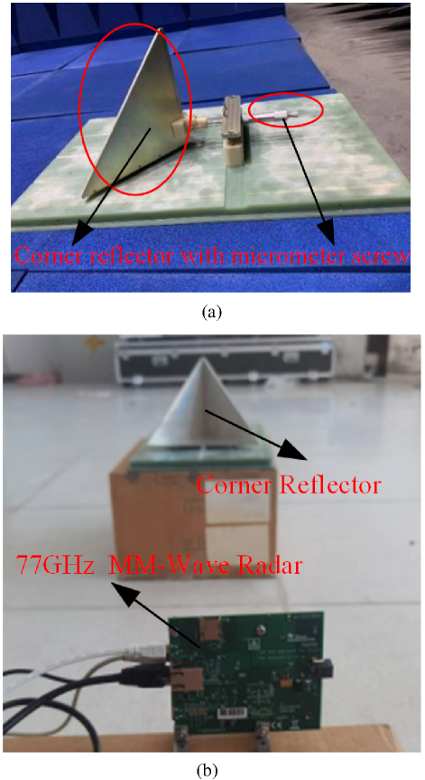
Figure 3: (a) The micrometer screw gauge coupled with a corner reflector and (b) indoor experiment scene.
Figure 4 (a) shows the range compressed images of the corner reflector’s echo signals at 10 different positions. The horizontal axis represents the number of frequency-modulated linear signals in the 10 measurements, while the vertical axis corresponds to the actual distance for each range gate. It can be observed that the corner reflector is positioned between 3m and 3.5m, with the manually measured distance between the corner reflector and the radar being 3.24 meters. Figure 4 (b) presents the displacement of the corner reflector across the 10 sets of data. From the figure, it can be seen that the radar recorded the initial position of the corner reflector as well as the displacement after each movement, with each displacement being 0.5mm, resulting in a total movement of 4.5cm.
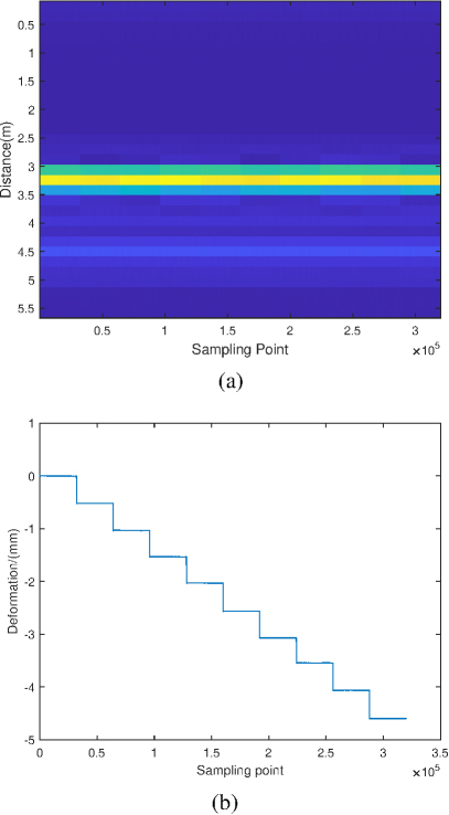
Figure 4: (a) Image of point target echo range compression and (b) deformation results of 10 sets of corner reflector echo data.
To verify the accuracy of the results, the Root-Mean-Square Error (RMSE) for each set of data in the table is calculated, which can be expressed as:
| (6) | |||
| (7) |
where is the number of radar transmitted signals at each location. The average RMSE from the 10 groups previously mentioned can be utilized to determine the measurement accuracy of the radar system. The calculation indicates that the measurement accuracy of the AWR2243 can achieve .
IV. CFD SIMULATION OF THE WAKE GENERATED BY THE EXPERIMENTAL SHIP MODEL
Before conducting the ship wake measurement experiment in the water tank, we used CFD to numerically simulate the changes in wave height caused by the ship’s wake on the water surface. The actual ship dimensions and its scaled model are shown in Fig. 5, with the ship model measuring 43 cm × 13 cm × 10 cm. The CFD simulation of the ship’s wake was based on Reynolds-Averaged Navier-Stokes (RANS) equations and implemented using the STAR-CCM+ software platform. In the simulation, the wake scenario was modeled within a computational domain of 10 meters in length and 6 meters in width, with a ship’s draft of 3 cm and a speed of 1.5 m/s. The grid distribution and simulation results are shown in Fig. 6. To minimize simulation errors, the grid density near the water surface was refined in the CFD computational domain.
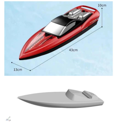
Figure 5: Experimental ship model size and simulation ship model.
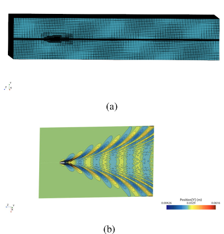
Figure 6: (a) CFD computational domain mesh scenario and (b) simulation results of the CFD simulation.
Based on the CFD simulation results, the wake generated by the ship model on the water surface is identified as a Kelvin wake, exhibiting distinct characteristics, including a wake angle of approximately 39°, composed of both diffusion waves and transverse waves. After interpolating the wake height data obtained from the CFD simulation, as shown in Fig. 7, we obtained a 2D wave height distribution image. The figure indicates that the wake height distribution ranges within ±25 mm, with the maximum wave height occurring along the centerline. Theoretically, when the ship moves at a constant speed , the wavelength of the generated wake waves can be calculated using the followingformula:
| (8) |
where is the ship’s speed, represents the angle between the wave propagation direction and the ship’s motion, and is the gravitational acceleration.
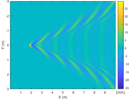
Figure 7: Wake height distribution after interpolation reconstruction.
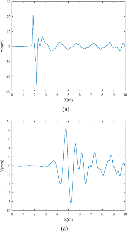
Figure 8: (a) Wave height at the wake centerline and (b) at a distance of 1 meter from the wake centerline.
Figure 8 presents the one-dimensional wave height curves at the wake centerline and at a distance of 1m from the centerline. In the one-dimensional wave height curve at the wake centerline, the waveform consists of significant undulations formed by Bernoulli hills and transverse wave components. When calculating the theoretical transverse wave wavelength, the in equation (8). The calculation results indicate that when the ship speed is 1.5 m/s, the theoretical transverse wave wavelength is 1.4426 m. By statistically averaging the peak positions of the transverse waves in Fig. 8 (a), the CFD simulated wavelength is determined to be 1.4533 m.
V. EXPERIMENT AND ANALYSIS OF SHIP WAKE WAVE HEIGHT MEASUREMENTS
After verifying the indoor micro-deformation monitoring accuracy and the simulated wake wave height, we set up a ship wake measurement experiment in a pool. In the outdoor experiment, both the AWR2243 FMCW millimeter-wave radar and the digital capacitive wave height meter were used to simultaneously measure the water surface height variations caused by the ship’s wake. The digital capacitive wave height meter is shown in Fig. 9. Its operating principle is based on the real-time variation in the inter-electrode capacitance of the capacitive sensor line as the water level fluctuates. The signal acquisition chip then converts the capacitance value into a wave height measurement, allowing for accurate water depth measurement. The effective measurement range of the capacitive wave height meter is 50 cm, with a wave height measurement frequency of1000 Hz.
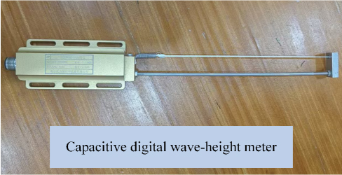
Figure 9: Capacitive digital wave height meter.
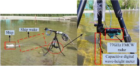
Figure 10: Experimental setup for measuring ship wake wave heights in a water pool.
Figure 10 shows the outdoor experimental setup and equipment arrangement. In the wake wave height measurement experiment, both the capacitive wave height meter and the millimeter-wave radar were positioned at the same location. The radar was installed at a certain height above the water surface, with its antenna vertically illuminating the water, while the capacitive wave height meter was vertically submerged in the water. The measurements from the capacitive wave height meter and the millimeter-wave radar did not interfere with each other. The ship model moved back and forth at a constant speed along a straight line, 1 meter away from the instruments. Both the radar and the digital wave height meter simultaneously measured the variations in the water surface height. Due to the small wake wave height obtained from the simulation, we considered improving the system parameters of the AWR2243 FMCW millimeter-wave radar to better observe the wake wave height. By increasing the bandwidth of the transmitted signal, we enhanced the radar’s range resolution. The specific improved radar parameters are detailed in Table 2. With these improved parameters, the radar’s range resolution was increased to 0.05 meters.
Table 2: Parameter configuration of mm-wave radar for measuring ship wake wave height
| Parameter | Value |
| Start Frequency (GHz) | 77 GHz |
| Frequency Slope (MHz/) | 117 MHz/ |
| Bandwidth | 2.997 GHz |
| Sample Rate | 10 MHz |
| ADC Samples | 256 |
| PRF | 1000 Hz |
| Distance Resolution | 0.05 m |
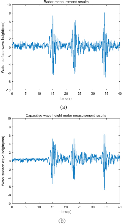
Figure 11: (a) AWR2243 FMCW MMW radar measurement results and (b) capacitive digital wave height meter measurement results.
Figure 11 shows the wave height measurement results from both the radar and the digital wave height meter. As shown in the figure, during the first 10 seconds, the radar recorded the natural fluctuations of the water surface wave height. Around the 15s, 23s, and 34s, when the ship passed the radar, the wake diffusion waves caused by the ship’s wake were accurately captured by the radar. The maximum wake wave height measured by the radar was approximately 7-8 mm. By comparing the wave height data collected by the digital wave height meter in Fig. 11 (a), it is observed that the maximum amplitude of the wake wave height recorded by the wave height meter was smaller than the maximum amplitude recorded by the radar. This discrepancy may be due to the slight mismatch in the measurement positions of the wave height meter and the radar, causing attenuation of the wake diffusion waves as they propagated, resulting in smaller wave heights recorded by the wave height meter. Additionally, we compared the radar measurement results with the maximum wave height from the simulation results shown in Fig. 8 (b). The comparison indicates that the simulation results align with the maximum wave height measured by the radar, further validating the accuracy of the radar measurements.
Using traditional Fourier transform, we analyzed the frequency spectrum of the ship wake diffusion waves in the wave height data. Figure 12 presents the frequency spectrum distribution of two sets of wave height data. The frequency spectrum distributions measured by both the millimeter-wave radar and the wave height meter show a strong similarity, indicating that both measurement methods are consistent in capturing the frequency characteristics of the wake waves. From the figure, it is clearly seen that the frequency components of the ship wake diffusion waves are primarily concentrated between 0 and 5 Hz. This suggests that the fluctuations caused by the ship’s wake have a low-frequency characteristic, predominantly concentrated in the lower frequency range, which is consistent with the physical characteristics of the wake waves and the propagation behavior of the diffusion waves.
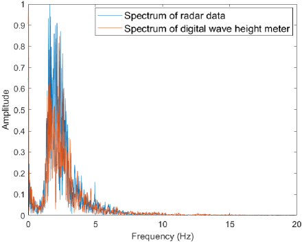
Figure 12: Measurement results from radar and digital wave height meter.
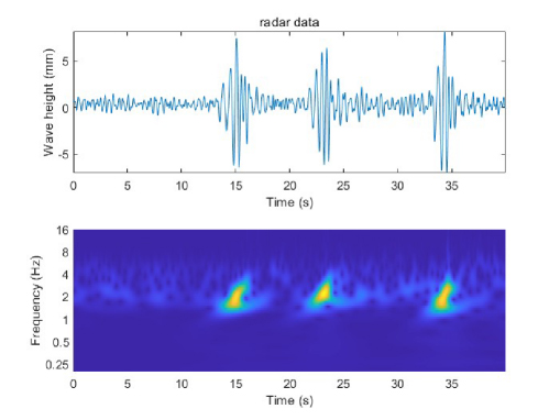
Figure 13: Wavelet time-frequency analysis of radar- measured wake wave height.
Beyond traditional FFT, wake wave height data can also be analyzed using time-frequency analysis techniques. Many time-frequency analysis methods exist, with the three most commonly used being the short-time fast Fourier transform, complex wavelet convolution, and filter-Hilbert [21, 22]. Wavelet time-frequency analysis decomposes the signal into a series of wavelet basis functions, calculating changes in both the time and frequency domains to produce a time-frequency diagram. This analysis technique provides a clearer representation of the time-frequency characteristics of ship wake waves and offers excellent time-frequency resolution and localization properties. Continuous wavelet transform (CWT) is a method to realize wavelet time-frequency analysis that provides a continuous and scalable view of the signal. It is defined by the integral:
| (9) |
where is the the wave height of the wake. is the wavelet function, scaled by and shifted by is the translation parameter (shifts the wavelet in time), while is the scale parameter. The Morlet wavelet, also known as the Gabor wavelet, is a popular wavelet used in CWT for time-frequency analysis of signals [23].
As depicted in Fig. 13, CWT is utilized to perform a time-frequency analysis of the ship wake diffusion wave’s wave height. The radar captured three distinct changes in water surface wave height due to the ship’s wake diffusion waves, with the primary frequencies of these waves centered around 2 Hz. From the experiments and discussions, it is worth noting that the subtle height changes in the water surface waves induced by the ship’s wake can be effectively monitored. To enhance monitoring accuracy, the antenna array should be oriented perpendicular to the water surface.
VI. CONCLUSION
This paper presents a new method for accurately measuring the water surface wave height changes induced by ship motion using a 77 GHz Frequency-Modulated Continuous Wave (FMCW) millimeter-wave radar. The method employs an interferometric measurement approach for surface observation experiments. The experimental results demonstrate that the 77 GHz millimeter-wave radar can effectively monitor the subtle surface fluctuations caused by the diffusion waves of the ship’s wake. By comparing the radar measurement results with those from a digital wave height meter and simulation data, the accuracy and reliability of the method are further validated. However, despite the promising results obtained in the experiments, the current measurements do not fully account for the influence of parameters such as wind speed on wake surface measurements. Moreover, under high sea conditions, there are still certain limitations in measuring wake wave heights. Therefore, future studies may need to incorporate more complex ocean wave models to further improve measurement accuracy andapplicability.
In summary, while the existing method has achieved preliminary success in measuring water surface wave height changes induced by ship motion, there are still many aspects that warrant further exploration and improvement. With continuous technological advancements, the application of millimeter-wave radar in ocean monitoring holds great potential, offering innovative solutions for future marine monitoring and ship identification.
REFERENCES
[1] V. Klemas, “Remote sensing of coastal and ocean currents: An overview,” Journal of Coastal Research, vol. 28, no. 3, pp. 576-586, 2012.
[2] H. Chung-Ru and A. K. Liu, “Preface: Remote sensing applications in ocean observation,” Remote Sensing, vol. 15, no. 2, p. 415, 2023.
[3] M. Rätsep, K. E. Parnell, and T. Soomere, “Detecting ship wakes for the study of coastal processes,” Journal of Coastal Research, vol. 95, no. sp1, pp. 1258-1262, 2020.
[4] K. Parnell, S. McDonald, and A. Burke, “Shoreline effects of vessel wakes, Marlborough sounds, New Zealand,” Journal of Coastal Research, vol. 50, no. sp1, pp. 502-506, 2024.
[5] R. Carrasco, J. Horstmann, and J. Seemann, “Significant wave height measured by coherent X-band radar,” IEEE Transactions on Geoscience and Remote Sensing, vol. 55, no. 9, pp. 5355-5365, 2017.
[6] L. Cavaleri, “Wave measurement using pressure transducer,” Oceanologica Acta, vol. 3, no. 3, pp. 339-346, 1980.
[7] Q. Liu, T. Lewis, Y. Zhang, and W. Sheng, “Performance assessment of wave measurements of wave buoys,” International Journal of Marine Energy, vol. 12, pp. 63-76, 2015.
[8] J. Wang, G. Hou, Y. Liu, and H. Jiang, “Research on shipboard wave measurement instrument based on laser technology,” Ocean. Technol, vol. 23, pp. 14-17, 2004.
[9] A. Benetazzo, “Measurements of short water waves using stereo matched image sequences,” Coastal Engineering, vol. 53, no. 12, pp. 1013-1032,2006.
[10] S. Martin, An Introduction to Ocean Remote Sensing, Cambridge, Cambridge University Press, 2014.
[11] J. C. N. Borge, K. Reichert, and J. Dittmer, “Use of nautical radar as a wave monitoring instrument,” Coastal Engineering, vol. 37, no. 3-4, pp. 331-342, 1999.
[12] H. Dankert, J. Horstmann, S. Lehner, and W. Rosenthal, “Detection of wave groups in SAR images and radar image sequences,” IEEE Transactions on Geoscience and Remote Sensing, vol. 41, no. 6, pp. 1437-1446, 2003.
[13] R. Carrasco, M. Streßer, and J. Horstmann, “A simple method for retrieving significant wave height from Dopplerized X-band radar,” Ocean Science, vol. 13, no. 1, pp. 95-103, 2017.
[14] J. T. Johnson, R. J. Burkholder, J. V. Toporkov, D. R. Lyzenga, and W. J. Plant, “A numerical study of the retrieval of sea surface height profiles from low grazing angle radar data,” IEEE Transactions on Geoscience and Remote Sensing, vol. 47, no. 6, pp. 1641-1650, June 2009.
[15] J. Cui, R. Bachmayer, B. DeYoung, and W. Huang, “Ocean wave measurement using short-range K-band narrow beam continuous wave radar,” Remote Sensing, vol. 10, no. 8, p. 1242, 2018.
[16] A. Soumya, C. Krishna Mohan, and L. R. Cenkeramaddi, “Recent advances in mmWave-radar-based sensing, its applications, and machine learning techniques: A review,” Sensors, vol. 23, no. 21, p. 8901, 2023.
[17] K. Ramasubramanian and T. Instruments, “Using a complex-baseband architecture in FMCW radar systems,” Texas Instruments, vol. 19,2017.
[18] C. Iovescu and S. Rao, “The fundamentals of millimeter wave sensors,” Texas Instruments, pp. 1-8, 2017.
[19] A. G. Stove, “Linear FMCW radar techniques,” IEE Proceedings F (Radar and Signal Processing), vol. 139, pp. 343-350, 1992.
[20] Y. Li, Z. Shao, X. Zhang, and J. Jiang, “Mm-wave radar based micro-deformation monitoring for highway and freight railway bridges,” Applied Computational Electromagnetics Society (ACES) Journal, pp. 457-462, 2019.
[21] C. Repres, C. Pereir, A. Cabeceir, I. Barba, and J. Represa, “An approach to multi-resolution in time domain based on the discrete wavelet transform,” Applied Computational Electromagnetics Society (ACES) Journal, pp. 210-218, 2003.
[22] M. X. Cohen, “A better way to define and describe Morlet wavelets for time-frequency analysis,” NeuroImage, vol. 199, pp. 81-86, 2019.
[23] T. Kijewski-Correa and A. Kareem, “Efficacy of Hilbert and wavelet transforms for time-frequency analysis,” Journal of Engineering Mechanics, vol. 132, no. 10, pp. 1037-1049, 2006.
BIOGRAPHIES

Yan Jia was born in Shandong, China, in 1994. He is currently pursuing the Ph.D. degree at University of Chinese Academy of Sciences. Since 2019, he has been studying in the National Space Science Center, Chinese Academy of Sciences, Beijing. His research interests include microwave remote sensing, radar system design, signal processing.

Limin Zhai was born in 1999. She received the B.S degree from China University of Mining and Technology, Beijing in 2021. She is currently a doctoral candidate at National Space Science Center (NSSC), Chinese Academy of Sciences (CAS), Beijing, China. Her research interests are microwave remote sensing measurement technology and microwave remote sensing radar image processing algorithms.

Yifan Gong received the B.S. degree from Nanjing University of Posts and Telecommunications, Nanjing, China, in 2022. He is currently pursuing the M.Sc. degree in engineering with the Key Laboratory of Microwave Remote Sensing, National Space Science Center (NSSC), Chinese Academy of Sciences (CAS), Beijing, China. His research interests include radar signal processing, imaging algorithm of MIMO radar.

Yongqing Liu was born in 1998. He received the B.S. degree in electronic information engineering from Henan Polytechnic University, Jiaozuo, China, in 2020. He is pursuing the Ph.D. degree with the National Space Science Center (NSSC), University of Chinese Academy of Sciences, Beijing, China. His research interests include microwave remote sensing, radar system design, signal processing.

Xiangkun Zhang was born in 1972. He received his Ph.D. degree and is currently a researcher. His main research interests are microwave remote sensing detection and imaging theory and technology, as well as new radar system technology. He works at the National Space Science Center, Key Laboratory of Microwave Remote Sensing, Chinese Academy of Sciences, and the School of Electronic, Electrical and Communication Engineering, University of Chinese Academy of Sciences.
ACES JOURNAL, Vol. 40, No. 1, 42–50
doi: 10.13052/2025.ACES.J.400106
© 2025 River Publishers