Comparison of an Induction Switched Reluctance Machine with an Interior Permanent Magnet Machine using Finite Element Method
Mohsen Daneshi, Mohammadali Abbasian, Hadi Saghafi, and Majid Delshad
Department of Electrical Engineering
Isfahan (Khorasgan) Branch, Islamic Azad University, Isfahan, Iran
Mohsendaneshi1367@gmail.com, m.abbasian@khuisf.ac.ir, delshad@khuisf.ac.ir
Corresponding author.
Submitted On: July 29, 2024; Accepted On: January 17, 2025
ABSTRACT
An induction switched reluctance machine (ISRM) is a novel electrical machine which benefits from high torque and power density. The innovation is based on optimization of the flux path in the machine, using short circuit windings on the rotor. This leads to a high-grade electromechanical energy conversion process, higher torque density compared to other electrical machines, short flux path, and low core loss. ISRM offers superior performance in terms of higher torque density and can be applied to a broad range of applications, including electric, hybrid electric, and plug-in hybrid vehicles (EV/HEV/PHEV). In this paper, a 12/10 ISRM is presented. The model of the machine was simulated using the finite element (FE) method, and the results are compared with an interior permanent magnet machine (IPM) which has been designed for EV application. The results of our investigations indicate that the proposed geometry offers superior performance in terms of higher torque and efficiency.
Index Terms: Electric machines, electric vehicles, high torque, permanent magnet machine, switched reluctance machine.
I. INTRODUCTION
Rising concerns over air pollution and the depletion of fossil fuels have sparked a significant interest in electric vehicles (EVs). Designing the traction system for a hybrid electric vehicle (HEV) or an EV presents a formidable challenge due to the diverse requirements it must fulfill. Depending on the vehicle type, the traction system must meet various demands such as high peak power, power and torque density, efficiency, wide speed range operation, reliability, fault tolerance, and cost-effectiveness [1].
Among these requirements, cost-effectiveness stands out as a crucial factor in the highly competitive automotive market [1]. As the demand for EVs continues to rise, achieving affordability becomes imperative for widespread adoption.
In EVs, the traction drive necessitates large torques at low speeds to facilitate fast acceleration and deceleration. This demand for high torque per mass of the machine underscores the importance of designing electric machines that can meet this requirement effectively. Electric machines with permanent magnets (PM), such as permanent magnet synchronous motors (PMSM) [2–3] and permanent magnet synchronous reluctance motors (PM-SynRM) [4], have emerged as viable options for generating the driving force in EVs. These machines exhibit high torque capabilities, making them suitable for EV applications. However, they also come with their own set of challenges, including demagnetization of PM and increasing manufacturing costs due to the rising prices of PM materials.
In recent years, drive systems based on switched reluctance machines (SRMs) have garnered attention for traction applications. Unlike PM-based machines, SRMs offer cost advantages as they do not require permanent magnets. However, their torque density may not be sufficiently high for EV applications. Nevertheless, advancements in SRM technology have the potential to improve their power and torque density, thereby making them more attractive for high-performance applications.
Since the 19th century, various types of SRMs with different topologies have been developed and implemented. Moreover, extensive research has been performed on modeling and controlling SRMs, as they are nonlinear systems [5–7]. In the past decade, significant research efforts have been directed towards exploring different SRM configurations to enhance their performance characteristics [8–10]. Researchers have focused on optimizing rotor and stator structures to improve motor efficiency and torque density. Alternative designs, such as a double-stator configuration with a modified rotor structure, have been proposed to enhance motional forces and energy conversion efficiency [11].
However, conventional SRMs suffer from undesirable vibrations, which arise from the forces they produce. Achieving higher torque density in conventional SRMs often requires reducing the size of the air gap, leading to highly saturated operation and increased mechanical noise and vibration [12].
To overcome these challenges, the induction switched reluctance machine (ISRM) concept has been introduced. Short-circuited coils are placed around the rotor teeth to modify the magnetic flux path according to Lenz’s law. This adjustment creates a desired flux path, enabling a larger portion of electromagnetic forces to contribute to motion and generate higher torque.
The development of such electric machines is expected to drive significant market demand, especially considering the growing interest in electric and hybrid electric vehicles. With fuel costs on the rise and increasing concerns about pollution and global warming, the appeal of electric vehicles continues to grow, making advancements in electric machine technology crucial for the future of sustainable transportation.
II. INDUCTION SWITCHED RELUCTANCE MACHINE
The ISRM represents an evolution of the SRM, capitalizing on the induction phenomenon to enhance torque production. By introducing alternative structural configurations or geometries, the ISRM optimizes the distribution of induced magnetic flux and flux path patterns, enabling a larger proportion of the generated forces to contribute to useful work or motion [13]. This innovative design approach leads to increased torque output and superior performance compared to traditional SRMs. Essentially, the ISRM incorporates coils on the rotor to create a desired short flux path, enhancing torque production [14]. This design modification harnesses the inherent benefits of reluctance machines while leveraging the advantages of induction, resulting in a more efficient and effective machine. With its ability to generate higher torque levels, the ISRM holds promise for a wide range of applications, including electric vehicles, industrial machinery, and renewable energy systems. As research in this field continues to advance, the ISRM represents a significant step forward in the development of high- performance reluctance machines [15].
A. Configuration of the machine
Figure 1 shows the cross section of an 12/10 ISRM. In this topology. the number of stator teeth and rotor teeth are 12 and 10, respectively. There are two types of stator teeth in this machine, depending on their width. Teeth numbers 2, 4, 6, 8, 10, and 12 are “thick teeth” and numbers 1, 3, 5, 7, 9, and 11 are “thin teeth”. In this three-phase machine, there are two coils per phase diametrically opposite each other. Each coil is wound on one thick stator tooth. Phase “a” windings are spanned around stator tooth “2” and stator tooth “8”. Phase “b” windings are spanned around stator tooth “4” and stator tooth “10” and phase “c” windings are spanned around stator tooth “6” and stator tooth “12”.
On the rotor side, between every pair of adjacent teeth of rotor, respective windings are disposed. The windings are concentric-wound, and the coil span is short-pitch around each rotor tooth. The windings on the rotor are short-circuited.
The ISRM is engineered to function with multiple separately excitable phases, with each phase corresponding to a specific subset of windings on the stator. Energizing a given phase involves pulsing direct current through the corresponding windings, rather than utilizing sinusoidal AC current.
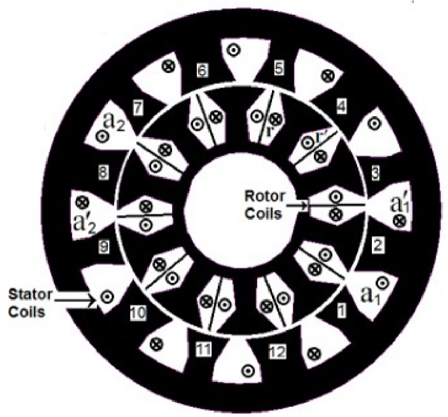
Figure 1: Cross section of 12/10 ISRM.
When a phase of the ISRM is excited, magnetic fluxes are induced within the back iron of the stator, rather than the back iron of the rotor. This induction occurs due to the magneto-motive force (mmf) orientation of the stator and rotor coils, resulting in the creation of a short flux path. Interestingly, exciting any given phase of the ISRM also induces electrical current in the rotor coils while the rotor is in motion. This phenomenon prevents flux lines from entering the rotor’s back iron, thereby establishing a short flux path.
The switching pattern employed by the ISRM closely resembles that of conventional SRMs. During the motoring mode of operation, electromagnetic torque is generated as the magnetic circuit seeks to minimize reluctance. This mechanism allows the ISRM to efficiently convert electrical energy into mechanical motion, making it a viable option for various applications requiring precise torque control and high performance.
By capitalizing on the unique characteristics of induction and reluctance principles, the ISRM offers a novel approach to achieving superior torque production and operational efficiency. Its ability to manipulate magnetic fluxes and optimize flux paths contributes to its effectiveness in generating torque while minimizing energy losses. As research and development in this field continues to advance, the ISRM holds promise as a versatile and sustainable solution for powering a wide range of machinery and systems.
| Stator Outer Radius | 115 mm |
| Stack length | 150 mm |
| Motor length including end windings | 200 mm |
| Number of stator teeth | 12 |
| Number of rotor teeth | 10 |
| Maximum current | 250 A |
| DC Voltage | 600 V |
| Stator turn numbers | concentrated / 30 |
| Rotor turn numbers | concentrated / 30 |
| Stator Outer Radius | |
| Stack length | 150 mm |
| Motor length including end windings | 200 mm |
| Number of stator poles | 12 |
| Number of rotor poles | 10 |
| Maximum current | 250 A |
| DC Voltage | |
| Number of turns per phase | 30 |
B. Torque characteristics and efficiency of ISRM
To analyze and compare the torque behavior and performance of ISRM and interior permanent magnet machine (IPM), we developed two-dimensional finite element (FE) models of the ISRM and IPM using the parameters listed in Tables 1 and 2. These parameters were selected based on those of an IPM, specifically designed for EV applications [16]. Figure 2 depicts the 12 teeth/10 pole IPM, which utilizes a concentrated winding method to enhance its performance. Using this approach, we can evaluate the torque characteristics of the ISRM and assess its suitability for various applications, particularly in electric vehicle propulsion systems. This comprehensive analysis provides valuable insights into the ISRM’s operational efficiency and potential performance enhancements, contributing to advancements in electric motor technology and sustainable transportation solutions.
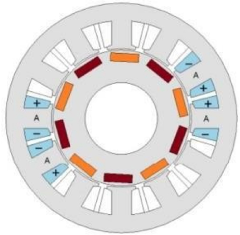
Figure 2: The 12 teeth/10 pole IPM.
The two motors model were meshed using a structured grid to balance accuracy and computational efficiency, with simulations completed in a reasonable timeframe. Simplifications, such as neglecting axial variations and assuming symmetry, were made to focus on key electromagnetic behaviors. While these assumptions may not fully capture 3D interactions and windings end effects, the 2D model is considered acceptable for analyzing these electric machines. The motor models were meshed using triangular elements to ensure accuracy and computational efficiency. The mesh was refined in critical regions such as the airgap and pole tips, with element sizes smaller than 0.4 mm, while coarser meshes with element sizes up to 2 mm were used in the shaft and other less critical areas. The total number of elements in the models was approximately 60,000, determined based on a mesh convergence study to balance precision and computational time. This mesh distribution optimized both the accuracy of the electromagnetic analysis and the simulation efficiency.
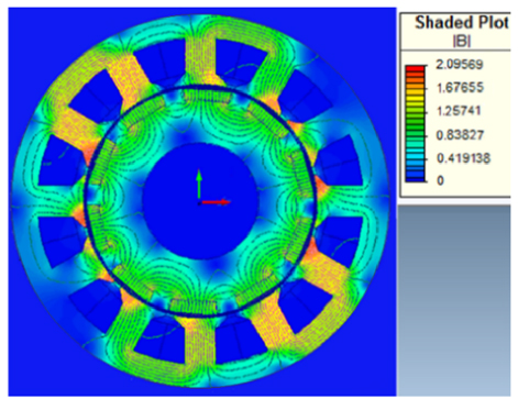
Figure 3: Flux distribution in the IPM.
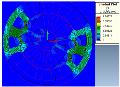
Figure 4: Flux distribution in the ISRM.
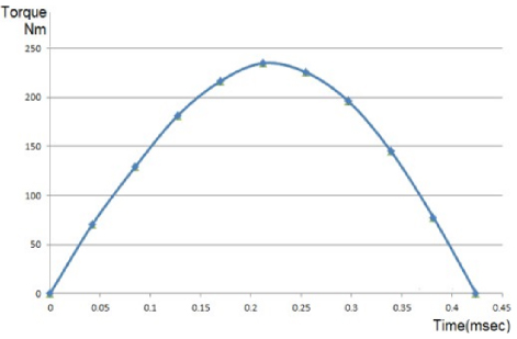
Figure 5: Torque of the ISRM at 6000 RPM.
The flux distribution and torque characteristics of the ISRM and IPM are determined through the solution of the 2D FE model. The flux distribution of the IPM is presented in Fig. 3. In Fig. 4, the flux distribution within the ISRM is shown when phase “a” is energized, revealing the achievement of a short flux path. Figure 5 showcases the torque behavior of the ISRM at various time intervals, maintaining a constant speed (6000 RPM) under single-phase excitation (100 A). As the rotor position transitions from an unaligned position to an aligned position (within an 18-degree region), the torque output is depicted. By sequentially energizing the stator phases, a familiar pattern emerges similar to a conventional SRM: a counterclockwise excitation among stator phases yields clockwise motion, and vice versa. This observation underscores the consistency between ISRM and conventional SRM operation, providing valuable insights into the machine’s torque production and motion characteristics for further analysis and optimization.
The comparative graph in Fig. 6 illustrates the average torque outputs of two motors at 3000 RPM for varying phase currents. At lower phase currents, the IPM motor demonstrates higher average torque compared to the ISRM motor. However, as the phase current increases, the ISRM motor begins to exhibit higher average torque outputs compared to the IPM motor. This shift in torque superiority from IPM to ISRM becomes more pronounced at higher phase currents. This observed phenomenon can be attributed to the more aggressive action of the induction phenomena at higher currents in the ISRM motor. As the phase current increases, the induction effects become more pronounced, enabling the ISRM motor to generate higher torques compared to the IPM motor under such conditions. The comparative graph in Fig. 7 at 6000 RPM follows a similar trend to the graph at 3000 RPM, showcasing the average torque outputs of ISRM and IPM motors for varying phase currents.
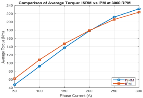
Figure 6: Average torque of ISRM vs IPM at 3000 RPM.
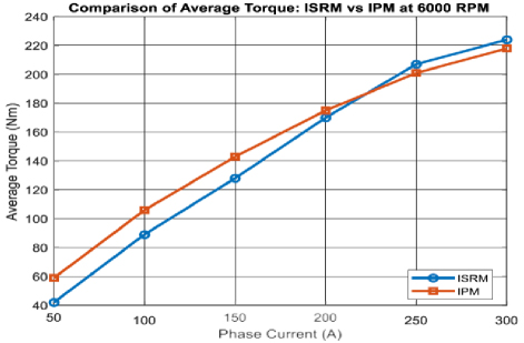
Figure 7: Average torque of ISRM vs IPM at 6000 RPM.
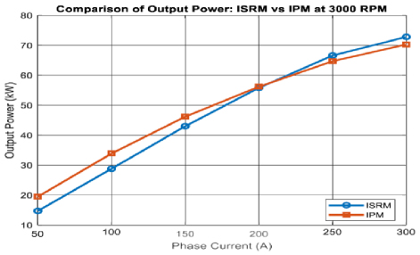
Figure 8: Output power of ISRM vs IPM at 3000 RPM.
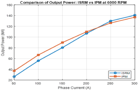
Figure 9: Output power of ISRM vs IPM at 6000 RPM.
Figures 8 and 9 illustrate a comparison of the output power between ISRM and IPM motors at 3000 RPM and 6000 RPM for varying phase currents respectively. As it is evident from the figures, the trend of output power follows a similar pattern to that of output torque across both 3000 and 6000 RPM, showing an increase with higher phase currents for both ISRM and IPM motors. Based on the results, it is understood that ISRM has higher torque density and higher power density compared to IPM at high currents.
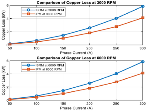
Figure 10: Copper loss of ISRM vs IPM.
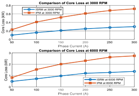
Figure 11: Core loss of ISRM vs IPM.
Figure 10 shows a comparison of copper loss between ISRM and IPM at speeds of 3000 and 6000 RPM, with different phase currents. At both speeds, ISRM consistently has more copper loss compared to IPM across various phase currents. This is because ISRM has windings on the rotor, causing higher ohmic losses within the rotor winding and resulting in more copper loss. In contrast, IPM motors don’t have windings on the rotor, so they don’t have the same kind of losses.
Figure 11 depicts a comparison of core losses between ISRM and IPM at both 3000 and 6000 RPM for different phase currents. At both speeds, ISRM consistently demonstrates lower core losses compared to IPM across various phase currents. This disparity can be attributed to the distinct design characteristics of each motor type. ISRM motors typically feature a shorter flux path, which results in a more concentrated magnetic field and consequently lower core losses compared to IPM motors .
Figure 12 depicts a comparison of efficiency between ISRM and IPM at both 3000 and 6000 RPM for different phase currents. At 3000 RPM, the efficiency of the IPM motor tends to be higher compared to the ISRM motor, specially at high currents. However, at lower currents, the efficiency of ISRM becomes closer to that of IPM. This is attributed to the fact that at lower speeds, the influence of core loss is relatively minimal, and the IPM motor benefits from its lower copper loss. However, as the speed increases to 6000 RPM, a different trend emerges. The ISRM motor exhibits higher efficiency levels at this higher speed range. This change in efficiency can mainly be credited to the much lower core loss of the ISRM motor compared to the IPM motor at 6000 RPM. At higher speeds, the core loss becomes more pronounced, favoring the ISRM motor, which is designed with a shorter flux path, resulting in lower core losses. Therefore, while the IPM motor may have an initial advantage at lower speeds, the ISRM motor demonstrates superior efficiency performance at higher speeds, making it a favorable choice for applications demanding high-speed operation.
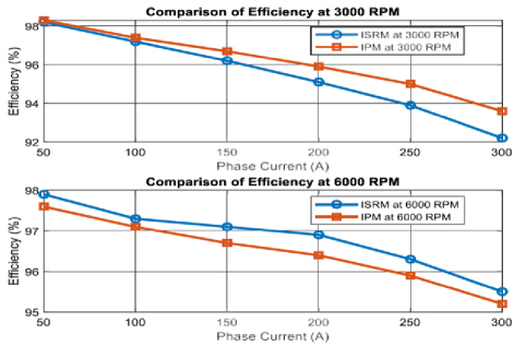
Figure 12: Efficiency of ISRM vs IPM.
III. CONCLUSION
The ISRM represents a novel advancement in electrical machine technology, offering high torque and power density. By optimizing the flux path through the use of short-circuit windings on the rotor, the ISRM achieves efficient electromechanical energy conversion, resulting in superior torque density and reduced core loss compared to other electrical machines. In this paper, a 12/10 ISRM tailored specifically for EV applications was presented and analyzed using a 2D FE model. The results indicate that the proposed ISRM geometry outperforms IPM in terms of torque and efficiency at high speeds and currents. However, it is noteworthy that ISRM exhibits lower torque capability and lower efficiency compared to IPM at lower speeds and currents. This study underscores the potential of ISRM to meet the demands of the automotive industry for high-efficiency electric propulsion systems, particularly at high speeds and currents. The future plan involves prototyping a real ISRM and testing its performance in real-world conditions to evaluate its efficiency and reliability.
REFERENCES
[1] L. Liu, Y. Huang, M. Zhao, and Y. Ruan, “Parametric modeling and optimization of switched reluctance motor for EV,” Applied Computational Electromagnetic Society (ACES) Journal, vol. 37, no. 9, p. 948, 2022.
[2] A. Infantraj and M. S. Kumaran, “Evaluation and classification of stator turn-to-turn faults using electrical equivalent circuits for surface permanent magnet brushless direct current motors,” Journal of Power Electronics, vol. 23, no. 9, pp. 1703-1711, 2023.
[3] S. Choi, W. Lee, and A. Kang, “Accuracy improvement of maximum torque per ampere control for interior permanent magnet synchronous motor drives reflecting PM flux linkage variations,” Journal of Power Electronics, vol. 23, no. 9, pp. 1678-1687, 2023.
[4] L. Liu, P. Luo, and J. Zhao, “Sensorless initial position estimation strategy for PMa-SynRM drives based on dual rotating high-frequency signal injection,” Journal of Power Electronics, vol. 23, no. 9, pp. 1745-1755, 2023.
[5] T. J. E. Miller, Electronic Control of Switched Reluctance Machines, New York: Reed Educational and Professional, pp. 227–245, 2001.
[6] L. Kadi, A. Brouri, A. Ouannou, and K. Lahdachi, “Modeling and determination of switched reluctance machine nonlinearity,” in 2020 IEEE Conference on Control Technology and Applications (CCTA), Montreal, QC, Canada, pp. 898-902, 2020.
[7] T. Andre Dos Santos Barros, P. J. Dos Santos Neto, M. V. De Paula, A. B. Moreira, P. S. N. Filho, and E. R. Filho, “Automatic characterization system of switched reluctance machines and nonlinear modeling by interpolation using smoothing splines,” IEEE Access, vol. 6, pp. 26011-26021, 2018.
[8] L. Ge, N. Du, J. Song, J. Zhang, Z. Fan, D. Zhang, and S. Song “Advanced technology of switched reluctance machines in more electric aircraft: A review,” IEEE Transactions on Power Electronics, vol. 40, no. 1, pp. 195-216, Jan. 2025.
[9] L. Liu, Y. Huang, M. Zhao, and Y. Ruan, “Parametric modeling and optimization of switched reluctance motor for EV,” Applied Computational Electromagnetic Society (ACES) Journal, vol. 37, no. 9, p. 948, 2022.
[10] B. Khan, F. Khan, W. Ullah, M. Umair, and S. Hussain, “Slot filling factor calculation and electromagnetic performance of single phase electrically excited flux switching motors,” Applied Computational Electromagnetic Society (ACES) Journal, vol. 35, no. 8, pp. 922-928, 2020.
[11] M. Abbasian, M. Moallem, and B. Fahimi, “Double stator switched reluctance motors: Fundamentals and magnetic force analysis,” IEEE Transactions on Energy Conversion, vol. 25, no. 3, pp. 589–597, 2010.
[12] M. Popescu, D. Staton, A. Boglietti, D. Hawkins, and J. Goss, “Modern heat extraction systems for electrical machines – A review,” IEEE Transactions on Industry Applications, vol. 52, no. 3, pp. 2167–2175, 2016.
[13] M. Abbasian, “Induction switched reluctance motor,” U.S. Patent 20170370296A1, 30 June 2020.
[14] M. Azamian, M. Abbasian, and D. Gerling, “Preliminary evaluation of Induction switched reluctance motor for electric vehicle application,” IEEE Access, vol. 10, pp. 26693-26701, 2022.
[15] A. Madanimohammadi, M. Abbasian, M. Delshad, and H. Saghafi, “Electromagnetic and thermal analysis of a 6/4 induction switched reluctance machine for electric vehicle application,” Applied Computational Electromagnetics Society (ACES) Journal, vol. 38, no. 5, p. 361, 2022.
[16] G. Dajaku, H. Hofmann, F. Hetemi, X. Dajaku, W. Xie, and D. Gerling, “Comparison of two different IPM traction machines with concentrated winding,” IEEE Transactions on Industrial Electronics, vol. 63, no. 7, pp. 4137-4149, 2016.
BIOGRAPHIES

Mohsen Daneshi was born in Isfahan, Iran, in 1988. He is a Ph.D. student in power engineering. Since 2013 he has been working at the Isfahan Electricity Distribution company. His research interests include electric motors, drive and renewable energy.

Mohammadali Abbasian received the bachelor’s degree, M.Sc. degree, and Ph.D. degree in Electrical Engineering from Isfahan University of Technology. From 2017 to 2018, he was with the Bundeswehr University, Munich, Germany, as a research scientist. He was an assistant professor at the IAU University, Khorasgan, Isfahan, Iran. His research area is Electrical Machines and Drives.
Majid Delshad was born in Isfahan, Iran, in 1979. He received the B.S and M.S degrees in electrical engineering in 2001 and 2004 from Kashan University and Isfahan University of Technology, Iran, respectively. He received the Ph.D. degree in electrical engineering in Isfahan University of Technology. He is associate professor in Isfahan (Khorasgan) Branch, IAU. His research interest includes soft switching techniques in DC-DC converters and current-fed converters.
ACES JOURNAL, Vol. 40, No. 1, 62–68
doi: 10.13052/2025.ACES.J.400108
© 2025 River Publishers