Low SAR-UWB Rectangular Microstrip Magnetic Monopole Antenna for S-Band and Biomedical Applications
Chemseddine Zebiri, Samira Mekki, Djamel Sayad, Issa Elfergani, Mohamed Lamine Bouknia, Rami Zegadi, Atul Varshney, and Jonathan Rodriguez
Laboratoire d’Electronique de Puissance et Commande Industrielle (LEPCI)
Department of Electronics, University of Ferhat Abbas, Setif 1, 19000 Setif, Algeria
czebiri@univ-setif.dz, samira.mekki@univ-setif.dz, ml.bouknia@univ-setif.dz, ramizegadi@univ-setif.dz
Laboratoire d’Electronique de Skikda (LRES)
Department of Electrical Engineering, University of 20 Aout 1955-Skikda, 21000, Skikda, Algeria
d.sayad@univ-skikda.dz
Instituto de Telecomunicações
Campus Universitário de Santiago 3810-193 Aveiro, Portugal
i.t.e.elfergani@av.it.pt, jonathan@av.it.pt
Faculty of Engineering and Informatics
University of Bradford, Bradford, UK
Electronics and Communication Engineering Department
FET, Gurukul Kangri (Deemed to be) University, Uttarakhand, India
atulgkvright@gmail.com
Submitted On: August 8, 2024; Accepted On: February 18, 2025
ABSTRACT
The development of low specific absorption rate (SAR) antennas is crucial for safety and efficiency in wireless communication and biomedical applications. This study introduces a low SAR ultra-wideband (UWB) rectangular microstrip monopole antenna with an extended ground plane. The design operates effectively in free space and on a human body phantom. It achieves a reflection coefficient of -42.59 dB at 2.48 GHz and covers the S-band from 2.31 GHz to 4.12 GHz with a peak gain of 5.09 dBi in free space. The antenna maintains consistent performances when placed on a human phantom. With reverse and front patch faces, its gain improves to 5.53 dBi and 5.80 dBi, respectively. Experimental validation of the fabricated prototype shows excellent agreement with simulations conducted using high-frequency structure simulators (HFSS) and advanced design systems (ADS). Additionally, lumped-element equivalent circuits are used to analyze impedance behavior in both environments, confirming the antenna’s robustdesign.
Index Terms: Biomedical, human phantom model, ISM band, low SAR, RLC-equivalent circuit, S-band, UWB monopole antenna.
I. INTRODUCTION
Recently, in advanced biomedical applications, planar microstrip antennas have gained significant importance. The planar microstrip antennas are widely used for human in-body (ingestible antennas), on-body (implantable antennas) and off-body (textile or wearable antennas) wireless communication devices. They enable physiological information monitoring and disease diagnosis and provide treatment for patients through wireless telemetry [1]. Moreover, ongoing research on implantable medical devices, such as endoscopy [2], neural recording [3] and blood glucose monitoring [4], has further propelled the importance of planar antennas in biomedical applications. Wearable wireless communication systems, such as body area networks (BANs), are constantly in need of lightweight, compact, flexible, low-profile and durable designs ensuring comfort and ease of use for the wearer [5]. Ultra-wideband (UWB) monopole microstrip antennas play a vital role in meeting system requirements and the linked budget necessities of BAN devices [5–6], medical telemetry applications [7], microwave imaging systems [8] and others [9–12].
Since the human body is a lossy platform for electromagnetic (EM) wave propagation, the efficiency and insensitivity of the antenna to the proximity effect of the human body must be maximized to ensure its reliability and effectiveness [13].
In general, the radiation efficiency of an omnidirectional antenna decreases dramatically when placed close to the human body. To minimize the impact on the human body and reduce the body’s exposure to electromagnetic radiation, an antenna with a unidirectional radiation pattern is a good choice. It should be insensitive to the proximity effect and should have the least amount of radiation towards the human body [14]. Special design considerations are necessary to meet the requirements of minimizing potential harm to human tissue, particularly by maintaining a minimum specific absorption rate (SAR) of radiation [15]. Many antennas for 2.4 GHz ISM band and biomedical applications have been reported in the literature [5, 6, 16–20]. Most of these antennas exhibit a narrow bandwidth characteristic as well as complex designs. Elshaekh et al. [21] present a design for implantable biomedical devices featuring two distinct integrated antennas on a single chip. The design objective is to handle different tasks: a sensing multi-band meander line antenna for data communication and a wideband dipole antenna for RF energy harvesting. The challenges of signal loss due to human tissue and enhancing device functionality are addressed. Both antennas are fabricated using UMC180nm CMOS technology on a 0.55 mm chip. This antenna system offers high data rates and reduced radiation exposure compared to traditional imaging techniques. This separation simplifies circuit design and improves efficiency by avoiding interference between functions.
Some research works have explored wearable antennas for medical monitoring, revealing ongoing challenges in their design. This area has experienced a notable surge in interest recently. Innovations include a button-shaped wearable antenna and an L-shaped PIFA developed for e-health applications [22]. Additionally, in [23], a UWB-printed antenna tailored for monitoring cardiac activity is addressed.
The rising costs of healthcare for aged population and limited access to medical services highlight the need for telemedicine and ongoing remote patient monitoring. Traditional methods for measuring respiration, using ECG and other wearable devices, tend to be expensive and intrusive, potentially altering natural breathing patterns and leading to inaccurate readings. These devices often restrict patient movement with wired connections and are limited in their ability to provide continuous, long-term monitoring, especially for chronic conditions like stroke. In contrast, non-contact RF radar sensors offer a cost-effective, comfortable and low-power alternative for healthcare applications. These sensors, which detect small physiological movements like respiration and heartbeat through Doppler shifts, have been in use since the 1970s. Beyond their medical applications, radar systems are also employed for search and rescue, security and indoor fall detection. Recently, radar technology has been adapted for precise respiration measurement in cancer radiotherapy. Mpanda et al. [24] developed a low-cost, compact Doppler-based system at 2.4 GHz for non-contact vital signs monitoring. This continuous-wave radar system was compared with traditional contact-based devices to evaluate its performance. The study focused on heart rate and respiration signals, revealing that a dipole array antenna outperforms both a 21 patch array antenna and Yagi-Uda antennas. Due to its advantageous characteristics, including lightweight, compact design and cost-effectiveness, the dipole array antenna emerges as a superior choice for integrating into medical devices for vital signs monitoring. Varshney et al. [25, 26] fabricated and tested modified circular patch antennas at 2.45 GHz with wide bandwidth and good gain. However, they exhibit big size issues in the ISM band. In biomedical and ISM band applications, compact size is highly desirable and challenging.
Neebha et al. [27] designed a compact C-shaped narrow band antenna using artificial transmission line theory and extracted the RLC electrical equivalent circuit using the transmission line method at 2.4 GHz. The proposed antenna achieves a 77.55% fractional bandwidth from 2.33 GHz to 2.52 GHz with a gain value of 2.1 dBi. Varshney et al. [28] designed a 22 MIMO antenna for the 5G n78 band and extracted the electrical equivalent circuit using the antenna structure.
Research Gap: The antenna compact size results in a narrow bandwidth at 2.45 GHz when a full ground is used. However, as the ground length decreases, the -10dB bandwidth becomes wider [25, 26]. Achieving high gain with wide bandwidth is always challenging. The miniaturization of the antenna size at lower frequencies presents an additional challenge. Furthermore, to control the SAR value within the government-specified limits is another emerging challenge.
A. Research objectives
The following are the objectives of the proposed research.
Design of a miniaturized UWB antenna with a gain higher than 5dBi and low SAR for biomedical applications.
Analysis of the design performances in free space as well as on the human body in reverse and front face study cases.
A further aim of this study is to extract the antenna RLC electrical equivalent circuits in free space and on-body configurations (with reverse and front face cases) and compare their results to validate the antenna performance.
B. Contribution and novelty
This work presents a wideband antenna with a peak gain higher than 5 dBi. Additionally, the electrical RLC equivalent circuit is extracted using advanced design system (ADS) software for three configurations: the antenna is considered in free space, placed on the human body with antenna patch side on the skin (reverse face) and placed on the human body with the antenna ground side on the skin (front face). The low SAR values in each case have been evaluated, they fall under government-specified limits.
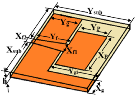
Figure 1: Proposed antenna with trapezoidal-feed and extended L-shaped ground plane.
Table 1: Dimensions of the proposed patch antenna
| Parameter | Value (mm) | Parameter | Value (mm) | Parameter | Value (mm) |
| Y | 11 | X | 34 | X | 2 |
| X | 18 | Y | 28 | Y | 12.54 |
| Y | 12.54 | Y | 10.5 | Y | 17.5 |
| X | 4 | X | 6 | h | 1.58 |
Details of the antenna design, using high-frequency structure simulator (HFSS), are described, and simulated results, such as reflection coefficient in free space and on the human body, and specific SAR are presented, measured and analyzed.
II. ANTENNA CONFIGURATION
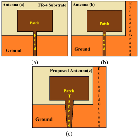
Figure 2: Step-by-step antenna design development.
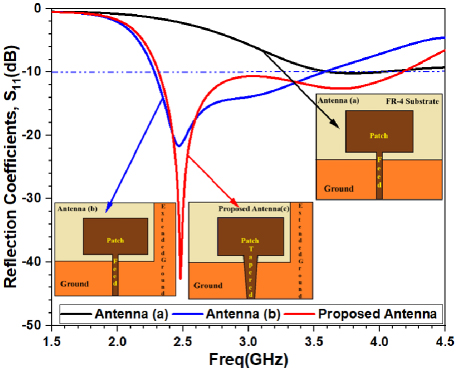
Figure 3: Reflection coefficient (S) of antenna design development (step-by-step).
The proposed antenna is a microstrip monopole antenna with an extended ground plane printed on an FR-4 substrate with a thickness of h 1.58 mm, a relative dielectric permittivity of 4.4 and a loss tangent of 0.002. A trapezoidal-shaped microstrip feed line is used to excite the antenna for better impedance matching. The rectangular radiating patch has dimensions of 3428 mm. The antenna is optimized to meet the ISM band requirements at 2.48 GHz. The optimized design dimensional parameters are illustrated in Fig. 1 and displayed in Table 1.
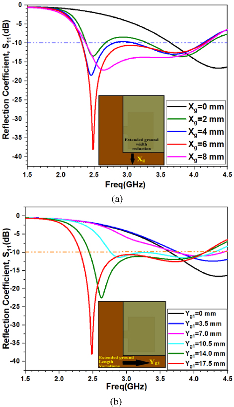
Figure 4: Effect of the ground geometrical parameters on S (a) width X and (b) length Y
A. Parametric study
The proposed antenna is first designed as an edge fed monopole rectangular patch antenna as shown in Fig. 2 (a). The ground plane is then extended in an L-shaped form (Fig. 2 (b)) and finally, the feed line is made trapezoidal (a total tapering of 2 mm from antenna port to antenna edge) as illustrated in Fig. 2 (c). The reflection coefficients (S) of all the antenna design steps are presented in Fig. 3.
It can be noticed, from Scomparisons, that the L-shaped extended ground plane improves the reflection coefficient below -10 dB and tunes the antenna at 2.48 GHz. The trapezoidal feed line excellently improves the impedance matching and reduces the reflection coefficients well below -10 dB at resonance frequency 2.48 GHz.
The extended ground plane width (X) and length (Y) variation effects are shown in Fig. 4 (a,b). X is changed in a step size of 2 mm and Y is varied in a step size of 3.5 mm. The extended ground’s width helps to improve impedance matching while its length helps to tune the resonance frequency close to the desired frequency 2.5 GHz. The effect of X and Y on the reflection coefficient are represented in Fig. 4.
B. Human tissue model properties
The proposed antenna, with the desired resonance frequency at the ISM band (2.4-2.4835 GHz), is now imbedded on a 5050 mm human tissue for test. It consists of three different layers: skin, fat and muscle. The thicknesses and dielectric properties of the human tissue for the proposed antenna are given in Table 2 [29, 30]. The antenna size is very convenient for the human tissue with antenna resonance. In this research, the antenna is placed on the body in two ways: the antenna ground is in contact with the body (Case 1: reverse Face1) and the antenna patch is in contact with the body (Case 2: front Face2) as shown in Fig. 5.
Table 2: Human tissue layers and their thicknesses[29, 30]
| Human Tissue | Thickness(mm) | Conductivity (S/m) | Relative Permittivity () |
| Skin | 4 | 1.46 | 38 |
| Fat | 4 | 0.10 | 5.28 |
| Muscle | 8 | 1.73 | 52.7 |
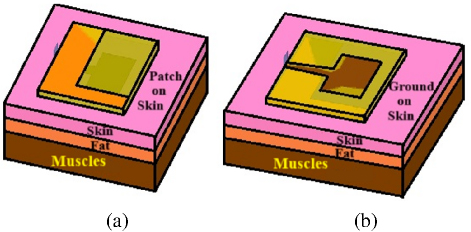
Figure 5: Antenna placement on the human body phantom model: (a) Case 1 and (b) Case 2.
III. ANTENNA SIMULATION RESULTS AND VALIDATION
The proposed antenna is initially designed and simulated in free space. Subsequently it is evaluated on the body in Case 1 and Case 2 configurations. The S in the free space case shows an ultra-wide bandwidth of 73% fractional bandwidth ranging from 2.30 GHz to 4.125 GHz covering the full ISM band and resonating at around 2.5 GHz (Fig. 6). It can be noticed that human tissue significantly impacts the antennas behavior, altering the S peaks and bandwidth. Case 1 most affects the frequency response of the antenna which shifts the frequency band backward resulting in a wider bandwidth. The antenna response is slightly affected in Case 2 configuration with a better impedance matching at higher frequencies. Additionally, in both cases, the antenna preserves its UWB characteristic. The S plots drop below -10 dB and their corresponding bandwidths become slightly wider compared to the free-space case.
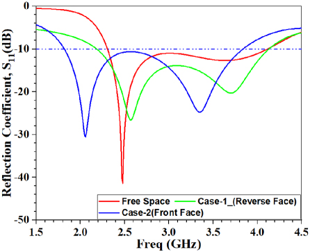
Figure 6: Reflection coefficients (S) of the proposed antenna.
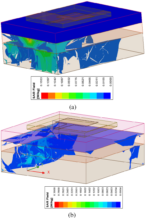
Figure 7: Antenna 1g SAR at 2.4 GHz (a) Case 1 and (b) Case 2.
The effect of electromagnetic exposure on the human body has been studied in terms of SAR at 2.4 GHz. Corresponding results are presented in Fig. 7. It can be observed that the maximum SAR value in both cases is very low. It is well below the FCC/IC limit of 1.6 W/kg (1 g) and the EU limit of 2.0 W/kg (10 g) across the active bandwidth [31].
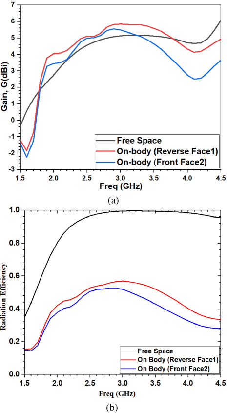
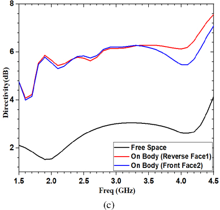
Figure 8: Proposed antenna performance parameters: (a) gain, (b) radiation efficiency and (c) directivity.
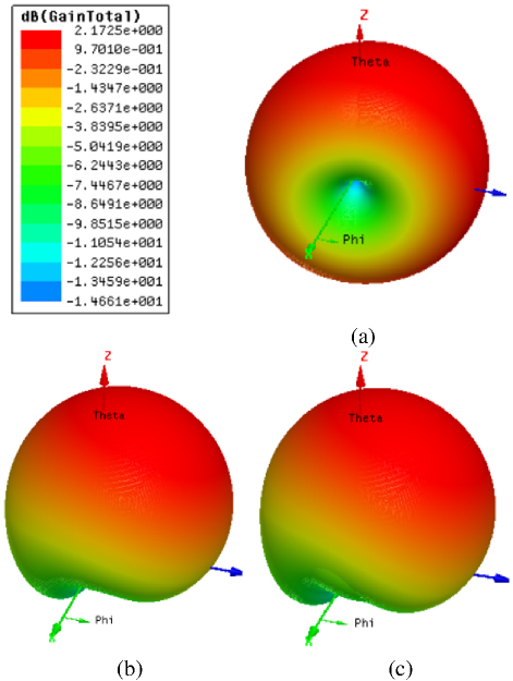
Figure 9: Gain 3D plot of the proposed antenna: (a) free space, on-body (b) Case 1 and (c) Case 2.
The proposed antenna gains in free space and on-body have been evaluated and compared in Fig. 8 (a). It can be observed that the gain of the antenna is improved when it is placed on the body. The peak gain achieved by the antenna in all three cases are higher than 5 dBi. The highest value of the peak gain 5.80 dBi is achieved when the antenna patch touches the body (reverse face). The radiation efficiency, gain and directivity of the proposed antenna simulated in free space and on-body (Cases 1 and 2) are presented in Fig. 8. According to these results, the antenna exhibits the same gain value [Fig. 8 (a)], however, its efficiency decreases by 50% when placed near the human body [Fig. 8 (b)]. Since omnidirectional antennas radiate energy uniformly in every direction of a plane, lower directivity results since power is spread over a big area. While single-plane antennas can concentrate energy into narrower beams, higher directivity has been achieved by the power that is radiated in one direction rather than spreading in all directions. The radiation resistance of a half-wavelength dipole is R 73 , and the maximum directivity is 1.64. For a quarter-wavelength monopole, the radiation resistance is 73/2 [32]. As a result, the directivity is multiplied by two as shown in Fig. 8 (c).
The antenna 3D gain plot in free space at 2.45 GHz is depicted in Fig. 9 (a). In free space, the antenna exhibits an omnidirectional radiation pattern. However, when the antenna is placed on the human body, the body acts as a reflector. This alters the radiation pattern of the antenna. Considering all the factors mentioned, it becomes evident that the radiation pattern, as illustrated in Figs. 9 (b-c), improves antenna directivity and is the primary factor responsible for affecting radiation efficiency.
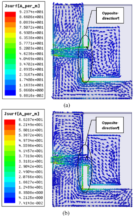
Figure 10: Surface current density distribution of the proposed antenna at 2.4 GHz: (a) front Face1 (b) reverse Face2.
According to the surface current distributions shown in Fig. 10 and the E- and H-field distributions presented in Fig. 11, the proposed antenna can be qualified as a magnetic dipole. A magnetic dipole antenna is characterized by two parallel wires of equal lengths, fed with alternating current in opposite phases [33]. By examining Fig. 11 (a), it is evident that the normal component of the electric field is significantly weaker compared to the tangential component H-field depicted in Fig. 11 (b). This disparity in field strengths helps to explain the resulting low SAR. Additionally, it is important to note that biological tissues possess a high dielectric constant, which acts as a reflector. Consequently, the normal components of the E-field are reflected in free space, as illustrated in Fig. 11 (a).
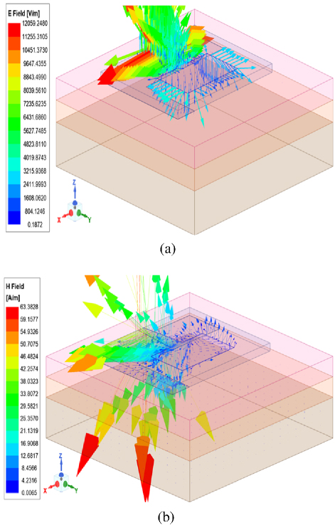
Figure 11: Field distribution of the proposed antenna at 2.4 GHz: (a) E-field and (b) H-field.
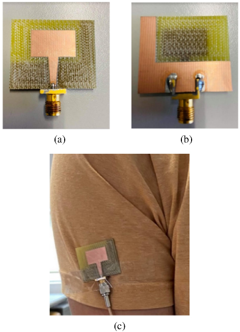
Figure 12: Prototype of the proposed antenna: (a) top face, (b) bottom face and (c) on-body (Case 2).
A prototype antenna (Fig. 12) is fabricated and measured to validate the simulation results. The reflection coefficient (S) in free space and on the human body, for both cases, is measured at 2.4 GHz. The simulated and measured reflection coefficient of the proposed antenna in free space and on the body are illustrated in Fig. 13. The simulated and measured results are found to agree well within the operating band.
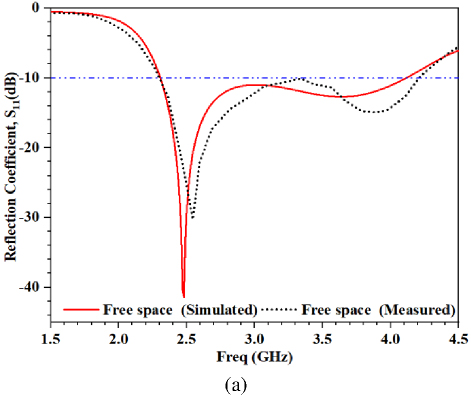
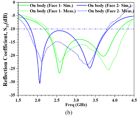
Figure 13: Simulated and measured S in (a) free space and (b) on-body (Case 1 and Case 2).
IV. EQUIVALENT CIRCUIT ANALYSIS
The RLC resonator model is commonly used to model microwave sensors and radiating antennas [34, 35]. Various studies have developed equivalent circuits for resonant antenna structures, such as Chu’s [36] dipole antenna circuit. To avoid the complexity of calculating the total electric energy in the capacitances of the equivalent circuit, Chu approximates it using a simple series RLC circuit. The values of these components are determined by equating the resistance, reactance and the derivative of reactance with those of the series RLC circuit [36]. Recent research works have also focused on antenna design using electrical circuits. They often compare commercial software results with electrical models through S-parameters [34].
In the field of antenna design, a radiating structure is represented by an RLC electrical equivalent circuit model (ECM). To accurately characterize the radiator’s behavior, the circuit elements (R, L and C) must be precisely derived. Many studies [35] propose lumped equivalent circuit models based on S-parameter amplitudes; however, these models often fail to provide precise RLC values, leading to an incomplete understanding of the radiator’s behavior within the operating band.
This study differs by deriving the RLC components from complex-valued impedance parameters obtained through ADS simulations, validated against HFSS results. This approach enables better differentiation between resonant modes, such as radiating, non-radiating and adaptation modes. The proposed antenna’s RLC equivalent circuit is modeled as a parallel combination of impedances [28, 34, 35], with circuit models for free space and on-body scenarios (Case 1 and Case 2) shown in Figs. 14 and 15.
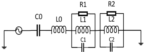
Figure 14: Equivalent circuit model of the proposed UWB antenna in free space.
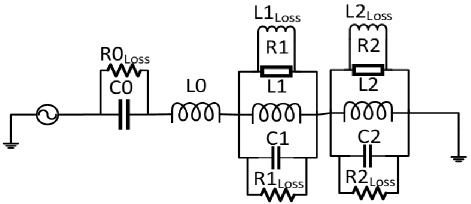
Figure 15: Antenna equivalent circuit model on the human body (Case 1 and Case 2).
Furthermore, it is commonly accepted in the literature that UWB applications can be modeled such that each resonant mode is represented by a parallel RLC component [37, 38]. This modeling strategy captures the interactions of multiple adjacent resonant circuits within UWB antennas, effectively characterizing their input impedance characteristics. Since our work involves UWB applications with two distinct resonant modes, we represent these modes using two parallel blocks of RLC components. Understanding how equivalent circuit models adapt to different environments, such as off- and on-body, is key to analyzing antenna behavior.
A. In free space
The antenna’s equivalent circuit features two parallel RLC blocks R1, L1, C1 and R2, L2, C2, starting with capacitors Cand inductance L0. The antenna’s physical dimensions and geometry as well as its operating frequency determine these inductances. The circuit model includes resistors that account for losses due to radiation and material imperfections and capacitors that represent the antenna’s ability to store electric energy. This parallel configuration allows for multiple resonant modes within the antenna.
B. On human body Case 1
Where the antenna is in direct contact with the human body, the equivalent circuit model effectively captures this direct interaction with the lossy medium. The configuration comprises two parallel RLC blocks R1, L1, C1 and R2, L2, C2, with capacitors C0 in parallel with a shunt resistor R0and inductance L0. In this model, resistors R1 and R2 are positioned in parallel with their respective lossless inductances L1 and L2.
C. On human body Case 2
While the same configuration applies on human body Case 2, where the antenna is not in direct contact with the body, the values of these components will be fine-tuned based on performance metrics such as input impedance and return loss under varying conditions. This adjustment is crucial for optimizing the antenna’s performance when coupled to the human body, ensuring effective energy transfer while minimizing losses due to tissue absorption. The equivalent circuit model provides a more accurate representation of antenna behavior when placed on or near the human body. By incorporating these parallel blocks, it allows for an analysis of how different resonant modes interact and how both the antenna’s characteristics and its environment influence them. The inclusion of lossless inductances and shunt resistors simulates energy dissipation in a lossy medium while maintaining an accurate depiction of critical resonant frequencies necessary for effective operation in UWB applications.
Table 3: Element values of the equivalent circuit model in free space, on-body (Case 1) and on-body (Case 2)
| Components | Free Space | On-body (Case 1) | On-body (Case 2) |
| R1 () | 75 | 49 | 74 |
| L1 (nH) | 0.746 | 0.973 | 1.304 |
| C1 (pF) | 6.449 | 6.129 | 4.020 |
| R2 () | 82 | 42 | 68 |
| L2 (nH) | 1.084 | 0.760 | 1.334 |
| C2 (pF) | 2.182 | 3.161 | 1.918 |
| L0 (nH) | 1.985 | 1.902 | 2.758 |
| C0 (pF) | 2.397 | 2.023 | 1.590 |
| L1 (nH) | 1808 | 30000 | |
| L2 (nH) | 20.677 | 20.507 | |
| R1 (k) | 1.500 | 37.257 | |
| R2 (k) | 5 | 2.908 | |
| R0 (k) | 5 | 2.228 |
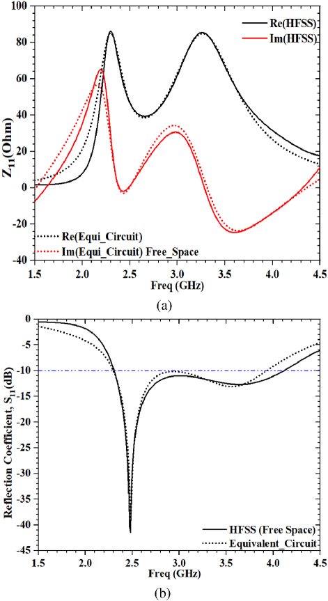
Figure 16: Simulated results compared to EM model in free space: (a) input impedance and (b) S.
When the antenna is placed on the human body (lossy medium), the equivalent circuit remains almost the same compared to the equivalent circuit in free space. Inductances L0, L1 and L2 remain the same as in free space, and when the human body is a lossy medium, the resistors R1 and R2 can be represented by lossless inductances L1 and L2, respectively, and the capacitors C0, C1 and C2 can be represented by shunt resistors R0Loss, R1Loss and R2Loss, as shown in Fig. 15 for on-body placement Case 1 andCase 2.
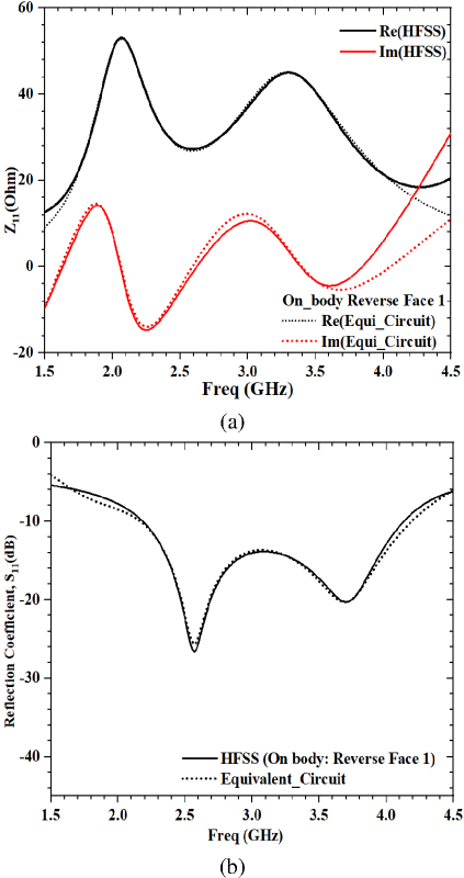
Figure 17: Simulated results compared to EM model of the proposed antenna on-body (Case 1): (a) input impedance and (b) S11.
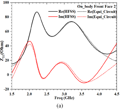
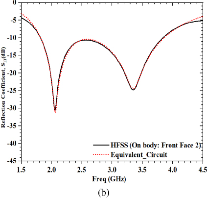
Figure 18: Simulated results compared to EM model of the proposed antenna on-body (Case 2): (a) input impedance and (b) S11.
The input impedance and reflection coefficients of the proposed antenna in free space using HFSS and equivalent circuit models using ADS are compared in Fig. 16, in Fig. 17 for Case 1 and in Fig. 18 for Case 2. Excellent agreement between the circuit model and the EM model have been achieved. The optimized elements values are shown to be very close to each other and are listed in Table 3.
Table 4 summarizes the obtained results compared with the literature at 2.4-2.5 GHz ISM band. It is clear that the proposed design shows interesting performances in terms of reduced size and low reflection, its innovative and simple structure and practical feasibility places it among the most competitive antennas.
Table 4: Comparative analysis of proposed and reference antennas
| Ref | Size (mm) | Resonating Frequencyf(GHz) | S (dB) | Gain (dBi) |
| [5] | 5016 | 2.45 | 14.2 | 1.98 On-body |
| [6] | 6243 | 2.45 | 23 | 3.01 Off-body2.11 On-body |
| [16] | 6060 | 2.4 | 25.90 | 4.66 Off-body |
| [17] | 50.3332 | 2.4 | 22 | Not Given |
| [18] | 3540 | 2.4 | 31 | Not Given |
| [19] | 5560 | 2.45 | 29.73 | 7.04 Off-body |
| [20] | 41.529 | 2.45 | 36.66 | Not Given |
| This work | 2834 | 2.48 | 42.59 | 5.80 On-body |
V. CONCLUSION
This paper presents a low SAR miniaturized microstrip UWB monopole antenna operating at 2.48 GHz for ISM band biomedical applications. The proposed antenna is fabricated and good agreement is realized between simulation and measurement results. To facilitate analysis and optimization, an RLC electrical equivalent circuit model of the antenna is developed and fine-tuned using ADS software. The proposed antenna holds significant potential for enabling safe and efficient wireless communication with the human body. Its compatibility with UWB and ISM band applications, combined with its excellent performance characteristics, make it a promising solution for future on-body communication systems.
ACKNOWLEDGMENT
This publication has received funding from the European Union’s Horizon 2020 research and innovation program under grant agreement H2020-MSCA-RISE-2018-eBorder-872878. This publication has received funding from the European Union’s Horizon Europe research and innovation program under grant agreement HE-MSCA-SE-6G-TERAFIT- 101131501. This work is also funded by the FCT/MEC through national funds and when applicable co-financed by the ERDF, under the PT2020 Partnership Agreement under the UID/EEA/50008/2020 and UIDP/50008/2020 project. This work was supported in part by the DGRSDT (Direction Générale de la Recherche Scientifique et du Development Technologique), MESRS (Ministry of Higher Education and Scientific Research), Algeria.
REFERENCES
[1] S. Ahmad, B. Manzoor, M. M. Shair, S. Khan, A. Akram, A. Ghaffar, A. J. Abdullah Al-Gburi, E. M. Ali, F. Arpanaei, and M. Alibakhshikenari, “Novel implantable antenna with miniaturized footprint size for wideband biomedical telemetry applications,” Frequenz, vol. 77, no. 5-6, pp. 293-301, 2023.
[2] S. M. A. Shah, M. Zada, J. Nasir, O. Owais, A. Iqbal, and H. Yoo, “Miniaturized four-port MIMO implantable antenna for high-data-rate wireless-capsule-endoscopy applications,” IEEE Transactions on Antennas and Propagation, vol. 71, no. 4, pp. 3123-3133, 2023.
[3] A. Sharma, E. Kampianakis, and M. S. Reynolds, “A dual-band HF and UHF antenna system for implanted neural recording and stimulation devices,” IEEE Antennas Wireless Propag. Lett., vol. 16, pp. 493-496, 2017.
[4] D. Hecht, I. Ullmann, D. Oppelt, T. Pfahler, N. Amer, and M. Vossiek, “Millimeter-wave imaging and near-field spectroscopy for burn wound assessment,” Frequenz, vol. 76, no. 11-12, pp. 661-667, 2022.
[5] I. Gil and R. Fernández-García, “Wearable PIFA antenna implemented on jean substrate for wireless body area network,” Journal of Electromagnetic Waves and Applications, vol. 31, no. 11-12, pp. 1194-1204, 2017.
[6] S. M. Ali, V. Jeoti, T. Saeidi, and W. P. Wen, “Design of compact microstrip patch antenna for WBAN applications at ISM 2.4 GHz,” Indonesian Journal of Electrical Engineering and Computer Science, vol. 5, no. 3, pp. 1509-1516, 2019.
[7] R. Bala, R. Singh, A. Marwaha, and S. Marwaha, “Wearable graphene based curved patch antenna for medical telemetry applications,” Applied Computational Electromagnetics Society (ACES) Journal, pp. 543-550, 2016.
[8] N. Ojaroudi, M. Ojaroudi, N. Ghadimi, and M. Mehranpour, “UWB square monopole antenna with omni-directional radiation patterns for use in circular cylindrical microwave imaging systems,” Applied Computational Electromagnetics Society (ACES) Journal, pp. 123-129, 2013.
[9] D. Sayad, C. Zebiri, H. Obeidat, I. Elfergani, A. Amroun, A. Palandoken, M. L. Bouknia, R. Zegadi, and J. Rodriguez, “New elliptical miniaturized antenna using concentric open rings for UWB applications,” Progress In Electromagnetics Research C, vol. 134, pp. 79-91, 2023.
[10] A. Amroun, C. Zebiri, D. Sayad, I. Elfergani, A. Desai, M. L. Bouknia, R. Zegadi, and J. Rodriguez, “Miniaturized six-ring elliptical monopole-based MIMO antenna for ultrawideband applications,” International Journal of Communication Systems, vol. 36, no. 14, p. e5557, 2023.
[11] C. Bensid, M. L. Bouknia, D. Sayad, I. Elfergani, H. Bendjedi, R. Zegadi, J. Rodriguez, A. Varshney, and C. Zebiri “Novel pentagonal-shaped monopole antenna with a CSRR metamaterial loaded defected ground for UWB applications,” Progress in Electromagnetics Research C, p. 139, 2023.
[12] Y. Tighilt, C. Bensid, D. Sayad, S. Mekki, R. Zegadi, M. L. Bouknia, I. Elfergani, P. Singh, J. Rodriguez, and C. Zebiri, “Low-profile UWB-MIMO antenna system with enhanced isolation using parasitic elements and metamaterial integration,” Electronics, vol. 12, no. 23, p. 4852, 2023.
[13] F. Benmahmoud, P. Lemaitre-Auger, and S. Tedjini, “Wearable folded planar dipole antenna: Design and assessment for on-body wireless communication devices,” IEEE Antennas and Propagation Magazine, vol. 65, no. 1, pp. 27-39, 2023.
[14] T. S. See and Z. N. Chen, “Experimental characterization of UWB antennas for on-body communications,” IEEE Transactions on Antennas and Propagation, vol. 57, no. 4, pp. 866-874, 2009.
[15] A. Lak, Z. Adelpour, H. Oraizi, and N. Parhizgar, “Design and SAR assessment of three compact 5G antenna arrays,” Scientific Reports, vol. 11, no. 1, p. 21265, 2021.
[16] G. Demirbas and A. K. A. R. Ekrem, “Design and interpretation of microstrip patch antenna operating at 2.4 GHz for wireless WI-FI application,” Avrupa Bilim ve Teknoloji Dergisi, vol. 34, pp. 672-675, 2022.
[17] M. Salim and A. Pourziad, “A novel reconfigurable spiral-shaped monopole antenna for biomedica applications,” Progress in Electromagnetics Research Letters, vol. 57, pp. 79-84, 2015.
[18] X. Guo, Y. Hang, Z. Xie, C. Wu, L. Gao, and C. Liu, “Flexible and wearable 2.45 GHz CPW-fed antenna using inkjet-printing of silver nanoparticles on pet substrate,” Microwave and Optical Technology Letters, vol. 59, no. 1, pp. 204-208, 2017.
[19] M. S. Islam, M. I. Ibrahimy, S. M. A. Motakabber, A. Z. Hossain, and S. K. Azam, “Microstrip patch antenna with defected ground structure for biomedical application,” Bulletin of Electrical Engineering and Informatics, vol. 8, no. 2, pp. 586-595, 2019.
[20] S. Sukhija and R. K. Sarin, “Design and performance of two-sleeve low profile antenna for bio-medical applications,” Journal of Electrical Systems and Information Technology, vol. 4, no. 1, pp. 49-61, 2017.
[21] D. Elshaekh, S. Kayed, and H. Shawkey, “Single-chip two antennas for MM-Wave self-powering and implantable biomedical devices,” Applied Computational Electromagnetics Society (ACES) Journal, vol. 36, no. 7, pp. 885-893, 2021.
[22] W. Huang and A. A. Kishk, “Compact antenna designs for wearable and medical portable systems,” Applied Computational Electromagnetics Society (ACES) Journal, vol. 26, no. 4, Apr. 2011.
[23] E. Pittella, P. Bernardi, M. Cavagnaro, S. Pisa, and E. Piuzzi, “Design of UWB antennas to monitor cardiac activity,” Applied Computational Electromagnetics Society (ACES) Journal, vol. 26, no. 4, pp. 267-274, Apr. 2011.
[24] R. S. Mpanda, L. Qi, Q. Liang, L. Xu, J. Shi, and L. Zhao, “Design and evaluation of typical antennas for monitoring vital signs,” Applied Computational Electromagnetics Society (ACES) Journal, pp. 497-505, 2019.
[25] A. Varshney, V. Sharma, T. M. Neebha, and N. P. Kumari, “Notch-band eliminator wideband CSRR loaded monopole fractal antenna for ISM and PCS communications,” World Journal of Engineering, vol. 21, no. 4, pp. 821-834, 2024.
[26] A. Varshney, T. M. Neebha, V. Sharma, and A. D. Andrushia, “Low-cost L-band to Ku-band frequency reconfigurable BAR64-02V controlled antenna for satellite, military, and radar applications,” IETE Journal of Research, vol. 70, no. 6, pp. 1-14, 2024.
[27] T. M. Neebha, A. D. Andrushia, P. M. Bruntha, A. Varshney, R. Manjith, and S. Dhanasekar, “On the design of miniaturized C-shaped antenna based on artificial transmission line loading technique,” Journal of Electromagnetic Waves and Applications, vol. 37, no. 6, pp. 814-826,2023.
[28] A. Varshney, V. Sharma, and A. K. Sharma, “RLC-equivalent circuit-based stub loaded 2x2 MIMO antenna for wireless applications,” Microwave Review, vol. 29, no. 1, pp. 44-54, 2023.
[29] Z. Duan, Y. X. Guo, R. F. Xue, M. Je, and D. L. Kwong, “Differentially fed dual-band implantable antenna for biomedical applications,” IEEE Transactions on Antennas and Propagation, vol. 60, no. 12, pp. 5587-5595, 2012.
[30] S. Gabriel, R. W. Lau, and C. Gabriel, “The dielectric properties of biological tissues: III. Parametric models for the dielectric spectrum of tissues,” Physics in Medicine & Biology, vol. 41, no. 11, p. 2271, 1996.
[31] J. C. Lin, “RF health safety limits and recommendations [Health Matters],” IEEE Microwave Magazine, vol. 24, no. 6, pp. 18-77, 2023.
[32] J. L. Volakis, Antenna Engineering Handbook. New York: McGraw-Hill Education, 2007.
[33] J. R. James, P. S. Hall, and C. Wood, “Microstrip antenna: Theory and design,” IET, vol. 12, 1986.
[34] S. Mekki, R. Zegadi, S. Mosbah, D. Sayad, I. Elfergani, M. L. Bouknia, J. Rodriguez, A. Desai, M. Palandoken, and C. Zebiri, “Equivalent circuit of a planar microwave liquid sensor based on metamaterial complementary split ring resonator,” Frequenz, vol. 78, no. 1-2, pp. 37-45, 2024.
[35] S. Mekki, A. Varshney, D. Sayad, I. Elfergani, H. Bendjedi, M. L. Bouknia, R. Zegadi, J. Rodriguez, M. Palandoken, K. Karaçuha, and C. Zebiri, “Design and investigation of orthogonal hybrid dual-mode single-CDR-based MIMO antenna with high self-isolation at 5.8 GHz,” IEEE Access, vol. 12, pp. 187234-187254, 2024.
[36] L. J. Chu, “Physical limitations of omni-directional antennas,” J. Appl. Phys., vol. 19, p. 1163, 1948.
[37] Y. Wang, J. Li, and L. X. Ran, “An equivalent circuit modeling method for ultra-wideband antennas,” Progress in Electromagnetics Research, vol. 82, pp. 433-445, 2008.
[38] P. Prabhu, M. Subramani, and K.S. Kwak, “Analysis of integrated UWB MIMO and CR antenna system using transmission line model with functional verification,” Scientific Reports, vol. 12, no. 1, p. 14128, 2022.
BIOGRAPHIES

Chemseddine Zebiri received an Engineering degree in Electronics from the University of Constantine, Algeria, in 2001, and a Magister degree from the University of Ferhat Abbas, Algeria, in 2003. He joined the Department of Electronics, University of Ferhat Abbas, Sétif, Algeria, as a senior lecturer in 2006, where he is currently a professor at the same department and Director of the Power Electronics and Industrial Control Laboratory (LEPCI). He received his Ph.D. degree in electronics from the University of Constantine in 2011. Zebiri has published 160 journals and refereed conference papers. His current research interests are dielectric resonator antennas, MIMO antennas, mmWave antennas, magnetic materials, microwave sensors, and complex material components in the microwave and optical domains. Zebiri is the Guest editor/special issue of Electronics “Recent Advances in Antenna Design for 5G Heterogeneous Networks volume II” (ISSN 2079-9292), and Guest Editor/special issue of CMES - Computer Modeling in Engineering and Sciences “Green IoE for Smart 5G and Beyond (5GB) Applications.” He reviews several good-ranked journals such as the International Journal of Microwave and Wireless Technologies and Wireless Communications and Mobile Computing. He has been on the technical program committee of a large number of international conferences.

Samira Mekki received her master’s degree in telecommunications systems in 2018 from Akli Mohand Oulhadj University of Bouira, Algeria. Currently, she is a Ph.D. student in telecommunication systems at Ferhat Abbas University-Setif, Department of Electronics. Her research interests are in the simulation and fabrication of antennas, MIMO antennas and equivalentcircuits.

Djamel Sayad received a Ph.D. degree in electronics from the University of Skikda, Algeria, in 2017. He is currently a Lecturer with the Department of Electrical Engineering, University of Skikda. He has several journals and conference articles publications covering a wide area in the design of antennas using metamaterial and dielectric antennas. His current research interests include electromagnetics complex media and microwave propagation and antennas.

Mohamed Lamine Bouknia received his master’s degree from the University of Ferhat Abbas, Algeria, in 2017 and his Ph.D. degree in telecommunication systems from the University of SETIF, Algeria, in 2022. He is currently a Lecturer with the Electronics Department, University of FERHAT Abbas, SETIF. He has several journals conference articles and publications treating the complex medium the antenna features and the design of antennas. His current research interests include electromagnetics complex media and microwave propagation and antennas.

Rami Zegadi obtained his bachelor’s degree in Electronics from the University of Ferhat Abbas, Sétif 1, Algeria, in 2015, and his master’s degree from the University of Ferhat Abbas, Algeria, in 2017. He received his Ph.D. degree from the University of Farhat Abbas, Setif 1, Algeria, in 2021. His dissertation was devoted to the study of light propagation in silicon-based nanostructured waveguides. Since 2021, he has been in the electronics department as a lecturer at the University of Farhat Abbas, Setif 1. He is interested in photonic integrated circuits for optical communication, antennas, and sensing applications.

Issa Elfergani (Senior Member, IEEE) received M.Sc. and Ph.D. degrees in electrical and electronic engineering from the University of Bradford, UK, in 2008 and 2013, respectively. Since 2013, he has been working as a Postdoctoral Researcher then as an Investigator Junior at the Mobile Systems Group, Instituto de Telecomunicações, Aveiro, Portugal. In 2014, he received the prestigious FCT Fellowship for his postdoctoral research. The evaluation of the first triennium of this scholarship was given an excellent rating by the evaluators. He is currently a Senior Researcher with the Instituto de Telecomunicações, working with European research- funded projects while leading technical activities in antenna design for ENIAC ARTEMOS (2011-2014), EUREKA BENEFIC (2014-2017), CORTIF (2014-2017), GREEN-T (2011-2014), VALUE (2016-2016), THINGS2DO (2014-2018), H2020-ITN- SECRET (2017-2020), POSITION-II (2018-2021), and Moore4Medical (2019-2023), some of the projects have been successfully concluded and some still ongoing. He is also working on (5GWAR) Novel 5G Millimetre- Wave Array Antennas for Future Mobile Handset Applications as a principal investigator. He is also an Honorary Visiting Research Fellow with the Faculty of Engineering and Informatics, University of Bradford, UK. He has around 160 high-impact publications in international conferences, journal papers, and books/book chapters with a Google Scholar H-index of 21. He is a member of IET. He is the Guest Editor/Special Issue of “Electronics Recent Technical Developments in Energy Efficient 5G Mobile Cells” and Special Issue on Recent Advances in Engineering Systems Journal (ASTESJ), a Guest Editor/Special Issue of Electronics “Recent Advances in Antenna Design for 5G Heterogeneous Networks,” and a Guest Editor/Special Issue of Electronics “Unable RF Front-End Circuits for 5G and Beyond: Design, Challenges and Applications.”

Atul Varshney received his Ph.D. at the Department of Electronics and Communication Engineering, Gurukula Kangri (Deemed to be University), Haridwar, India, in 2023, M.Tech. degree in microwaves from Madhav Institute of Engineering and Technology and Science, Gwalior, India in 2008, and B.Tech. degree in electronics and communication engineering from UPTU, Lucknow, India, in 2005. His research interests include the fabrication and design of microstrip to waveguide transitions, ring resonators, microwave filters, all types of antenna design, metamaterial and fractal structures, RLC electrical equivalent circuits generation of any microwave 2D/3D components, filters, frequency and pattern reconfigurable antennas. He is an RF microwave and antenna researcher and published nine patents, more than 75 research articles in SCI and Scopus-indexed journals, conferences, and three national and international books in this particular area.

Jonathan Rodriguez (Senior Member, IEEE) received the master’s and Ph.D. degrees in electronic and electrical engineering from the University of Surrey, UK, in 1998 and 2004, respectively. In 2005, he became a Researcher at the Instituto de Telecomunicações, Portugal. In 2017, he was appointed as a Professor of mobile communications at the University of South Wales, UK. He has served as a Project Coordinator for major international research projects, including Eureka LOOP, FP7 C2POWER, and H2020-SECRET, whilst serving as a Technical Manager for FP7 COGEU and FP7 SALUS. He is the author of more than 500 scientific works, including 11 book editorials. He is a fellow of the IET (FIET) and a Senior Fellow of the Higher Education Academy (SFHEA). His professional affiliations include Chartered Engineer (C.Eng.).
ACES JOURNAL, Vol. 40, No. 3, 212–225
doi: 10.13052/2025.ACES.J.400306
© 2025 River Publishers