An All-metal Antipodal Vivaldi Antenna Design for High-power Microwave Application
Zichong Chen, Rui Yin, Yun Jiang, Xiaojun Mao, Pengjie Lv, Shangyi Jiang, and Yang Liu
Department of Microwave Research
Hunan Vanguard Group Co. Ltd., Changsha 410137, China
czc0720@hnu.edu.cn, yinrui@861china.com, 867581306@qq.com, maoxiaojun@861china.com, lvpengjie@861china.com, jiangshangyi@861china.com, liuyang@861china.com
Submitted On: August 9, 2024; Accepted On: January 5, 2025
ABSTRACT
In this paper, the evolutionary process, fabrication and measurement of an all-metal antipodal Vivaldi antenna (AMAVA) design are presented for the high-power microwave (HPM) application. Derived from the substrate-loaded antipodal Vivaldi antenna, the proposed antenna is made all metallic to enhance its power handling capacity (PHC). Considering the further improvement of the radiation performance and antenna fixing, rectangular slots and tuning stubs with exponential corner cuts are employed in antenna design. In the air condition, the PHC values of the final proposed antenna are over 8000 W in its operating band. The proposed AMAVA is fabricated and measured in a microwave anechoic chamber. According to the measured results, the 10 dB impedance bandwidth covers 8.3-10.66 GHz, and its deepest resonance reaches 29.7 dB at 9.75 GHz. The measured radiation pattern values are in agreement with simulation values, and its peak gain values at 9.3 GHz, 9.8 GHz and 10.3 GHz are 4.54 dBi, 5.68 dBi and 5.71 dBi, respectively. A PHC experiment is conducted, which verifies the AMAVA is qualified for 8000 W-level PHC.
Index Terms: All-metal antenna, antipodal Vivaldi antenna (AVA), high-power microwave (HPM) antenna, power handling capacity (PHC).
I. INTRODUCTION
Unmanned aerial vehicle (UAV) technology and industry have been greatly improving and developing in recent years. As one of the directional energy technologies, high-power microwave (HPM) technology has been taken much into account for anti-UAV swarms and has obtained a significant effect in the practice. The HPM antenna, as the energy-radiating terminal, plays an important role in the HPM system to realize adequate energy to damage or destroy the target aircraft.
Printed on the same side of the dielectric substrate, the Vivaldi antenna (VA) is designed with specialized exponential slots, which transform small size to large size in order to realize an ultra-wideband [1, 2]. Great efforts for VA research are made into gain enhancement [3–5], antenna miniaturization [6, 2], notch band [8], dual polarization [9], circular polarization [10, 2] and array design [12]. Involving two flares with exponential slots printed on two sides of the substrate, antipodal Vivaldi antennas (AVA) have the advantages of a stable realized gain and compact structure, which is widely applied in wireless communication and radar detection [13]. Similarly, the AVA design mainly focuses on the topic of using metamaterials to enhance the realized gain for ultra-wideband applications [14], moisture sensors for industrial process control [15], monitoring liver microwave thermal ablation for microwave imaging systems [16] and near-field microwave imaging medical applications [17].
However, the common sub-loaded VA cannot be applied in the HPM systems due to its low power handling capacity (PHC), usually no more than 3000 W in the air. One of the most effective ways to enhance the PHC is making the Vivaldi antenna all metallic (AMVA). With inclined groove and orthogonal element, respectively, AMVA units are designed in [18, 2] for ultra-wideband dual-polarization applications. Based on the AMVA unit design, a linear phase array is proposed with eight elements, and two additional elements added as the virtual elements, realizing a broadband characteristic of 6-12 GHz and the phase scanning of a 45 angle [20]. Most given attention is emphasis on the AMVA array design, which involves a dual-polarization array for the HPM systems [21, 2], a flared-notch array [23], a dual-polarized array for airborne radar measurements of snow [24] and an array operating in 12 octaves [25].
This paper proposes and verifies an all-metal antipodal Vivaldi antenna (AMAVA) for HPM applications. By using an all-metal structure rather than the traditional substrate-loaded frame, two AVA flares are positioned vertically on the metallic plate, improving its PHC while maintaining its broadband characteristics. The proposed AMAVA has a PHC of more than 8000 W and a 10 dB impedance bandwidth of 8.37-10.6 GHz, which demonstrates its ability in applying in the HPM system.
II. ANTENNA DESIGN
A. Evolution process and antenna specification
The AMAVA design is modeled, simulated and optimized in the Computer Simulation Technology (CST) Studio Suite 2021. The evolution process, detailed structure and dimension of the proposed antenna design are presented in Figs. 1 (a-d). At first, an AVA loaded on an FR-4 substrate ( 4.4) is regarded as the original antenna (Ant I). To enhance the PHC of the antenna, Ant I is made all-metallic as Ant II, whose one flare connects to a metallic ground plate, which helps to improve the directivity of the AMAVA, and another is fed by a coaxial probe. The chiral flares are set parallel and crossed. To further improve the performance of the AMAVA, some modifications are employed on the flares. The proposed AMAVA consists of two chiral metallic exponential radiation flares with rectangular slots to realize the broadband characteristic, a metal plate for grounding and a 50 coaxial probe for feeding. The exponential curve of the AMAVA is, according to y aeb, a total of four exponential curves included in the proposed antenna design.
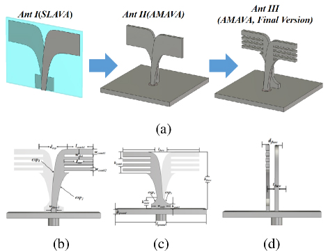
Figure 1: Diagram of the proposed antenna: (a) evolution process of the SLAVA to the enhanced AMAVA, (b) flare fed by the coaxial probe, (c) flare connected with the ground, and (d) side view (l 9.5 mm, w 2 mm, w 0.93 mm, l 11 mm, w 1.1 mm, w 1.9 mm, d 11.6 mm, l 35 mm, h 2 mm, h 5.2 mm, h 2 mm, w 7.6 mm, l 30.2 mm, h 24 mm, h 9 mm, d 1.9 mm, t 1.8 mm, r 0.6, r 0.95, r r 0.87, a 28, b 16, a 10, b 24, a 11.6, b 1.6, a 5.3, b 1.8).
B. Simulated performances at different states
Comparisons of simulated results among the three antennas are shown in Figs. 2 (a-b). According to the PHC calculating method:
| (1) |
Input power P is 0.5 W, breakdown E-field intensity E in the air is 3 MV/m and E is the maximum E-field intensity. It is obvious that lowering the value of E is helpful to increase PHC. The simulated PHC values of Ant I are no more than 1000 W and cannot satisfy the basic demand of the HPM system. For the purpose of enhancing the PHC of the AVA, Ant II is a version of the all-metallic Ant I, whose simulated PHC values are improved significantly and over 8000 W in the operating band. However, the operating bandwidth and resonance depth of Ant II are narrow and shallow due to the all-metal structure. The deepest resonance depth is 15.5 dB at 9.8 GHz, and the 10 dB impedance bandwidth of Ant II covers 8.25-11.1 GHz. The shallow resonance depth of Ant II has the potential to influence the electric components, such as the low-noise amplifier. Considering this issue, with slots on the brims of the Vivaldi flares, some bandwidths are sacrificed to ensure enough resonance depth. The simulated 10 dB impedance bandwidth of Ant III can cover 8.62-10.66 GHz, and its deepest resonance depth can reach 29.5 dB at 9.8 GHz. Introducing slots, the E-field distributions of the AMAVA are changed, and its maximum E-field intensity is reduced, resulting in some improvements in simulated PHC at target frequencies according to equation (1).
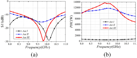
Figure 2: Comparison among simulated results of Ant I, Ant II and Ant III (a) S11 and (b) PHC.
Comparisons of the simulated radiation patterns of the three antennas are listed in Figs. 3 (a-b). E-plane and H-plane radiation patterns of Ant I show great symmetry and are close to the shapes of ‘8’ and ‘0’, respectively. The antenna will be arranged in an array for the HPM radiation, and the back lobe of Ant I is too noticeable and will lead to strong back radiation, which has the potential to destroy irrelevant electrical components in the back end, so that it cannot apply in the HPM application. For some antenna arrays, they are examined for a certain angular deflection, so that the main lobe of the element antenna does not travel along the axis. When the original antenna undergoes metallization and transits to Ant II and Ant III, the radiation direction of E-plane patterns will deviate 7-8 from the main axis, and an asymmetry shows in E-plane and H-plane radiation patterns in the operating band. Thanks to the loading of the ground plane in Ant II and Ant III designs, their back radiation lobes are nearly eliminated and facilitation of antenna fixing is obtained.
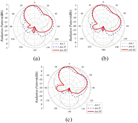
Figure 3: Simulated E-plane radiation patterns of Ant I, Ant II and Ant III at (a) 9.3 GHz, (b) 9.8 GHz, and (c) 10.3 GHz.
C. Parameter study
A detailed optimum process of AMAVA will be presented in this section. First, an analysis of antenna performance will be given from the aspect of the structure of AMAVA itself. The thickness of the flare as well as the width of the flare is considered a significant parameter to influence impedance match and PHC. On the one hand, the size of the coaxial probe and the dielectric material restricts the thickness of the flare, so that the thickness of the flare and the width of the flare should be between them (1.27-4.1 mm). Once out of this range, the bottom of the flare will be punctured or a short circuit will occur. On the other hand, satisfying simulated results are obtained when t, as depicted inFigs. 4 (a-b).
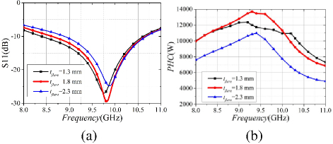
Figure 4: Simulated results corresponding to different flare thickness values t (a) S11 and (b) PHC.
As shown in Figs. 5 (a-b), the width of the AMAVA flare connected to the ground plane affects impedance match and PHC. When w increases from 1.4 mm to 2.4 mm, the resonance point will deviate and deepen, while PHC values in the operating band emerge with an opposite tendency. Therefore, the middle value of 1.9 mm is considered the optimum parameter for w.
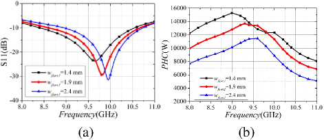
Figure 5: Simulated results corresponding to different width values of the flare w (a) S11 and (b) PHC.
Meanwhile, it is exerting a great influence on the S11 and PHC of the AMAVA presented in Figs. 6 (a-b) for the distance between two flares. The simulated S11 deviates left and shallows with d increases. When d and 2.4 mm, PHC values remain relatively stable. PHC values go down rapidly in the main operating band when d goes to 1.4 mm.
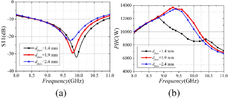
Figure 6: Simulated results corresponding to different distance values between the two flares d (a) S11 and (b) PHC.
To further enhance the ability of AMAVA, a rectangular tuning stub with exponential corner cuts is loaded on the bottom of the flare, which connects with the ground plane. In Figs. 7 (a-b), simulated resonance goes deeper when h increases. As for PHC value, it reaches its peak when h.
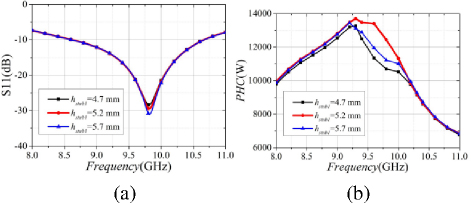
Figure 7: Simulated results corresponding to different height of stub values h (a) return loss and (b) PHC.
Rectangular slots are employed on the flare of the AMAVA, and its influence on the antenna performance is depicted in Figs. 8 (a-b). With l and w increasing, the resonance depth and magnitude of the PHC are greatly improved due to the comb-like flare structure.
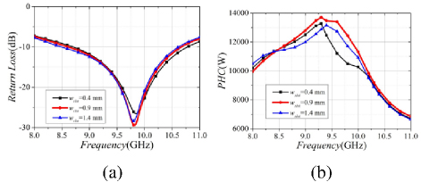
Figure 8: Simulated return loss results corresponding to different value lengths of the slot l.
III. FABRICATION AND VERIFICATION
The prototype of the proposed antenna, which consists of two Vivaldi comb-like flares, an SMA ensuring HPM and a rectangular ground plate, is shown in Figs. 9 (a-b). Aluminum is selected as the metallic material for its light weight, low cost and durability in the HPM application. An SMA connector SMA-KFD3-1, manufactured by Gwave Technology Co. Ltd., which has an eligible PHC, is employed in the fabrication of AMAVA. The feed probe punctures through the ground plate and connects to the bottom of the Vivaldi comb-like flare. The outer dielectric material of the SMA inserts into the ground plate, on whose back the flange fixes the whole antenna design.
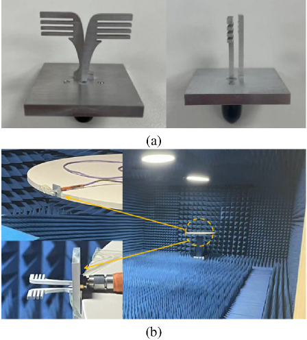
Figure 9: Prototype of AMAVA (a) front view and side view and (b) in the anechoic chamber.
In Fig. 10, the measured and simulated S11 results are depicted and show a satisfying agreement. The measured S11 of the AMAVA covers 8.3-10.66 GHz, which is wider at low frequencies than that in the simulation, and its deepest resonance over frequency reaches 29.7 dB at 9.75 GHz.
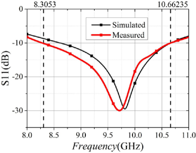
Figure 10: Measured and simulated S11 results of AMAVA.
The measured and simulated radiation patterns at three frequency points of the AMAVA are presented in Fig. 11. For E-plane radiation patterns, the measured values and their variation tendency are in good agreement with the simulation. The deviations of maximum radiation direction are between 7 and 8, and the peak realized gain values are 4.54 dBi, 5.68 dBi and 5.71 dBi at 9.3 GHz, 9.8 GHz and 10.3 GHz, respectively. Levels of the measured back lobes are 2 dBi higher than the simulated results. As for the H-plane, the symmetry of measured radiation patterns keeps stable, while measured beamwidths are narrower than simulation beamwidths at selected frequencies.
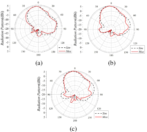
Figure 11: Measured and simulated E-plane radiation patterns of AMAVA at (a) 9.3 GHz, (b) 9.8 GHz and (c) 10.3 GHz.
To verify the PHC of the proposed antenna, an HPM experiment involving two of the same AMAVAs (No. 1 and No. 2) measured at 9 GHz will be conducted as shown in Fig. 12. One proposed antenna is fed by an HPM source of 8000 W as a transmitting antenna, and the other one, as a receiving antenna, is connected through a 20 dB attenuator to a signal analyzer, which monitors and records the operating status of the HPM system. To test whether AMAVA can bear the PHC of 8000 W-level, the curve on the signal analyzer should be observed while the HPM source is on. If the curve remains stable for 10 minutes, AMAVA is deemed qualified with the PHC of 8000 W level. If the curve changes greatly, the proposed antenna cannot be applied in the HPM system. Figure 13 and Table 1 depict the measured result on the signal analyzer at 9 GHz. The measured peak values of the AMAVA design on the signal analyzer are 2.31 dBm and 2.32 dBm, respectively. Exchanging the transmitting and the receiving antenna, the measured peak values in the second experiment are 2.28 dBm and remain unchanged. The measured results demonstrate the proposed antenna is qualified with 8000 W-level PHC, which shows its ability in the HPM system.
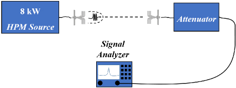
Figure 12: Diagram of the PHC experiment.
Table 1: Measured peak values of AMAVA
| 0 min | 10 min | |
| No.1 | 2.31 dBm | 2.32 dBm |
| No.2 | 2.28 dBm | 2.28 dBm |
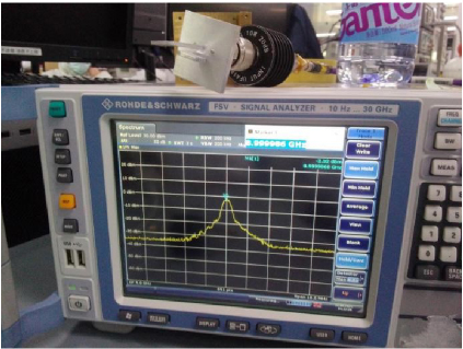
Figure 13: Measured results on the signal analyzer at 9 GHz.
Table 2: Comparison of the AMAVA with public VAs
| Ref | Type | Size | Bandwidth | Application |
| This work | AMAVA | 0.870.69 | 8.3-10.7 GHz | HPM |
| [14] | Sub-AVA | 0.870.4 | 1-28 GHz | UWB |
| [15] | Sub-AVA | 20.8 | 6-12 GHz | Moisture Sensor |
| [16] | Sub-AVA | 0.130.08 | 0.6-3 GHz | Microwave Imaging System |
| [17] | Sub-AVA | 0.750.75 | 1.5-3.3 GHz | Microwave Imaging System |
| [18] | AMVA | 0.530.4 | 2-50 GHz | UWB |
| [19] | AMVA | 0.320.3 | 2-6 GHz | Wireless Comm |
| [20] | AMVA | 30.7 | 6-12 GHz | Phased Array |
| [21] [22] |
AMVA | 2.40.6 | 2-6 GHz | HPM |
| [23] | AMVA | 0.610.33 | 8-12 GHz | Radar |
| [24] | AMVA | 0.690.09 | 2-18 GHz | Radar |
| [25] | AMVA | 0.40.06 | 2.6-21.2 GHz | UWB |
For a better understanding of the AMAVA design, a comparison with public VA designs is listed in Table 2, showing their characteristics in terms of antenna type, dimension, operating band and application. VA designs in [14–17] are AVA on the substrate with wideband characteristic. However, the PHC values of the VA designs loaded on the PCB are unqualified for the HPM systems. With a measured PHC of more than 8000 W, the proposed antenna design in this letter is appropriate for use in the HPM systems. References [18–25] are metallizing VA designs, among which that in [22] is applied for the HPM systems, and its simulated maximum E-field intensity is mentioned. According to equation (1), the PHC value of the VA design in [22] is 471 kW at 4 GHz. In general, the larger the microwave component, the lower the maximum E-field intensity (the higher the PHC). The size of a microwave component is in direct proportion to its lowest operating frequency. Therefore, working at lower frequencies and having a larger size, the proposed VA design in [22] is made to have a higher PHC compared to the AMAVA proposed in this paper.
IV. CONCLUSION
To solve the inability of the sub-loaded AVA for the HPM application, an all-metal antipodal antenna is proposed, designed and verified in this paper. Making the radiation flare all metallic, the PHC of the AMAVA is much improved. Rectangular tuning stub and slot are loaded on the antenna design, whose resonance depth and maximum PHC value are further enhanced. The prototype of the proposed antenna is fabricated and verified in the anechoic chamber, and its measured results are in good agreement with simulations. An 8000 W-level PHC experiment is conducted at 9 GHz, certifying the potential of AMAVA in the HPM systems. Consistent efforts will be made in terms of antenna miniaturization, cross-polarization optimization and bandwidth expansion in the future.
ACKNOWLEDGMENT
This work is supported by the Hunan science and technology project (outstanding science and technology innovative youth) under Grant 2023RC3266.
REFERENCES
[1] A. Bhattacharjee, A. Bhawal, A. Karmakar, and A. Saha, “Vivaldi antennas: A historical review and current state of art,” International Journal of Microwave and Wireless Technologies, vol. 13, pp. 833-850, 2021.
[2] B. Wu, X.-Y. Sun, H.-R. Zu, and H.-H. Zhang, “Transparent ultrawideband halved coplanar Vivaldi antenna with metal mesh film,” IEEE Antennas Wireless Propag. Lett., vol. 21, no. 12, pp. 2532-2536, 2022.
[3] S. Ramesh and T. Rama Rao, “High gain dielectric loaded exponentially tapered slot antenna based on substrate integrate waveguide for V-band wireless communications,” Applied Computation Electromagnetics Society (ACES) Journal, vol. 29, no. 11, pp. 870-880, Nov. 2014.
[4] H. Lv, Q. Huang, J. Hou, and J. Liu, “Wideband dual-polarized Vivaldi antenna with gain enhancement,” Applied Computation Electromagnetics Society (ACES) Journal, vol. 33, no. 9, pp. 990-996, Sep. 2018.
[5] H. Zhu, X. Li, L. Yao, and J. Xiao, “A novel dielectric loaded Vivaldi antenna with improved radiation characteristics for UWB application,” Applied Computation Electromagnetics Society (ACES) Journal, vol. 33, no. 4, pp. 394-399, Apr. 2018.
[6] S. Pan, W. Shen, Y. Feng, and Z. Liu, “Miniaturization and performance enhancement of Vivaldi antenna based on ultra-wideband metasurface lens,” Int. J. Electron. Commun., vol. 134, pp. 1-7, 2021.
[7] A. Hossain and A.-V. Pham, “A novel gain-enhanced miniaturized and lightweight Vivaldi antenna,” IEEE Trans. Antennas Propag., vol. 71, no. 12, pp. 9431-9439, 2023.
[8] H. Qi and H. Liu, “Single-ended band-notched Vivaldi antenna with common mode suppression and low cross polarization,” IEEE Antennas Wireless Propag. Lett., vol. 20, no. 10, pp. 1983-1987, 2021.
[9] K. Zhang, R. Tan, Z. H. Jiang, Y. Huang, and L. Tang, “A compact, ultrawideband dual-polarized Vivaldi antenna with radar cross section reduction,” IEEE Antennas Wireless Propag. Lett., vol. 21, no. 7, pp. 1323-1327, 2022.
[10] X. Liu, Y. Zhu, and W. Xie, “A miniaturized wideband directional circularly polarized antenna based on bent Vivaldi antenna structure,” IEEE Antennas Wireless Propag. Lett., vol. 22, no. 2, pp. 298-302, 2023.
[11] J. Liang, C. Chiu, T. Lin, and C. Lee, “An ultrawideband circularly-polarized Vivaldi antenna with high gain,” IEEE Access, vol. 10, pp. 100446-100455, 2022.
[12] T. Zhang, Y. Chen, Z. Liu, and S. Yang, “A low-scattering Vivaldi antenna array with slits on nonradiating edges,” IEEE Trans. Antennas Propag., vol. 71, no. 2, pp. 1999-2004, 2023.
[13] F. Gunes, I. O. Evranos, M. A. Belen, and P. Mahouti, “A compact triband antipodal Vivaldi antenna with frequency selective surface inspired director for IoT/WLAN applications,” Wireless Networks, vol. 27, pp. 3195-3205, 2021.
[14] X. Shi, Y. Cao, Y. Hu, and X. Luo, “A high-gain antipodal Vivaldi antenna with director and metamaterial at 1-28 GHz,” IEEE Antennas Wireless Propag. Lett., vol. 20, no. 12, pp. 2432-2436,2021.
[15] F. Stern, W. Taute, R. Knöchel, and M. Höft, “Dual antipodal Vivaldi antenna-based moisture sensor for industrial process control,” IEEE Sensors Journal, vol. 23, no. 19, pp. 22430-22439, 2023.
[16] M. Wang, L. Crocco, S. Costanzo, and R. Scapaticci, “A compact slot-loaded antipodal Vivaldi antenna for a microwave imaging system to monitor liver microwave thermal ablation,” IEEE Open Journal of Antennas and Propagation, vol. 3, pp. 700-708, 2022.
[17] A. M. de Oliveira, A. M. de Oliveira Neto, M. B. Perotoni, and N. Nurhayati, “A fern antipodal Vivaldi antenna for near-field microwave imaging medical applications,” IEEE Trans. Antennas Propag., vol. 69, no. 12, pp. 8816-8829, 2021.
[18] C. Zhao, Y. Bai, and Q. Wei, “A 2 to 50 GHz all-metal Vivaldi antenna for ultra-wideband (UWB) application,” Int. J. Electron. Commun., vol. 148, pp. 1-6, 2022.
[19] Y. Chuo, L. Ziting, L. Qiang, and D. Haosheng, “Design of a metal Vivaldi antenna with wide band and dual polarization,” in 2021 IEEE International Workshop on Electromagnetics: Applications and Student Innovation Competition (iWEM), Guangzhou, China, pp. 1-3, 2021.
[20] X. Ma, S. Chai, K. Xiao, and L. Ding, “Design of all-metal Vivaldi phased array antenna,” in 2018 IEEE 3rd International Conference on Signal and Image Processing (ICSIP), Shenzhen, China, pp. 547-551, 2018.
[21] T. H. Lim, S. Park, C. S. Lee, and J.-R. Park, “A broadband dual-slant polarized metal Vivaldi antenna for a high-power jammer,” in 2020 International Symposium in Antennas and Propagation (ISAP), Osaka, Japan, pp. 485-486, 2021.
[22] S. Ohm, E. Kang, T. H. Lim, and H. Choo, “Design of a dual-polarization all-metal Vivaldi array antenna using a metal 3D printing method for high-power jamming systems,” IEEE Access, vol. 11, pp. 35175-35181, 2023.
[23] R. W. Kindt and W. R. Pickles, “Ultrawideband all-metal flared-notch array radiator,” IEEE Trans Antennas Propag., vol. 58, no. 11, pp. 3568-3575, 2010.
[24] J.-B. Yan, S. Gogineni, B. Camps-Raga, and J. A. Brozena, “A dual-polarized 2-18-GHz Vivaldi array for airborne radar measurements of snow,” IEEE Trans Antennas Propag., vol. 64, no. 2, pp. 781-785, 2016.
[25] R. W. Kindt and R. Pickles, “12-to-1 bandwidth all-metal Vivaldi array element,” in IEEE Antennas Propagation Symp., pp. 1-4, 1-5 June 2009.
BIOGRAPHIES

Zichong Chen received the M.E. degree from Hunan University in 2023. He works full-time as a microwave engineer for Hunan Vanguard Group Co. Ltd. His research interests include HPM antenna, flexible antenna and UWB antenna design.

Rui Yin received the M.E. degree from Nanjing University of Science and Technology in 2018. She works full-time as a microwave engineer at Hunan Vanguard Group Co. Ltd. Her current research interests include HPM antenna and high-performance microwave circuits.

Yun Jiang received the Ph.D. degree from National University of Defense Technology in 2022. He works full-time as a senior microwave engineer at Hunan Vanguard Group Co. Ltd. His current research interests include HPM overall system design, microwave RF circuit and radar technology.

Xiaojun Mao received the Ph.D. degree from Harbin Engineering University in 2017. He works full-time as a senior microwave engineer at Hunan Vanguard Group Co. Ltd. His current research interests include the HPM overall system design, antenna array algorithm and radar technology.

Pengjie Lv received the M.E. degree from Shenyang University of Science and Technology in 2009. He works full-time as a microwave engineer at Hunan Vanguard Group Co. Ltd. His current research interests include HPM overall system design.

Shangyi Jiang received the M.E. degree from Nanjing University of Science and Technology in 2023. He works full-time as a microwave engineer at Hunan Vanguard Group Co. Ltd. His current research interests include HPM source design and electromagnetic compatibility.

Yang Liu received the B.E degree from Changsha University of Science and Technology in 2020. He works full-time as a microwave engineer at Hunan Vanguard Group Co. Ltd. His current research interests include HPM antenna and damage effect.
ACES JOURNAL, Vol. 39, No. 12, 1066–1072
doi: 10.13052/2024.ACES.J.391205
© 2024 River Publishers