A Dual-input Electromagnetic Inverse Scattering Algorithm Based on Improved U-net
Chun Xia Yang, Jun Jie Meng, Shuang Wei, and Mei Song Tong
1Shanghai Engineering Research Center of Intelligent Education and Bigdata
Shanghai Normal University, Shanghai 200234, China
chunxiay@shnu.edu.cn, 1000467188@smail.shnu.edu.cn, weishuang@shnu.edu.cn
2Department of Electronic Science and Technology
Tongji University, Shanghai 201804, China
mstong@tongji.edu.cn
Submitted On: May 28, 2024; Accepted On: October 18, 2024
ABSTRACT
In this paper, we propose a dual-input inversion method based on deep learning to improve the accuracy of electromagnetic imaging using the back propagation algorithm (BP). An improved U-Net network is utilized to reconstruct the scatterers. Unlike other deep learning inversion methods, we input both the scatterer distribution data from BP imaging and the scattered field data received by the antennas into the neural network for training. This approach leads to a more accurate prediction of scatterer positions and characteristics. Compared to predicting the scatterers using only the scattered field as input, adding the BP imaging results at the input provides the neural network with more information, significantly reduces the learning difficulty, minimizes errors, and enhances the quality of imaging. To address potential gradient vanishing and spatial information loss during network training, we integrate attention mechanisms and residual modules into the basic U-Net network. The former helps the network extract important relevant information under different contrast conditions, while the latter focuses on solving the problems of gradient vanishing and explosion. Simulation experiments confirm that our dual-input inversion method significantly reduces the average error, outperforming traditional single-input reconstruction methods.
Index Terms: back propagation (BP), dual-input inversion, improved U-Net, inverse scattering
I. INTRODUCTION
Inverse scattering theory and inversion techniques have frequently emerged and been applied to solve various scientific and engineering problems, such as remote sensing [1], medical imaging [2], and nondestructive testing [3].
Due to the nonlinearity and ill-posedness of inverse scattering problems, the common solution methods are divided into two categories: linear and nonlinear solutions. Nonlinear methods transform the nonlinear problem into an optimization problem by constructing an objective function, which is then solved iteratively with multiple times [4, 5, 6, 7, 8]. Examples include the Contrast Source Inversion (CSI) method [9] and the Distorted Born Iterative Method (DBIM) [10, 11, 12, 13]. Linear methods, on the other hand, use approximation techniques to convert the nonlinear problem into a linear one, thereby reducing complexity and increasing solving speed [14, 15]. Examples include the Born approximation [16] and the Rytov approximation [17]. Both of these approximation methods require prior information to solve the problem. The back propagation (BP) algorithm in linear solutions can be solved without iteration. Although the applicability of non-iterative inversion methods is limited, they offer high computationalefficiency [18].
With the development and widespread application of deep learning, researchers have applied deep learning to solve inverse problems. Convolutional Neural Networks (CNN) can effectively capture the implicit features of input and output data and learn the mapping relationship between them. In 2019, Wei and Chen input scattered fields into a CNN, trained the network, and then estimated the scatterers using the neural network. Their research found that this approach could effectively reconstruct the scatterers [19]. In the same year, these two researchers proposed using deep learning to solve full-wave electromagnetic scattering problems, training the network based on contrast, and discovered that it could still produce good results for tests beyond the training set [20]. Subsequently, in 2021, they used a modified contrast scheme and U-Net network to reconstruct high-contrast two-dimensional and three-dimensional objects [21]. In the same year, scholars Ahmadi and Shishegar incorporated prior information such as imaging boundaries into deep learning to solve inverse scattering problems, resulting in smoother and better imaging results [22]. In 2020, He Yang and Jun Liu successfully employed a CNN to accurately approximate the nonlinear mapping between noisy far-field patterns and the positions as well as sizes of disks suitable for unknown scatterers [23]. In 2022, Liu et al. proposed an unsupervised learning framework called CSI-GAN, which integrates the entire CSI process with an unsupervised Generative Adversarial Network (GAN). CSI provides physical constraints for the GAN, while the GAN adds topological and semantic features to the CSI, jointly achieving the inverse imaging of scatterers [24]. However, the high nonlinearity and ill-posedness reduce the generalization ability of neural networks, especially when the contrast increases, significantly affecting the imaging results. Therefore, how to incorporate more prior information, reduce the learning difficulty of neural networks, and improve generalization performance has become a major research direction for electromagnetic inversion based on deeplearning.
In this paper, we use both the scattered field and the scatterer distribution obtained by BP as inputs, with the real scatterer image as the output, allowing the neural network to learn the mapping relationship between these physical quantities. The inclusion of BP inversion results can provide more auxiliary information for the neural network, greatly reducing learning difficulty. Compared to a single-input network that uses only the BP image as input, retaining the scattered field data ensures the accuracy of the neural network output even when the quality of the BP image is poor.
The structure of this paper is as follows. The second section introduces the electromagnetic imaging problem model and the BP algorithm. The third section provides a detailed description of the improved Residual Attention U-Net (RAU) neural network structure proposed in this paper. The fourth section presents a simulation analysis, comparing the dual-input inversion method with the single-input inversion scheme to verify its efficiency. The fifth section concludes the paper.
II. INVERSE PROBLEM AND BP SCHEME
The electromagnetic imaging problem model is shown in Fig. 1. Assume an imaging region in free space, there is an unknown non-magnetic scatterer in region . The relative permittivity of the scatterer is , and the permeability is . This paper uses microwave imaging, where the transmitting and receiving antennas are located in the observation domain outside the imaging region . When the scatterer receives the incident electromagnetic wave, it generates a scattered field. The receiving antenna captures the total field, which is the superposition of the scattered field and the incident field, for subsequent imaging calculations. A detailed introduction to BP follows.
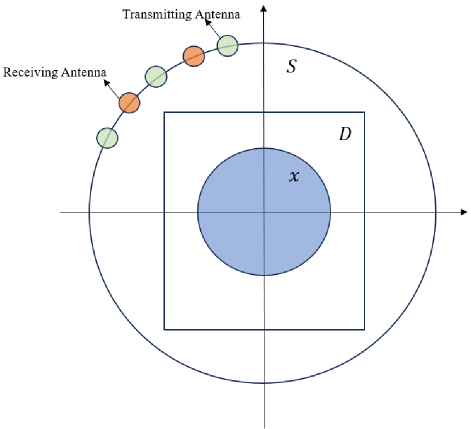
Figure 1: Electromagnetic imaging model.
The BP imaging algorithm typically consists of three steps. The first step is to determine the induced current using BP, where it is assumed that the induced current is proportional to the scattered field:
| (1) |
where is an unknown proportionality constant, is the Green’s function that represents the propagation process from the scatterer to the receiver, denotes matrix Hermitian, and is the scattered electric field. To obtain , a function between the scattered field and the calculated field is defined:
| (2) |
To minimize , the minimum value of requires that the derivative with respect to is equal to zero, thus yielding the optimal solution for :
| (3) |
where denotes the projection of and in the observation domain . Its discrete form is , where the superscripts and * denote the transpose and complex conjugate, respectively. From equation (1), it can be seen that once is determined, the induced current can be obtained.
The second step is to calculate the total field in the imaging region :
| (4) |
where denotes the incident field and is the Green’s function within the imaging domain.
The third step is to obtain the contrast by considering all incident waves, where the contrast is equal to the relative permittivity minus 1. For the -th transmitting antenna, the definition of requires that:
| (5) |
where denotes the total field received by the -th transmitting antenna. The incident field is solved using the least squares method, and is obtained and analyzed:
| (6) |
where denotes the number of incident antennas. If the scatterer is non-lossy, the contrast takes the real part of (6).
III. RECONSTRUCTION ALGORITHM BASED ON RAU
In this section, the authors primarily introduce the improved U-Net. U-Net is a common CNN, and the CNN architecture typically consists of convolutional layers, pooling layers, and fully connected layers.
U-Net was developed in 2015 by the Department of Computer Science at the University of Freiburg, Germany, for biomedical image segmentation [25]. The advantage of this network lies in its basis on a fully convolutional network, where the architecture, after modification and extension, can produce more accurate segmentation with fewer training images [25]. In some biomedical image segmentation studies [26], U-Net has shown significant performance improvement and has excellent generalization capability with a small amount of labeled data. In inverse scattering problems, the magnitude of the contrast significantly affects the imaging results. As the contrast increases, traditional imaging results theoretically become coarser [27]. The receptive field of the convolutional layers in the ordinary U-Net is limited and cannot capture the global information of coarse images, thereby failing to perceive the overall scattering situation. Therefore, it needs to beimproved.
The attention mechanism is derived from human vision research [28]. When humans process information, they selectively focus on a part of the received information and ignore other information. For example, when reading, a sentence with jumbled words does not affect reading comprehension. The attention mechanism simulates this process by assigning higher weights to important information and lower weights to irrelevant information. In neural network training, the attention mechanism helps to focus more on key information. The structure of the residual module is shown in Fig. 2. It was proposed by Kaiming He and others from Microsoft, and the residual network based on this module won the championship in the 2015 ImageNet Large Scale Visual Recognition Challenge (ILSVRC) [29]. The core idea of the residual module is to introduce shortcut connections, allowing information to be directly transmitted to subsequent layers, thereby maintaining the integrity of the information. Let be the input. After passing through the mapping function, the output is . The output of the residual module, in addition to , also adds the original input through the shortcut connection, resulting in an output of . The introduction of the residual module addresses the problem of gradient vanishing and explosion caused by the increasing number of network layers. The authors enhanced the U-Net by incorporating attention mechanisms and residual modules. This enhancement improves the global perception capability of the convolutional layers and prevents gradient vanishing and exploding problems due to the increased number of network layers. The authors named this improved network model the RAU, with the structure shown inFig. 3.
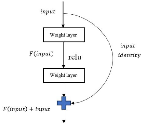
Figure 2: The structure of residual module.
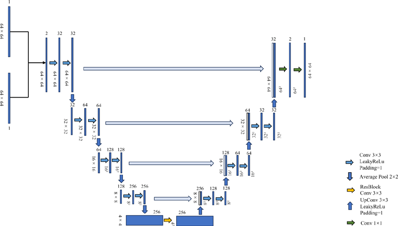
Figure 3: The structure of RAU.
In Fig. 3, the inputs are the BP image and the scattered field, and the output is the enhanced prediction from RAU. Similar to the standard U-Net, the RAU network structure is mainly divided into two parts: the left-side contracting path and the right-side expanding path. The contracting path aims to extract features from the input images, while the expanding path aims to enhance the features extracted by the contracting path. In RAU, an attention mechanism is incorporated into each convolution process, expected to enhance global perception capability. Additionally, residual modules are added during the convolution process in the fifth layer to prevent gradient explosions.
IV. NUMERICAL SIMULATION
In this section, the authors analyze the experimental results. This study uses TM electromagnetic waves, with 32 transmitting antennas and 64 receiving antennas. The frequency of the transmitting antennas is set to 400 MHz. The antennas are uniformly distributed on a circular observation domain with a radius of 3m, centered at the origin of the coordinate system. The imaging region is a square with a side length of 2 m, divided into a grid of 64×64 pixels.
In this experiment, a total of 2300 single scatterers were used, with 2000 sets used as the training dataset and 300 sets as the test dataset. The scatterers are circles of varying sizes, with radii ranging randomly between 0.1 to 0.4 m. The contrast varies randomly between 0.1 to 2.0. The centers of the circles are randomly positioned within a square formed by the vertices (-0.6 m, 0.6 m), (-0.6 m, -0.6 m), (0.6 m, -0.6 m), and (0.6 m, 0.6 m), including the boundaries. In the first set of experiments, the input is the scattered field data, while in the second set, the input consists of both the scattered field data and the BP imaging distribution data. The output for both sets of experiments is the predicted scatterer data after neural network training. The neural network is trained using the ADAM optimizer with learning rates of 0.001 and 0.0001. Training is conducted for 500 and 1000 epochs, with batch sizes of 32, 64, and 128. Since this task is a regression task, Mean Squared Error (MSE) is chosen as the loss function. The training was conducted on a GPU platform using RTX 4090 24G. After training the network, it was tested on a test set of 300 samples, and the average MSE for these 300 samples was calculated.
The test results are shown in Fig. 4. In Fig. 4 (a), the scatterer has its center at (0.2 m, -0.4 m), a radius of 0.4 m, and a contrast of 0.2. In Fig. 4 (b), the scatterer has its center at (-0.3 m, 0.1 m), a radius of 0.3 m, and a contrast of 1.5. Based on the test results, it can be observed that both single-input and dual-input imaging outperform BP imaging results. Furthermore, dual-input imaging is superior to single-input imaging in terms of reconstructed images. To avoid chance results, the average MSE is compared further. The average MSE for the 300 test samples is shown in Table 1.
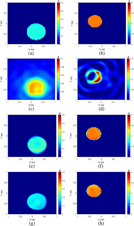
Figure 4: Comparison of BP imaging, single-input imaging and dual-input imaging for a single circle scatterer: (a) and (b) show the target scatterers, (c) and (d) show the BP imaging images, (e) and (f) show the single-input imagings, and (g) and (h) show the dual-input imagings.
Table 1: Comparison of average MSE between single-input and dual-input results
| Input | Scattered Field | |||
| Learning Rate | 0.001 | 0.0001 | ||
| Epoch/BatchSize | Average Error | Epoch/BatchSize | AverageError | |
| 500/32 | 0.008696 | 500/32 | 0.008147 | |
| 500/64 | 0.006872 | 500/64 | 0.009535 | |
| 500/128 | 0.012687 | 500/128 | 0.010621 | |
| 1000/32 | 0.008299 | 1000/32 | 0.010815 | |
| 1000/64 | 0.008472 | 1000/64 | 0.008224 | |
| 1000/128 | 0.012185 | 1000/128 | 0.009658 | |
| Input | BP Result + Scattered Field | |||
| Learning Rate | 0.001 | 0.0001 | ||
| Epoch/BatchSize | AverageError | Epoch/BatchSize | AverageError | |
| 500/32 | 0.004726 | 500/32 | 0.007976 | |
| 500/64 | 0.004683 | 500/64 | 0.007557 | |
| 500/128 | 0.005721 | 500/128 | 0.008100 | |
| 1000/32 | 0.004745 | 1000/32 | 0.008026 | |
| 1000/64 | 0.004837 | 1000/64 | 0.006845 | |
| 1000/128 | 0.005552 | 1000/128 | 0.008727 | |
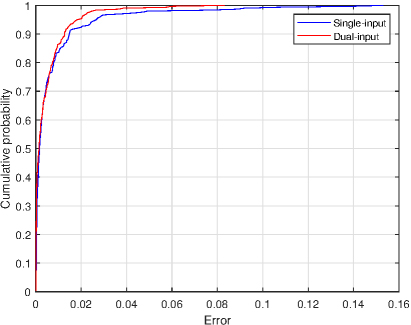
Figure 5: Probability cumulative curve for the single-circle tests.
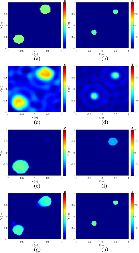
Figure 6: Test results of generalization ability of the algorithm for two circular scatterers: (a) and (b) show the target scatterers, (c) and (d) show the BP imaging images, (e) and (f) show the single-input imagings, and (g) and (h) show the dual-input imagings.
As shown in Table 1, the red text highlights the minimum errors achieved under both the single-input and dual-input models, which correspond to the same set of parameters: a learning rate of 0.001, 500 training epochs, and a batch size of 64. Under these parameters, when the batch size increases from 32 to 64, the MSE gradually decreases; however, when the batch size increases from 64 to 128, the MSE gradually increases. The red texts represent the minimum error. According to Table 1, when the learning rate is fixed at 0.001 and the training epochs are set to 500 and 1000, the error reduction for the best dual-input compared to the best single-input is 32.9% and 42.9%, respectively. When the learning rate is fixed at 0.0001 and the training epochs are set to 500 and 1000, the error reduction for the best dual-input compared to the best single-input is 20.7% and 16.8%, respectively. The single-circle test was conducted using the best parameters for both single-input and dual-input. The probability cumulative curves for the best single-input and dual-input cases are shown in Fig. 5, where it can be seen that the overall test error for single-input is greater than that for dual-input, with MSE of 0.006872 and 0.004683, respectively. The dual-input method shows a 31.9% reduction in MSE compared to the single-input method, demonstrating a significant advantage.
To test the generalization ability of the RAU network, 50 sets of double circles were used as the test set to evaluate the network’s performance. The average computational time per sample was 0.212 seconds. The test results are shown in Fig 6. In Fig. 6 (a), the centers of the two circles are located at (-0.6 m, -0.6 m) and (0.4 m, 0.7 m), both with a radius of 0.2 m and a contrast of 1.0. In Fig. 6 (b), the centers are located at (-0.3 m, -0.3 m) and (0.5 m, 0.6 m), both with a radius of 0.1 m and a contrast of 0.9. According to the test results, in the case of double circles, the dual-input scheme is significantly better than the single-input scheme. The single-input scheme can only reconstruct one circle, and the reconstruction effect becomes worse when the contrast is high. In contrast, the dual-input scheme can still reconstruct two circular scatterers well, regardless of whether the contrast is low or high. The probability cumulative curves for the 50 tests are shown in Fig. 7. Compared to the single-circle tests, the dual-circle tests clearly show that, under the same conditions, the dual-input has a significantly smaller error than the single-input, as illustrated by the error curve. The average MSEs for single-input and dual-input are 0.066458 and 0.037245, respectively. The dual-input error is reduced by 44% compared to the single-input error. From the comparison of single circle and double circle imaging between single-input and dual-input, it can be concluded that dual-input has better reconstruction performance than single-input.
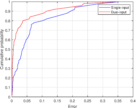
Figure 7: Probability cumulative curve for the double-circle tests.
Subsequently, the algorithm’s generalization ability was further evaluated using measurement data provided by the Fresnel Institute. It should be noted that the measurement model [30] slightly deviates from our adopted simulation imaging model. For this evaluation, we specifically selected the ”dielTM dec8f.exp” dataset with an excitation wave frequency of 4GHz. The reconstructed target in this case is a circular scatterer positioned 30 mm away from the origin, having a radius of 15 mm and a relative permittivity value within the range of 3±0.3. The imaging result depicted in Fig. 8 demonstrates that, despite significant variations in antenna position, excitation frequency, and scatterer size, the target can still be accurately reconstructed using RAU.
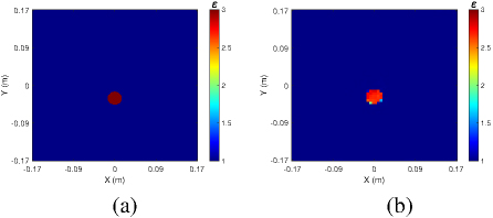
Figure 8: Experimental results reconstructed by the dataset at 4 GHz: (a) the ground truth image and (b) the output image of RAU.
V. CONCLUSION
This paper proposes a dual-input electromagnetic inverse scattering imaging method based on RAU. Unlike traditional single-input deep learning inversion methods, which only input the scattered field, this method additionally inputs the scatterer distribution obtained by BP imaging along with the scattered field. Consequently, the neural network can receive more effective information. Compared to U-Net, RAU enhances the global perception ability of the convolutional layers through its attention mechanism, and its residual modules address the problem of gradient explosion that can occur with deeper network structures. This dual-input scheme results in smaller imaging errors. The authors validated the above by conducting single-circle and double-circle tests, demonstrating the effectiveness of the method. Further improvements in imaging performance will be considered in future research.
ACKNOWLEDGMENT
This work was supported by the National Natural Science Foundation of China under the Project No. 62071331.
REFERENCES
[1] L. Xie, J. Huo, Y. Huang, C. Guo, and Q. Zhao, “Non-iterative methods based on dictionary learning for inverse scattering problems,” in IGARSS 2022 - 2022 IEEE International Geoscience and Remote Sensing Symposium, Kuala Lumpur, Malaysia, pp. 2123-2126, 2022.
[2] R. Scapaticci, P. Kosmas, and L. Crocco, “Wavelet-based regularization for robust microwave imaging in medical applications,” IEEE Transactions on Biomedical Engineering, vol. 62, no. 4, pp. 1195-1202, 2014.
[3] O. Mudanyali, S. Yildiz, O. Semerci, A. Yapar, and I. Akduman, “A microwave tomographic approach for nondestructive testing of dielectric coated metallic surfaces,” IEEE Geoscience and Remote Sensing Letters, vol. 5, no. 2, pp. 180-184, 2008.
[4] C. Yang, J. Zhang, and M. S. Tong, “An FFT-accelerated particle swarm optimization method for solving far-field inverse scattering problems,” IEEE Transactions on Antennas and Propagation, vol. 69, no. 2, pp. 1078-1093, 2020.
[5] M. S. Tong, K. Yang, W. T. Sheng, and Z. Y. Zhu, “Efficient reconstruction of dielectric objects based on integral equation approach with Gauss-Newton minimization,” IEEE Transactions on Image Processing, vol. 22, no. 12, pp. 4930-4937, Dec. 2013.
[6] M. S. Tong and C. X. Yang, “A meshless method of solving inverse scattering problems for imaging dielectric objects,” IEEE Transactions on Geoscience and Remote Sensing, vol. 54, no. 2, pp. 990-999, Feb. 2016.
[7] L. E. Sun and M. S. Tong, “Reconstruction of 3D anisotropic objects by VIE and model-based inversion methods,” Progress in Electromagnetics Research C, vol. 83, pp. 97-111, 2018.
[8] C. X. Yang, J. Zhang, and M. S. Tong, “A hybrid inversion method based on the bat algorithm for microwave imaging of two-dimensional dielectric scatterers,” Progress in Electromagnetics Research M, vol. 102, pp. 91-104, Jan. 2021.
[9] P. M. Van den Berg and A. Abubakar, “Contrast source inversion method: State of art,” Progress in Electromagnetics research, vol. 34, no. 11, pp. 189-218, 2001.
[10] W. C. Chew and Y.-M. Wang, “Reconstruction of two-dimensional permittivity distribution using the distorted Born iterative method,” IEEE Transactions on Medical Imaging, vol. 9, no. 2, pp. 218-225, 1990.
[11] C. X. Yang and M. S. Tong, “A novel diffraction tomographic algorithm for remote reconstruction with limited observation angles,” International Journal of Numerical Modelling: Electronic Networks, Devices and Fields, vol. 32, no. 5, pp. 1-10, 2019.
[12] Y. He, L. Zhang, and Mei Song Tong, “Microwave imaging of 3D dielectric-magnetic penetrable objects based on integral equation method,” IEEE Transactions on Antennas and Propagation, vol. 71, no. 6, pp. 5110-5120, June 2023.
[13] B. Q. Wang, D. T. Zhang, and M. S. Tong, “Microwave imaging for highly-anisotropic objects based on Gauss-Newton minimization method,” in 2023 Progress in Electromagnetics Research Symposium, Prague, Czech, July 2023.
[14] C. X. Yang, J. Zhang, and M. S. Tong, “A hybrid quantum-behaved particle swarm optimization algorithm for solving inverse scattering problems,” IEEE Transactions on Antennas and Propagation, vol. 69, no. 9, pp. 5861-5869, 2021.
[15] M. S. Tong and W. C. Chew, “Multilevel fast multipole acceleration in the Nyström discretization of surface electromagnetic integral equations for electromagnetic scattering by composite objects,” IEEE Transactions on Antennas and Propagation, vol. 58, no. 10, pp. 3411-3416, Oct.2010.
[16] A. Onufriev, D. A. Case, and D. Bashford, “Effective Born radii in the generalized Born approximation: The importance of being perfect,” Journal of Computational Chemistry, vol. 23, no. 14, pp. 1297-1304, 2002.
[17] A. Devaney, “Inverse-scattering theory within the Rytov approximation,” Optics Letters, vol. 6, no. 8, pp. 374-376, 1981.
[18] X. Chen, Computational Methods for Electromagnetic Inverse Scattering. Hoboken, NJ, USA: Wiley, 2018.
[19] Z. Wei and X. Chen, “Solving full-wave nonlinear inverse scattering problems by deep learning schemes,” in 2019 IEEE International Conference on Computational Electromagnetics (ICCEM), pp. 1-2, IEEE, 2019.
[20] X. Chen and Z. Wei, “Generalization capabilities of deep learning schemes in solving inverse scattering problems,” in 2019 IEEE International Symposium on Antennas and Propagation and USNC-URSI Radio Science Meeting, pp. 215-216, IEEE, 2019.
[21] Y. Zhou, Y. Zhong, Z. Wei, T. Yin, and X. Chen, “An improved deep learning scheme for solving 2-D and 3-D inverse scattering problems,” IEEE Transactions on Antennas and Propagation, vol. 69, no. 5, pp. 2853-2863, 2020.
[22] L. Ahmadi and A. A. Shishegar, “Embedding a priori information in inverse scattering problems using deep learning,” in 2021 IEEE International Symposium on Antennas and Propagation and USNC-URSI Radio Science Meeting (APS/URSI), pp. 2006-2007, IEEE, 2021.
[23] H. Yang and J. Liu, “A qualitative deep learning method for inverse scattering problems,” Applied Computational Electromagnetics Society (ACES) Journal, pp. 153-160, 2020.
[24] C. Liu, L. Li, and T. Cui, “Physics-informed unsupervised deep learning framework for solving full-wave inverse scattering problems,” in 2022 IEEE Conference on Antenna Measurements and Applications (CAMA), pp. 1-4, IEEE,2022.
[25] O. Ronneberger, P. Fischer, and T. Brox, “U-net: Convolutional networks for biomedical image segmentation,” in Medical Image Computing and Computer-Assisted Intervention–MICCAI 2015: 18th International Conference, Munich, Germany, October 5-9, 2015, Proceedings, part III 18, pp. 234-241, Springer, 2015.
[26] Z. Ahmed, S. A. Tanim, F. S. Prity, H. Rahman, and T. B. M. Maisha, “Improving biomedical image segmentation: An extensive analysis of U-Net for enhanced performance,” in 2024 Second International Conference on Emerging Trends in Information Technology and Engineering (ICETITE), pp. 1-6, IEEE, 2024.
[27] M. I. Hosen and M. B. Islam, “Masked face inpainting through residual attention UNet,” in 2022 Innovations in Intelligent Systems and Applications Conference (ASYU), pp. 1-5, IEEE,2022.
[28] M.-H. Guo, T.-X. Xu, J.-J. Liu, Z.-N. Liu, P.-T. Jiang, T.-J. Mu, S.-H. Zhang, R. R. Martin, M.-M. Cheng, and S.-M. Hu, “Attention mechanisms in computer vision: A survey,” Computational Visual Media, vol. 8, no. 3, pp. 331-368, 2022.
[29] K. He, X. Zhang, S. Ren, and J. Sun, “Deep residual learning for image recognition,” in Proceedings of the IEEE Conference on Computer Vision and Pattern Recognition, pp. 770-778, 2016.
[30] K. Belkebir and M. Saillard, “Testing inversion algorithms against experimental data,” Inverse Problems, vol. 17, no. 6, p. 1565, 2001.
BIOGRAPHIES

Chun Xia Yang received the Ph.D. degree in electronic science and technology from Tongji University, Shanghai, China, in 2017. During her doctoral studies, she also conducted research at the Department of Electrical and Computer Engineering, University of Illinois at Urbana-Champaign, Champaign, IL, USA as a visiting student between 2014 and 2016. She is currently an associate professor at the Department of Communication Engineering, Shanghai Normal University, Shanghai, China. Her ongoing research interests primarily revolve around electromagnetic inverse scattering for imaging and computational electromagnetics.
Jun Jie Meng received the B.S. degree in Communication Engineering from Shanghai Normal University, China, in 2022 and is currently pursuing his M.S. degree at the same institution. His research primarily focuses on the field of electromagnetic inverse scattering.

Shuang Wei received the B.S. degree and the M.S. degree from the Huazhong University of Science and Technology, Wuhan, China, in 2005 and 2007 respectively, and the Ph.D. degree in electrical and computer engineering from the University of Calgary, Calgary Alberta, Canada, in 2011. She is now an Associate Professor with College of Information, Mechanical and Electrical Engineering, Shanghai Normal University, Shanghai, China. From 2021 to 2022, she was a Visiting Scholar at the Shanghai Key Laboratory of Navigation and Location-based Services, School of Sensing Science and Engineering, School of Electronic Information and Electrical Engineering, Shanghai Jiao Tong University, Shanghai, China. Her current research interests include array signal processing, signal estimation and detection, computational intelligence, and compressed sensing.
Meisong Tong received the B.S. and M.S. Degrees from Huazhong University of Science and Technology, Wuhan, China, respectively, and Ph.D. degree from Arizona State University, Tempe, Arizona, USA, all in electrical engineering. He is currently the Humboldt Professor at the Technical University of Munich, Munich, Germany; the Distinguished/Permanent Professor, Head of Department of Electronic Science and Technology, and Vice Dean of College of Microelectronics, Tongji University, Shanghai, China. He has also held an adjunct professorship at the University of Illinois at Urbana-Champaign, Urbana, Illinois, USA, and an honorary professorship at the University of Hong Kong, China. He has published more than 700 papers in refereed journals and conference proceedings and co-authored six books or book chapters. His research interests include electromagnetic field theory, antenna theory and design, simulation and design of RF/microwave circuits and devices, interconnect and packaging analysis, inverse electromagnetic scattering for imaging, and computational electromagnetics.
Prof. Tong is a Fellow of the Electromagnetics Academy, Fellow of the Japan Society for the Promotion of Science (JSPS), and Senior Member (Commission B) of the USNC/URSI. He has been the chair of Shanghai Chapter since 2014 and the chair of SIGHT committee in 2018, respectively, in IEEE Antennas and Propagation Society. He has served as an associate editor or guest editor for several well-known international journals, including IEEE Antennas and Propagation Magazine, IEEE Transactions on Antennas and Propagation, IEEE Transactions on Components, Packaging and Manufacturing Technology, International Journal of Numerical Modeling: Electronic Networks, Devices and Fields, Progress in Electromagnetics Research, and Journal of Electromagnetic Waves and Applications, etc. He also frequently served as a session organizer/chair, technical program committee member/chair, and general chair for some prestigious international conferences. He was the recipient of a Visiting Professorship Award from Kyoto University, Japan, in 2012, and from University of Hong Kong, China, 2013. He advised and coauthored 15 papers that received the Best Student Paper Award from different international conferences. He was the recipient of the Travel Fellowship Award of USNC/URSI for the 31th General Assembly and Scientific Symposium (GASS) in 2014, Advance Award of Science and Technology of Shanghai Municipal Government in 2015, Fellowship Award of JSPS in 2016, Innovation Award of Universities’ Achievements of Ministry of Education of China in 2017, Innovation Achievement Award of Industry-Academia-Research Collaboration of China in 2019, “Jinqiao” Award of Technology Market Association of China in 2020, Baosteel Education Award of China in 2021, Carl Friedrich von Siemens Research Award of the Alexander von Humboldt Foundation of Germany in 2023, and Technical Achievement Award of Applied Computational Electromagnetic Society (ACES) of USA in 2024. In 2018, he was selected as the Distinguished Lecturer (DL) of IEEE Antennas and Propagation Society for 2019-2022.
ACES JOURNAL, Vol. 39, No. 11, 961–969
doi: 10.13052/2024.ACES.J.391104
© 2024 River Publishers