Design of a Single-fed Gain-enhanced Circularly Polarized Patch Antenna for Microwave Power Transmission
Ziyang Jiang, Zhonghua Ma, Xiaojing Sun, Weiqian Liang, and Haitao Xing
1School of Marine Information Engineering
Jimei University, Xiamen 361021, China
202121303012@jmu.edu.cn, mzhxm@jmu.edu.cn, 202321303042@jmu.edu.cn,
liangwq@jmu.edu.cn, xht2005@jmu.edu.cn,
2National Research and Development Center for Eel Processing Technology
Key Laboratory of Eel Aquaculture and Processing of Fujian Province, Fujian Provincial Engineering Research Center for Eel Processing Enterprise, Fuzhou, 350200, China,
Submitted On: August 22, 2024; Accepted On: December 19, 2024
ABSTRACT
A high-gain single-fed circularly polarized (CP) microstrip patch antenna for microwave transmission systems is proposed in this paper. Two narrow rectangular slots are added to the rectangular microstrip patch to enhance the antenna gain. The patch is rotated by 90 to form a cross microstrip patch antenna, and a pair of narrow microstrip strips are added at the edge of the cross patch along the -45 diagonal direction of the antenna to implement circular polarization. Two short rectangular microstrip lines are added on both sides of the narrow microstrips to adjust the phase of the current to further reduce the axial ratio (AR) value. The designed antenna model is simulated, fabricated and measured. The results of the measurement show that the antenna has a gain of 11.3 dB at the resonance frequency of 5.8 GHz, and the CP AR is 2.73 dB. The antenna can be applied to microwave power transmission systems and other personal wireless communication systems.
Index Terms: Axial ratio, circular polarization, gain enhancement, single-fed.
I. INTRODUCTION
With the development of science and technology, microwave power transmission (MPT) technology has attracted the attention of engineers and researchers. As the ”virtual battery” of microsystems, microwave energy transmission technology brings much convenience to work and life. A microwave energy transmission system is mainly composed of three parts: microwave transmission system, microwave transmission channel and microwave receiving system. The antenna is the key device of signal transmitting and receiving in microwave transmission system. In order to get higher power transmitting efficiency, the high gain circular polarized microstrip patch antenna is a very attractive choice.
In order to increase the distance of wireless transmission of electrical energy and the power of the transmitted electrical energy, it is necessary to transmit and receive electrical energy wirelessly with a high gain antenna. Microstrip antennas have low gain compared to horn antennas, and it is necessary to use gain enhancement techniques to improve the gain of the antenna. In addition to the traditional array design method, the gain enhancement of the antenna can also be improved by adding parasitic patches, multi-layer substrate structure and adding slots on the microstrip patch [1–4]. Cao et al. proposed to generate a new resonance mode by adding parasitic patches on the two radiating edges of the main radiating patch. The combination of the new resonant mode and the original resonant mode realizes broadband high gain performance [1]. Zhang et al. reconstructed the surface current distribution on the microstrip resonator by introducing a horizontal slot in the center of the square microstrip patch to achieve gain enhancement [2]. Hong et al. added narrow rectangular slots on the edge of the circular patch antenna to change the distribution of the reverse current, making the current distribution more consistent [3]. This operation reduced the mutual interference between the reverse current and the co-directional current in the far-field region of the antenna and enhanced the radiation of the current in the x-axis direction, thereby increasing the gain of the antenna. In [4], four short-circuit pins are placed symmetrically on the two diagonals of a square patch antenna. Due to the shunt inductance effect, these shorting pins affect the field distribution below the patch, thus improving the antenna gain.
In addition to this, there are novel designs to enhance the gain of the antenna. For example, an artificial magnetic conductor antenna with a hexagonal annular slot loaded on the ground was reported in [5]. Gain enhancement and low profile are achieved by adjusting the distance between the patch antenna and the ground at zero phase reflection frequency. Reference [6] proposes folding the ground plane at the non-radiating edge of the patch antenna to enhance the gain of the antenna without affecting the bandwidth of the original antenna. In [5–6], both realize the gain enhancement of the antenna by adding the design only on the ground plane, although there is the problem of large volume of space occupied by the antenna, which is not conducive to the integration of the antenna.
Line-polarized (LP) antennas used in MPT require strict polarization alignment of the transmitting and receiving antennas, otherwise polarization loss will be produced and the efficiency of power transmission will be reduced. Moreover, for mobile terminals, due to the random change of their position and direction, LP antennas have fatal defects for mobile terminals. In MPT systems, circularly polarized (CP) antennas can cut down the sensitivity of signal polarization, adapt to different transmission environments and demands, reduce the power loss caused by polarization mismatch, and thus improve the efficiency of power transmission. However, it is challenging to make the antenna with both circular polarization and high gain performance. References [7–8] utilized a two-layer antenna structure to realize the CP design of antennas, but their gains are lower than 10 dB. On the basis of the CP antennas units, references [9–13] form an array to enhance the antenna gain. Although the CP and the high gain performances are implemented, a relatively complex feeding network is required.
This article proposes a gain-enhanced CP microstrip patch antenna with low profile, which can be used in microwave wireless transmission systems. By utilizing the slotting technique of the symmetric structure, the current distribution of the patch antenna can be changed to achieve gain enhancement. At the same time, by adding a pair of narrowband microstrip lines in the -45 direction of the antenna, the two rectangular patches aligned along the x-axis and y-axis can be successfully excited to produce signals of equal amplitude with a phase difference of 90, thereby achieving the characteristic of circular polarization. In addition, this antenna adopts a single dielectric layer. Compared with double-fed and microstrip-fed antennas, the single-feed antenna avoids the complex feed network of the antenna array, and it has the advantages of simple fabrication and low cost.
II. THEORY OF CIRCULAR POLARIZATION
A. Antenna directionality principle
Antennas usually radiate in a particular direction. The directivity D(,) of an antenna is defined as the ratio of the radiated power per unit steradian angle to the power received by an isotropic radiator. The directivity of an antenna can be obtained by:
| (1) |
E, H, r and P are the peak power of the electric field, the peak power of the magnetic field, the distance between the source and the test point, and the power radiated by the antenna, respectively.
The gain of an antenna is an indicator of its ability to converge power to a specific direction, which is closely related to the directionality of the antenna. The gain is not only closely related to the directionality of the antenna, but also to the radiation efficiency of the antenna. The radiation efficiency considers the potential energy loss that the antenna may experience during the radiation process. The gain of an antenna can be expressed as:
| (2) |
D(,) is the antenna directivity mentioned in equation (1), and is the radiation efficiency of the antenna, which is usually determined by the antenna design and material properties.
B. Circular polarization principle
Circular polarization of an antenna can be realized by radiating two orthogonal electric field components in the far-field region. The electric field radiated by the antenna can be expressed as:
| (3) |
Here, and denote the magnitude of the electric field components in the far field of the antenna, respectively. and denote the phase shift of each field component, respectively.
Circular polarization can be achieved when the total vector of the electric field is composed of two orthogonal components with equal amplitude and a 90 phase difference between them, as expressed in the following equation:
| (4) | ||||
| (5) |
For CP waves, the electric field vector at any point in space traced as a function of time is a circle. This continuous circular motion is a unique electromagnetic property of CP waves. It ensures that the electromagnetic waves have the same radiation characteristics in all directions, thus providing a high degree of flexibility and robustness in wireless communications. The mode of polarization, on the other hand, can be determined by observing the temporal rotation of the field of the wave along the direction of propagation. If the rotation of the field is clockwise, the radiated wave is right-hand circular polarization (RHCP). If the rotation of the field is counterclockwise, the radiated wave is left-hand circular polarization (LHCP).
III. GAIN-ENHANCED CP ANTENNA DESIGN
A. Antenna structure
Figure 1 shows the structure of the designed gain-enhanced CP antenna. The antenna is implemented on F4BM substrate, with the relative dielectric constant of 2.2, the loss tangent angle tan of 0.001, and the thickness of the substrate is 1.5 mm. The selection of substrate materials with low dielectric constant and low loss tangent is crucial for optimizing the radiation characteristics of the antenna and reducing energy loss. Consequently, after optimizing the thickness parameter of the substrate, we have chosen F4BM with a thickness (H) of 1.5 mm as the substrate material. The antenna pattern is printed on the top layer of the dielectric plate, and the grounding plane is printed on the bottom layer, and coaxial back-feeding is used, and the feed point is set at a position F6 mm away from the center of the patch. The structure of the antenna consists of two orthogonal rectangular microstrip patches and a pair of rectangular slots placed along the x-axis and y-axis, respectively. A pair of rectangular narrow microstrip lines is added to the diagonal of the patch antenna. The detailed structure of the proposed antenna is shown in Fig. 1. The proposed antenna is simulated by a high frequency structure simulator (HFSS). Table 1 shows the final structural parameter values of the proposed antenna.
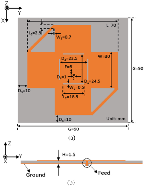
Figure 1: Proposed high gain CP patch antenna structure: (a) top view and (b) side view.
Table 1: Parameters of the proposed antenna (unit: mm)
| G | L | W | F | L | W | H |
| 90 | 70 | 30 | 6 | 18.5 | 0.5 | 1.5 |
| L | W | D | D | D | D | |
| 2.5 | 0.7 | 24.5 | 23.5 | 10 | 1 |
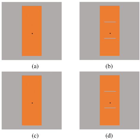
Figure 2: Evolution of the antenna structure (a) antenna I, (b) antenna II, (c) antenna III and (d) antenna IV.
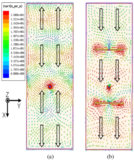
Figure 3: Vector current distribution with phase information of long rectangular microstrip patch: (a) antenna I and (b) antenna II.
B. Evolution of antenna design
In the first step, as shown in Fig. 2 (a), antenna I is a long rectangular microstrip patch, which is a simple coaxial back-feeding method. Compared with the conventional half-wavelength patch antenna, the design of the long rectangular patch antenna permits the distribution of multiple half-wavelength-length radiation units on the patch.
Due to the multi-period electromagnetic distribution on the patch antenna, there must be an anti-phase current. The anti-phase current will affect the radiation efficiency of the antenna, causing destructive interference with the in-phase current in the far-field region, affecting the radiation mode of the antenna, thereby cutting down the gain of the antenna. Next, on the basis of antenna I, a pair of narrow rectangular slots is loaded about half a wavelength away from the center of the patch, that is, the two slots are approximately one wavelength apart, as shown by antenna II in Fig. 2 (b).
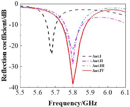
Figure 4: Simulated reflection coefficient of antennas.
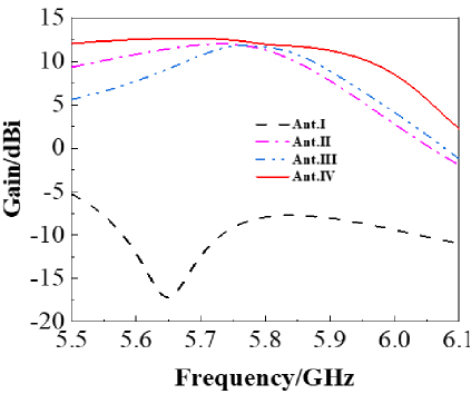
Figure 5: Simulated gain of antennas.
Figure 3 illustrates the distribution of vector currents on the resonant patch. From the arrows marked in Fig. 3 (a), it can be seen that antenna I distributes reverse currents. For the location of the reverse currents, a narrow rectangular slot is added between the co-current and the reverse current so that the reverse currents are forced to be distributed around the rectangular slot, as shown in Fig. 3 (b). At both sides of the rectangular slot, the current flow direction is reversed, so the current on both sides of the slot interacts with each other in the far field region of the antenna, which greatly reduces the influence of the reverse current. According to equation (1), the electric field E and magnetic field H in the far field region of the antenna are improved after adding the rectangular slot, so the directivity and gain of the antenna are effectively improved. Figure 4 shows the reflection coefficient curves of the antennas of several structures shown in Fig. 2. The reflection coefficient curves of the structure of Fig. 2 (a) are shown in the curve Ant.I in Fig. 4, and the resonance point deviates from 5.8 GHz. The reflection coefficient curves of the structure of Fig. 2 (b) are shown in the curve Ant.II in Fig. 4, and the resonant frequency is adjusted to about 5.8 GHz by choosing the appropriate length and width dimensions of the rectangular slot, L18.5 mm and W 0.5 mm. The reflection coefficient curve of the antenna structure in Fig. 2 (c) is curve Ant.III in Fig. 4. A slight degradation appears in the performance of curve Ant.III that is primarily due to the implementation of circular polarization, which leads to a decrease in the reflection performance. Four small rectangular microstrips are added in Fig. 2 (d), as shown in the position of the dotted box. Resonance frequency 5.8 GHz belongs to the Industrial, Scientific, and Medical (ISM) frequency band, which does not cause interference to other communication systems and is one of the best frequency points for wireless power transmission. Moreover, the electrical length corresponding to 5.8 GHz is smaller than that of free frequency bands such as 2.45 GHz, which can reduce the size of the antenna. From Fig. 5, it can be observed that at the frequency of 5.8 GHz, the gain of antenna II has increased to 11.4 dB compared with antenna I. The curve Ant.IV indicates the gain simulation curve of the final structure of the proposed antenna with a gain of 11.9 dB at working frequency of 5.8 GHz.
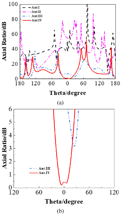
Figure 6: Simulated axial ratio of (a) antennas I-IV and (b) antennas III and IV.
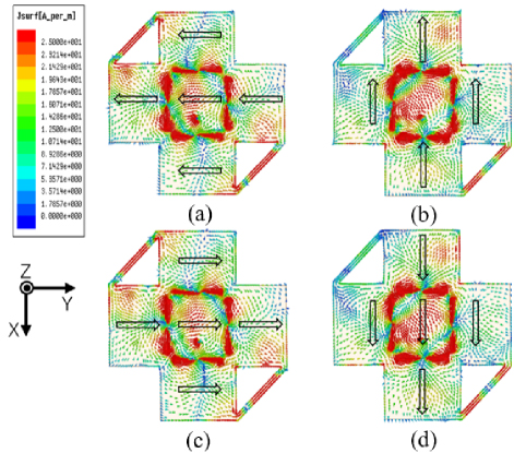
Figure 7: Current distribution of the proposed antenna for (a) phi0, (b) phi90, (c) phi180 and (d) phi270.
C. Implementation of CP characteristics
An antenna must be capable of simultaneously radiating two signals that are of equal amplitude, orthogonal to each other, for achieving CP characteristic in the far field. The resonant current direction of antenna II is towards the x-axis in the Fig. 3 (b). To ensure that there is resonant current along the y-axis direction as well, the antenna II is rotated by 90 around the center point of the patch, forming a cross-shaped patch antenna. In order to achieve circular polarization, a pair of narrow microstrips are loaded at the edge of the cross patch along the direction of the antenna -45 diagonal, as shown in antenna III in Fig. 2 (c). To reduce the axial ratio (AR) value of the proposed antenna at 5.8 GHz, two rectangular microstrips with small dimensions are added at both terminals of the narrow microstrip line, as shown in Fig. 2 (d). The purpose of this design is to increase the current flow path and change the current phase difference between the two rectangular patches along the x-axis and the y-axis direction to optimize the AR value. It is also worth noting that, compared to antenna III, the resonant frequency point of the antenna will be shifted by 5.8 GHz due to the structural change of antenna IV. Therefore, antenna IV also needs to adjust the distance of the two pairs of resonant slots distributed along the x- axis and y-axis from the center of the patches, respectively. Finally, the structure parameter of D is chosen to be 24.5 mm while D is 23.5 mm, as shown in Fig. 1.
The changes in the AR curve during evolution process of the antenna structure in Fig. 2 are shown in Fig. 6 (a). The AR curves Ant.I and Ant.II are greater than 50 dB when theta is equal to zero. After adopting the structure of Fig. 2 (c), the AR of the antenna is greatly reduced without affecting the gain of the antenna. However, the AR value of the antenna is still higher than 3 dB, and further design is still needed to improve the circular polarization AR. From Fig. 6 (b), it is obvious that, compared to AR curve Ant.III, the AR of curve Ant.IV is reduced to less than 3 dB while its resonance frequency and gain remain the same.
Figure 7 demonstrates the distribution of the current on the surface of the patch antenna for phi=0, 90, 180, and 270, respectively. The arrows mark the main direction of the current on the patch. Observing along the reverse direction of the electromagnetic wave propagation direction, it is obvious from Fig. 7 that the vector currents show a clockwise rotation tendency, and thus the antenna has the characteristic of left-hand circular polarization. Similarly, according to the symmetry property of the antenna, if a pair of narrow microstrip lines are loaded in the 45 direction of the patch antenna and similarly observed along the reverse direction of the electromagnetic wave propagation direction, the currents will show a tendency to rotate counterclockwise, and the antenna will have the characteristic of right-hand circular polarization.
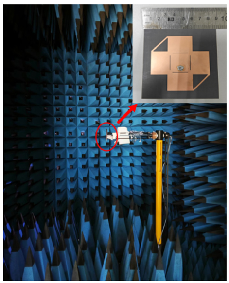
Figure 8: Prototype of the proposed antenna and its measurement setup.
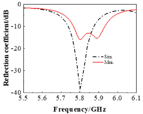
Figure 9: Simulated and measured reflection coefficient for proposed antenna.
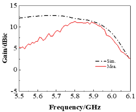
Figure 10: Simulated and measured gain for proposed antenna.
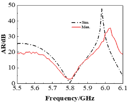
Figure 11: Simulated and measured AR for proposed antenna with changing frequency.
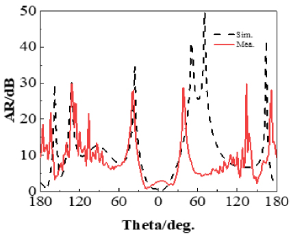
Figure 12: Simulated and measured AR for proposed antenna with changing theta.
IV. ANTENNA MEASUREMENTS AND DISCUSSION
To verify the performance of the designed antenna, the antenna was fabricated on the F4BM substrate. The antenna is measured in a microwave anechoic chamber with the setup shown in Fig. 8. The structure parameter values of the fabricated antenna samples are consistent with the data listed in Table 1. Figures 9 to 12 show the simulated and measured reflection coefficient curves, realized gain, and AR curves of the antenna. In Fig. 9, the measured reflection coefficient has obvious frequency shifts and the reflection deterioration. After discussion and analysis, the main reason may be due to machining accuracy or material tolerances during the production and welding process of the antenna, as well as errors brought about by the adapter, which can lead to the actual matching performance decreases and resonance changes, thus causing frequency shifts and reflections to increase. The simulated and measured 10 dB impedance bandwidth (S11-10 dB) is 2.2% (5.74-5.87 GHz) and 2.8% (5.77-5.93 GHz), respectively. Figure 10 shows the simulated and measured gain curves. The measured maximum gain reaches 11.3 dB at the operating frequency of 5.8 GHz. The measured maximum gain is slightly lower than the simulated gain, which may be due to the tolerance of the antenna fabrication and the loss of electromagnetic energy during the testing process. Additionally, as depicted in Fig. 10, there is a notable difference between the simulated and measured gain within the 5.5-5.7 GHz frequency band. This variation may stem from the antenna’s structural properties changing at the frequency of near 5.5 GHz, which impacts the measured outcomes, as well as potential measurement errors that could occur during the testing process. The antenna designed in this article focuses on wireless power transmission at the working frequency of 5.8 GHz, so the matching of the antenna mainly concentrates on the around 5.8 GHz frequency point. The difference between simulation and actual measurement from 5.5 GHz to 5.7 GHz is mostly caused by impedance mismatch and other factors. However, since the antenna designed in this article is specifically targeted for the 5.8 GHz frequency, the impact of such differences can be disregarded. Figures 11 and 12 show the AR curves of the antenna for frequency variation and theta variation, respectively. The simulated and measured 3 dB AR bandwidths are both 0.52% (5.78-5.81 GHz). The proposed antenna maintains good circular polarization characteristics at 5.8 GHz.
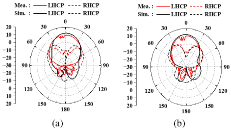
Figure 13: Radiation pattern of antenna at 5.8 GHz: (a) xoz plane and (b) yoz plane.
Figure 13 shows the simulated and measured radiation of the proposed CP antenna in the xoz and yoz planes. At the center frequency of 5.8 GHz, Fig. 13 (a) is the co-polarization (LHCP) pattern and cross-polarization (RHCP) pattern in the xoz plane. Figure 13 (b) is the co-polarization (LHCP) pattern and the cross-polarization (RHCP) pattern in the yoz plane. It can be seen that the measured LHCP gain is more than 20 dB higher than the corresponding RHCP gain in Fig. 13. Therefore, the designed CP antenna has clear LHCP characteristics. Although there are minor differences between the measurements and simulations, their overall agreement is acceptable. The minor differences may be mainly attributed to manufacturing tolerances and experimental measurement errors.
Table 2: Comparison of recently reported antennas for microwave wireless power transmission
| Ref. | OverallSize() | Polarization | r | Gain(dBi) | Impedance BW (GHz)/FBW | 3 dB AR BW(GHz)/FBW |
| [14] | 4.454.454 | LP | - | 13.4 | 5.3-6.3(17.24%) | - |
| [15] | 1.931.930.075 | CP | 2.2 | 8.5 | 5.53-6.06(9.14%) | 5.74-5.89(2.58%) |
| [16] | 2.0849.170.06 | CP | 10 | 5.87 | 5.77-5.85(1.38%) | 5.74-5.84(1.72%) |
| [17] | 2.182.180.04 | CP | 3.55 | 3.8 | 5.75-5.92(2.93%) | 5.77-5.84(1.21%) |
| This work | 1.741.740.029 | CP | 2.2 | 11.3 | 5.77-5.93(2.8%) | 5.78-5.81(0.52%) |
Table 2 provides a detailed comparison of the high-gain CP antenna proposed in this paper with the antenna performance reported in the existing literature. Since both the impedance bandwidth and the 3 dB AR bandwidth include the key frequency of 5.8 GHz, the antenna designed in this study is highly suitable for MPT. Compared to other antennas for MPT detailed in Table 2, the antenna designed here is more compact in size. Furthermore, although the antennas described in [16–18] are all CP, the antenna proposed in this paper utilizes gain enhancement techniques. This results in a gain that is 2.8-7.5 dB higher than that of other CP antennas, which is beneficial for improving the efficiency of MPT.
V. CONCLUSION
In this study, a novel gain-enhanced CP microstrip patch antenna is proposed. The gain of the antenna is enhanced by loading two narrow rectangular slots to the conventional rectangular microstrip patch. The microstrip patch is rotated by 90 to form a cross microstrip patch antenna. Meanwhile, some microstrip structures are added at the edges to change the flow direction of the current to implement the CP characteristic. The position of the two pairs of narrow rectangular slots is slightly adjusted to fine-tune the resonant frequency without affecting other characteristics.
The experimental measurements show that the antenna gain reaches 11.3 dB and AR reaches 2.73 dB at the resonant frequency of 5.8 GHz, which satisfies the performance requirements of high gain and CP for use in microwave power transmission antennas. The design method and experimental results of this study provide valuable references for the antenna design of future microwave transmission systems. It not only provides new tools and solutions for the development of microwave transmission technology but also brings new research ideas and development directions in the field of antenna design.
ACKNOWLEDGMENT
This work was supported by the Fujian Natural Science Foundation Project (2022J01823) and Xiamen Science and Technology Subsidy Project (2024CXY0314).
REFERENCES
[1] Y. Cao, Y. Cai, W. Cao, B. Xi, Z. Qian, and T. Wu, “Broadband and high-gain microstrip patch antenna loaded with parasitic mushroom-type structure,” IEEE Antennas and Wireless Propagation Letters, vol. 18, no. 7, pp. 1405-1409, July 2019.
[2] X. Zhang, L. Zhu, and Q.-S. Wu, “Sidelobe-reduced and gain-enhanced square patch antennas with adjustable beamwidth under TM03 mode operation,” IEEE Transactions on Antennas and Propagation, vol. 66, no. 4, pp. 1704-1713, Apr. 2018.
[3] K.-D. Hong, X. Chen, X. Zhang, L. Zhu, and T. Yuan, “A slot-loaded high-gain circular patch antenna with reconfigurable orthogonal polarizations and low cross polarization,” IEEE Antennas and Wireless Propagation Letters, vol. 21, no. 3, pp. 511-515, Mar. 2022.
[4] X. Zhang and L. Zhu, “Gain-enhanced patch antennas with loading of shorting pins,” IEEE Transactions on Antennas and Propagation, vol. 64, no. 8, pp. 3310-3318, Aug. 2016.
[5] W. Li, Y. Suo, X. Xu, and Y. Liu, “A gain-enhanced rectangular patch antenna with artificial magnetic conductor ground,” in 2017 IEEE International Symposium on Antennas and Propagation & USNC/URSI National Radio Science Meeting, San Diego, CA, pp. 2177-2178, 2017.
[6] G. Dhaundia and K. J. Vinoy, “A high-gain wideband microstrip patch antenna with folded ground walls,” IEEE Antennas and Wireless Propagation Letters, vol. 22, no. 2, pp. 377-381, Feb. 2023.
[7] G. Cheng, B. Huang, Z. Huang, and L. Yang, “A high-gain circularly polarized filtering stacked patch antenna,” IEEE Antennas and Wireless Propagation Letters, vol. 22, no. 5, pp. 995-999, May 2023.
[8] X. Chen, L. Yang, J.-Y. Zhao, and G. Fu, “High-efficiency compact circularly polarized microstrip antenna with wide beamwidth for airborne communication,” IEEE Antennas and Wireless Propagation Letters, vol. 15, pp. 1518-1521, 2016.
[9] C. S. Ong, M. F. Karim, L. C. Ong, T. M. Chiam, and A. Alphones, “A compact 22 circularly polarized antenna array for energy harvesting,” in 2010 Asia-Pacific Microwave Conference, Yokohama, Japan, pp. 1977-1980, 2010.
[10] A. Verma, M. Arrawatia, and G. Kumar, “Broadband series-fed circularly polarized microstrip antenna array,” in 2020 IEEE International Symposium on Antennas and Propagation and North American Radio Science Meeting, Montreal, QC, Canada, pp. 225-226, 2020.
[11] M. A. Sennouni, J. Zbitou, B. Abboud, A. Tribak, and M. Latrach, “Efficient rectenna design incorporating new circularly polarized antenna array for wireless power transmission at 2.45GHz,” in 2014 International Renewable and Sustainable Energy Conference (IRSEC), Ouarzazate, Morocco, pp. 577-581, 2014.
[12] K. Ding, C. Gao, T. Yu, D. Qu, and B. Zhang, “Gain-improved broadband circularly polarized antenna array with parasitic patches,” IEEE Antennas and Wireless Propagation Letters, vol. 16, pp. 1468-1471, 2017.
[13] V. Rafii, J. Nourinia, C. Ghobadi, J. Pourahmadazar, and B. S. Virdee, “Broadband circularly polarized slot antenna array using sequentially rotated technique for C-band applications,” IEEE Antennas and Wireless Propagation Letters, vol. 12, pp. 128-131, 2013.
[14] C. Chen, B. Zhang, and K. Huang, “Nonuniform Fabry-Perot leaky-wave antenna with flat-topped radiation patterns for microwave wireless power transmission,” IEEE Antennas and Wireless Propagation Letters, vol. 18, no. 9, pp. 1863-1867, Sep. 2019.
[15] D. M. Nguyen, N. D. Au, and C. Seo, “Aperture-coupled patch antenna with flat-top beam for microwave power transmission,” IEEE Antennas and Wireless Propagation Letters, vol. 21, no. 10, pp. 2130-2134, Oct. 2022.
[16] D. Surender, Md. A. Halimi, T. Khan, F. A. Talukdar, B. K. Kanaujia, and K. Rambabu, “Analysis of facet-loaded rectangular DR-rectenna designs for multisource RF energy-harvesting applications,” IEEE Transactions on Antennas and Propagation, vol. 71, no. 2, pp. 1273-1284, Feb. 2023.
[17] M. Chang, J. Han, Y. Li, X. Ma, H. Liu, and L. Li, “Self-powered polarization-reconfigurable rectenna for wireless power transfer system,” IEEE Transactions on Antennas and Propagation, vol. 71, no. 8, pp. 6297-6307, Aug. 2023.
BIOGRAPHIES

Ziyang Jiang was born in 2002 in Fujian Province, China. He is currently pursuing his B.S. degree with the Department of Communication Engineering at Jimei University, Fujian Province, China. His research interests are circularly polarized antenna technology and rectenna technology.

Zhonghua Ma was born in Gansu, China, in 1973. He received his Ph.D. in Microelectronics from Lanzhou University in 2018. His present research interests include the antenna techniques, RF circuits design, WPT and IoT.

Xiaojing Sun was born in 2004 in Hebei Province, China. She is currently pursuing her B.S. degree with the Department of Communication Engineering at Jimei University, Fujian Province, China. Her research interests are in microwave technology and rectenna technology.

Weiqian Liang was born in Heilongjiang Province, China, in 1977. He received his Ph.D. in Electronic Science and Technology from Tsinghua University in 2006. His current research interests include signal processing, deep learning and embedded systems.

Haitao Xing was born in 1983 in Shandong, China. In 2010, he obtained a master’s degree in communication and information engineering from Ningbo University. At present, his main research interests are embedded system, artificial intelligence and Internet of Things.
ACES JOURNAL, Vol. 39, No. 12, 1073–1081
doi: 10.13052/2024.ACES.J.391206
© 2024 River Publishers