Research on Electromagnetic Interference of Liquid Crystal Display Screen on Low-medium Speed Maglev Trains
Yutao Tang, Xin Li, and Chao Zhou
Institute of Electronic and Electrical Engineering
Civil Aviation Flight University of China, Guanghan 618307, China
835578907@qq.com, lixin@cafuc.edu.cn, zc_cafuc@163.com
Submitted On: August 23, 2024; Accepted On: December 12, 2024
ABSTRACT
Low-medium speed maglev trains might suffer from electromagnetic interference (EMI) during operation, which is specifically manifested as a blurred image on the liquid crystal display (LCD) screens of the passenger information system (PIS). In order to study the characteristics of the EMI, firstly, the working principle of PIS is analyzed in response to the fault phenomenon of the LCD screens. Possible interference sources are studied. Research results indicate that the leakage magnetic field generated by the transverse end effect of linear motors is the main interference source causing LCD screen faults. Secondly, the coupling mechanism of the EMI is analyzed. Results show that the transverse end effect can cause an increase in the ground potential of the LCD screen casing, resulting in a blurred image on the LCD screen. Finally, the EMI suppression method by suspending and grounding the LCD screen is proposed and its feasibility is verified. In this paper, we comprehensively study the EMI of LCD screens, which provides a theoretical basis for solving the tangible faults of maglev trains.
Index Terms: Coupling mechanism, electromagnetic interference, interference suppression, transverse end effect.
I. INTRODUCTION
The layout of electrical and electronic equipment in low-medium speed maglev trains (speeds of 80 km/h to 100 km/h) are complex. Moreover, the electromagnetic coupling relationship between cables, equipment, and vehicle body is also complicated [1]. Therefore, maglev trains are highly likely to generate electromagnetic interference (EMI) problems, which impact the electronic equipment of trains, such as the liquid crystal display (LCD) screen of the passenger information system (PIS) [2]. Thus, it is important to study the EMI of low-medium speed maglev trains.
Existing research is not comprehensive. Some researchers have conducted research on the electromagnetic environment of urban rail transit [3–5]. Electromagnetic noise around the maglev train was tested and the frequency range of the noise and its impact on the communication system of nearby high-speed trains was determined in [6–8]. EMI source and related models of low-medium speed maglev trains was studied in [9–13]. In response to the interference problem of LCD screens of the PIS, Wen Zheng and others briefly described the excitation sources of electromagnetic radiation (EMR) generated by the LCD screen and analyzed the interference coupling mechanism and fault reasons of it [14, 15]. Chen and Zhou proposed a method for estimating electromagnetic compatibility (EMC) products by analyzing the current spectrum of LCD screen driver power supplies [16]. The EMI problem of LCD screens on subways was studied, and interference suppression schemes were proposed in [17, 18]. The above studies mostly focus on LCD screens on subways. There is limited research on EMI of equipment for low-medium speed maglev trains.
This paper focuses on a fault case of LCD screens in the PIS of low-medium speed maglev trains and studies the EMI of the LCD screen. Firstly, the driving principle of the LCD screen in PIS is analyzed based on the working principle of PIS. Secondly, the interference source and its coupling mechanism are researched, and it is found that the transverse end effect of the linear motor is the main interference source causing LCD screen faults. In addition, the induced voltage generated in the closed circuit between the LCD screen and the control system is simulated and calculated. Thirdly, a classification study is conducted on the suppression methods of the EMI. Finally, an EMI suppression scheme by using diodes in forward and reverse series connection for LCD screen suspension grounding is proposed and verified. The research results of this paper can provide a theoretical basis for solving EMI faults in LCD screens on low-medium speed maglev trains.
II. FAULT ANALYSIS OF LCD SCREENS
A. Working principle of LCD screens
The PIS on the low-medium speed maglev train is computer-based and utilizes a network platform to display real-time dynamic information to passengers through LCD screens. It includes information on emergency situations and guiding passengers to evacuate. Therefore, the LCD screens must clearly display relevant information to ensure normal operation and safety.
The driving circuit of the LCD screen and the values of its resistance, inductance, and capacitance are shown in Fig. 1. The power supply ranges of each voltage in the drive circuit are shown in Table 1.
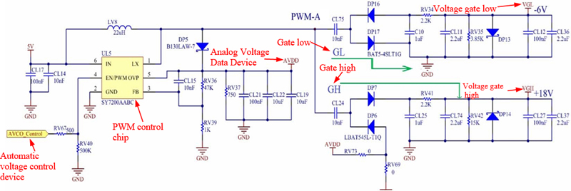
Figure 1: Driving circuit of an LCD screen.
Table 1: Power supply range of each voltage in the LCD screen drive circuit
| Name | Circuit Voltage | VGH | VGL | AVDD |
| Power Range (V) | 5 | 1522 | -610 | 812 |
Firstly, the automatic voltage control device (AVCO) provides the corresponding working voltage to the PWM control chip to output a PWM square wave matrix. When point PWM-A is at a high level, the DP17 in the GL circuit is conductive and CL75 is charged by point A, causing the voltage on the left side of GL to rise to the value of the analog voltage data device (AVDD). When point A is at a low level, the voltage on the right side of GL becomes the negative value of AVDD. Secondly, DP16 is conductive, and the voltage is divided by RV34 and RV35, making the value of the voltage gate low (VGL) equal to -6 V. When the PWM pulse wave at point A is in its initial cycle, CL24 in the GH circuit is charged through DP6. Due to the fast-charging speed, the voltage difference between the left and right sides of GH during low pulse cycles is equal to the value of AVDD. When point A is at high voltage, due to the voltage difference on both sides of CL24 not being able to suddenly change, the voltage on the right side of GH becomes twice the voltage value of AVDD. At this point, DP7 is conducting and the voltage is distributed between RV41 and RV42, making the voltage gate low (VGH) equal to 18 V. The above principle is to achieve LCD screen imaging by controlling the voltage values on both sides of GH and GL.
B. Overview of fault
During the operation of the low-medium speed maglev train, the LCD screen of the PIS may have unclear screen images, which are manifested as thin lines, flickers, or snowflakes in the displayed images. Figure 2 is a simplified model of a maglev train, where MC1 and MC2 are carriages with drivers.
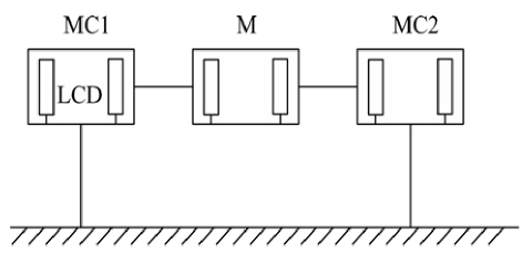
Figure 2: Simplified model of a maglev train.
It can be seen that the train has a total of three carriages, each equipped with two LCD screens. The outer shells of the LCD screens are grounded through the vehicle body.
Based on the working principle of LCD screens and combined with the complex electromagnetic environment of the low-medium speed maglev train, we now study interference sources and their coupling methods.
III. ANALYSIS OF EMI COUPLING MECHANISM ON LCD SCREENS
A. Analysis of interference sources
EMI sources of low-medium speed maglev trains include collector shoes, linear motors, suspension electromagnets, train metal casings, and power and lighting systems [19]. The interference sources and their causes are shown in Table 2. The EMI generated by 1⃝ mainly affects the electromagnetic environment outside the train, and the EMR generated by 2⃝ and 5⃝ is very weak. Therefore, those three sources have almost no impact on the LCD screen.
Table 2: Interference sources and their causes of EMI
| Source | Cause | |
| 1⃝ | Collector shoes | Spark discharge generated by friction and instantaneous poor contact |
| 2⃝ | Train metal casings | EMR caused by reflection |
| 3⃝ | Driving system | Strong magnetic field generated by linear motors |
| 4⃝ | Suspension system | Strong magnetic field generated by suspended electromagnets |
| 5⃝ | Power and lighting systems | EMR at the inlet and outlet of wires |
The suspension system consists of three modules: coil, magnetic yoke, and track [20]. Its simulation model is shown in Fig. 3.
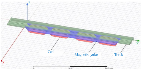
Figure 3: Simulation model of the suspension system.
By simulating the suspension system, the magnetic induction intensity of the coil, track, and yoke can be obtained separately, as shown in Figs. 4, 5, and 6, respectively.
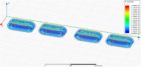
Figure 4: Distribution of magnetic induction intensity of the coil.
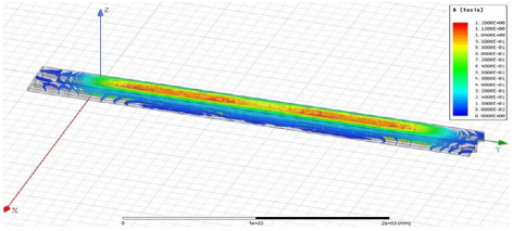
Figure 5: Distribution of magnetic induction intensity of the track.
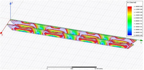
Figure 6: Distribution of magnetic induction intensity of the magnetic yoke.
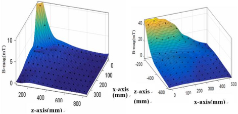
Figure 7: Simulation diagram of magnetic induction intensity changing with distance.
Figures 4, 5, and 6 show that the DC magnetic field of the suspension system is relatively large in the magnetic yoke and the middle of the track. In order to study the EMI of the suspension system, the relationship between the magnetic induction intensity of the above two positions and distance can be studied. The research results are shown in Fig. 7.
According to the simulation results, when the distance from the suspension electromagnet exceeds 400 mm, the magnetic induction intensity will be very weak. Most electronic devices on maglev trains are more than 0.65 m away from the suspension electromagnet. Thus, the impact of EMI generated by 4⃝ on the LCD screen can be ignored. Because the cables for the electronic equipment of the train are laid under the carriage, and the distance between the carriage bottom and the linear motor is very close (about 650 mm), this paper will focus on studying the impact of EMI generated by the driving system 3⃝ on the LCD screens.
B. Magnetic field analysis of linear motors
In the ideal model of a linear motor, the primary of the motor is region 1 (Reg. 1), the air gap between the primary and secondary of the motor is region 2 (Reg. 2), the secondary of the motor is region 3 (Reg. 3), and the part below the secondary is region 4 (Reg. 4). In the following equations, the subscripts x, y, and z represent the x-direction, y-direction, and z-direction. The subscripts 1, 2, 3, and 4 represent Reg. 1, Reg. 2, Reg. 3, and Reg. 4, respectively.
Assuming there is no free charge, the vector magnetic potential A of the linear motor is [20]:
| (1) |
where and are the magnetic permeability and electrical conductivity, respectively. v is the speed of magnetic field movement.
Assuming A is in the z-direction:
| (2) |
where is the angular frequency and is the phase constant.
Because , equation (1) can be rewritten as:
| (3) |
where v is velocity of the air gap magnetic field generated in the Reg. 1, and s is the slip ratio.
The boundary conditions are:
| (4) |
where h is the thickness of Reg. 3, and B and H are the magnetic induction intensity and magnetic field intensity, respectively.
Let us assume:
| (5) |
According to equations (3-5) and , the magnetic induction intensity Bof Reg. 3 can be solved:
| (6) |
Based on the above analysis, the magnetic field of each region of the linear motor can be obtained, and the distribution of its magnetic field will be simulated next.
There are five linear motors on both sides of each carriage of the maglev train The parameters of the linear motors are shown in Table 3.
Table 3: Parameters of the linear motor
| Name | Data | Name | Data |
| Current | 300 A | Excitation frequency | 120 Hz |
| Core height | 120 mm | Gap between the bottom of the train and the track | 13 mm |
| Polar distance | 225 mm | Winding form | Stacked |
| Number of conductors per slot | 6 | Thickness of steel reaction plate | 4 mm |
| Thickness of aluminum reaction plate | 20 mm | Core thickness | 220 mm |
Based on the dimensional data shown in Table 3, a model of the linear motor is established in ANSYS Maxwell 3D simulation software. Firstly, when selecting materials, the iron cores on the primary and secondary sides are made of silicon steel sheets (Model: DW465-50), and the material of the reaction plate is aluminum. Secondly, add three-phase current excitation (phase current: 300 A; excitation frequency: 120 Hz) to the primary winding of the linear motor. We then assign mesh operation (on selection: maximum element length 1.5 mm; inside selection: maximum element length 2 mm). Finally, the magnetic field strength and magnetic induction strength of the linear motors can be simulated and calculated as shown in Fig. 8.
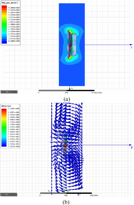
Figure 8: Simulation results of a linear motor: (a) simulation results of magnetic field strength and (b) simulation results of magnetic induction intensity.
As shown in Fig. 8, there is magnetic field leakage in the end winding of the linear motor. The magnetic field strength between the motor winding of the linear motor and the air gap is 510 A/m. The closer it is to the end, the stronger the magnetic field.
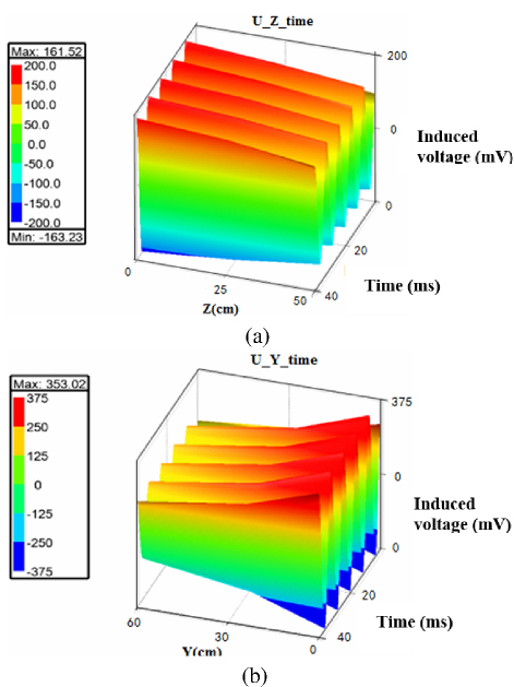
Figure 9: Diagram of the variation of induced voltage with distance from the linear motor: (a) diagram of the variation of induced voltage with Z-axis distance and (b) diagram of the variation of induced voltage with Y-axis distance.
In order to further investigate the interference caused by the leakage magnetic field generated by the end winding of the linear motors, a metal conductor, having a length of 800 mm and a diameter of 4.5 mm, is set horizontally along the X-axis in the simulation model of a linear motor. The influence of the magnetic field of the linear motor on the equipment will be manifested through the inductive terminal voltage of the conductor. Changing the distance between the conductor and the linear motor can reflect the strength of the magnetic field of the linear motor at different positions. The simulation results are presented in Fig. 9.
As shown in Fig. 9, the closer the conductor is to the linear motor, the greater the induced voltage. When the distance changes along the Z-axis, the maximum induced voltage is 161.52 mV. When the distance changes along the Y-axis, the maximum induced voltage is 353.02 mV. Based on simulation outcomes, when the five linear motors operate simultaneously, taking the worst-case scenario into account, induced voltage at a distance of 650 mm from the linear motor is approximately 3.4 V, which will give rise to certain interference to the wire. In conclusion, the leakage magnetic field produced by the linear motor is the main interference source of the LCD screen malfunction.
C. Analysis of the interference coupling mechanism
A simple model of an LCD screen and the linear motor of a low-medium speed maglev train is presented in Fig. 10. There are two LCD screens in one carriage, located at points A and B. There are five linear motors on each side, which convert DC 1500 V into three-phase AC power via the traction converter.

Figure 10: Simplified diagram of an LCD screen and a linear motor.

Figure 11: Schematic diagram of an LCD screen affected by the EMI of a linear motor.

Figure 12: Simulation model of linear motor and closed circuit.
The secondary of the linear motor of the maglev train is wider than the primary, leading to the phenomenon of magnetic flux diffusion on the upper and lower sides and resulting in alteration of the air gap magnetic field. Since the train LCD screen control system cable is mainly longitudinally wired along the bottom of the car, when the linear motor passes through a large current, the magnetic field will influence the closed circuit composed of the adjacent equipment. Hence, the horizontal end effect of the linear motor of the maglev train is the main interference factor causing a malfunction of the LCD screen.
When a large current passes through the linear motor, the magnetic field generated by the lateral end effect will induce a magnetic flux in the circuit consisting of the LCD screen and the control system located 650 mm away from the linear motor. This will subsequently generate an induced voltage at the LCD screen port. The induced voltage will cause the ground potential of the LCD screen housing to rise, resulting in a fault. The inductive coupling model of the LCD display subjected to linear motor EMI is presented in Fig. 11. The device on the left is the casing of the LCD display, and Z represents its equivalent impedance. The device on the right is the casing of the LCD screen control system, and Z represents its equivalent impedance.

Figure 13: Simulation diagram of magnetic field strength.

Figure 14: Graph of induced voltage on a closed circuit.
These two devices are connected by cables laid under the train, forming a common grounding circuit that is 8 m long and 0.4 m wide. The induced voltage U generated by the magnetic field of the linear motor in the closed circuit of the LCD screen control system is:
| (8) |
where B is the magnetic induction intensity of a linear motor and S is the area of a closed circuit.
A simulation model of the magnetic field generated by the combined action of five linear motors passing through the circuit consisting of the LCD screen and the control system is depicted in Fig. 12. The length of the linear motors is approximately 10 m, the length of the closed circuit is about 8 m, and the width is nearly 0.4 m. The simulation result of the magnetic field strength of one of the linear motors is shown in Fig. 13.
As depicted in Fig. 13, the magnetic field strength between the primary winding of the linear motor and the secondary aluminum plate is extremely high, attaining 1.02610 A/m, which generates the driving force to propel the train. When five linear motors operate concurrently, the leakage magnetic field resulting from the lateral end effect induces voltage within the closed circuit formed by the LCD screen casing and the control system, illustrated in Fig. 14.
Based on simulation outcomes, the peak value of the induced voltage produced by the magnetic field resulting from the joint operation of five linear motors within a closed circuit is approximately 2.7 V.

Figure 15: Interference waveform of an LCD screen.

Figure 16: Implementation diagram of suppression measures.
The connection cable between the LCD screen and the control system is arranged along the card slot at the bottom of the train. The card slot is fabricated from steel material with a shielding coefficient k of 0.45 [21]. Therefore, based on the actual situation, the induced voltage U of the closed circuit should be corrected to:
| (9) |
After correction, the peak value of the induced voltage U generated by the magnetic field of the five linear motors acting together on the closed circuit is about 1.215 V. Therefore, the grounding potential of the LCD screen is raised by 1.215 V by simulation calculation.
A digital oscilloscope model GDS-2302A is used to measure the ground voltage of the LCD screen housing on site. The average speed of the train was 100 km/h and the effective value of phase current flowing in the motor was 300 A during the measurements. The test results are shown in Fig. 15. The test results show that peak voltage is below 1.4 V. The induced voltage value calculated by simulation is very close to the actual measured value. It further indicates that the malfunction on the LCD screen is mainly caused by the leakage magnetic field generated by the transverse end effect of the linear motors.
IV. RESEARCH ON SOLUTIONS TO MALFUNCTIONS
In order to solve the fault of the LCD screen caused by the unbalanced grounding potential of the LCD screen casing, this paper uses TVS diodes to suspend the grounding of the LCD screen. Its working principle is that when the circuit is running normally, the TVS is in a high impedance state and does not affect normal operation of the LCD screen. When an abnormal overvoltage emerges in the circuit and attains breakdown voltage, the TVS quickly switches from the off state to the on state. This provides a conductive path for instantaneous current, while also controlling overvoltage within a safe range (within normal operating voltage and maximum clamp voltage), thus protecting the circuit of the equipment. When the abnormal overvoltage vanishes, the TVS returns to the cutoff state.
The maximum voltage for the operation of the LCD screen is 22 V. Consequently, the TVS diode model P6KE24A is chosen, which has a reverse breakdown voltage of 25 V and a maximum clamping voltage of 33 V. Because the EMI encountered by LCD displays is AC interference, it is necessary to connect two TVS diodes in opposite directions in series to suspend the grounding of LCD screen.
As depicted in Fig. 16, two P6KE24A TVS diodes are connected in series at the signal grounding screw hole of the LCD display screen. The TVS diode is connected to the LCD screen casing through a signal grounding screw and suspended for grounding. Subsequently, an oscilloscope is used to measure the ground voltage of the LCD screen housing on site, and the test results are shown in Fig. 17.

Figure 17: Interference waveform of the LCD screen after adding suppression measures.
Comparing Figs. 15 and 17, it can be seen that the induced voltage is significantly suppressed after the TVS diode is connected in series. After using this method, the malfunction of the LCD screen disappeared.
V. CONCLUSION
The malfunction of an LCD screen on a low-medium speed maglev train is studied in this paper. The conclusions are as follows:
(1) The leakage magnetic field generated by the end winding of the linear motor is the cause of LCD screen failure.
(2) The leaked magnetic field will generate induced voltage in the closed circuit connected between the LCD screen and the control system by inductive coupling, thereby generating EMI on it.
(3) The technique of utilizing two TVS diodes in series to suspend and ground the LCD display screen is an effective method for suppressing EMI.
ACKNOWLEDGMENT
The authors would like to thank the editors and anonymous reviewers for their insightful comments. This paper is supported by the Natural Science Foundation of Sichuan, China (NO. 2024NSFSC0866) and the Fundamental Research Funds for the Central Universities (No. PHD2023-005).
REFERENCES
[1] S. Niska, “A major source of faults in Swedish railway,” International Journal of Perform Ability Engineering Electromagnetic Interference, vol. 5, no. 2, pp. 187-196, 2009.
[2] H. Wang and W. Xue, “Development and application of the railway transportation management information system,” Applied Mechanics and Materials, vol. 26, no. 1, pp. 1848-1851, 2013.
[3] J. Hu, “Analysis of characteristics of traction power supply system for medium and low speed maglev vehicles,” Electric Locomotives & Mass Transit Vehicles, vol. 26, no. 4, pp. 33-34, 2003.
[4] B. Tellini, M. Macucci, and R. Giannetti, “Conducted and radiated interference measurements in the line-pantograph system,” IEEE Transactions on Instrumentation and Measurement, vol. 50, no. 6, pp. 1661-1664, 2001.
[5] Y. Tang, F. Zhu, H. Lu, and X. Li, “Analysis and suppression of EMI for traction control unit speed sensors of CRH380BL electric multiple unit,” Applied Computational Electromagnetics Society Journal, vol. 33, no. 5, pp. 553-560, 2018.
[6] Y. Wu, “Test and research on electromagnetic interference of maglev vehicle,” Railway Signaling & Communication, vol. 44, no. 2, pp. 24-26, Feb. 2008.
[7] B. Wei, K. Yu, and Y. Duan, “Study on the electromagnetic interference of low medium speed maglev on high speed railway GSM-R communication,” Railway Signaling & Communication, vol. 51, no. 7, pp. 48-52, 2015.
[8] H. Qi, “Analysis of electromagnetic environment in the operation of middle and low speed maglev vehicle,” Electric Drive for Locomotives, pp. 62-65, May 2012.
[9] G. Yang and Z. Zhao, “Comparative study on several typical rail transit operation control systems,” Journal of the China Railway Society, vol. 31, no. 1, pp. 82-87, 2009.
[10] Y. Chen and X. Tian, “The development of the linear induction motor,” IEEE Transactions on Newcomen Society, vol. 67, no. 1, pp. 185-205, 2014.
[11] W. Xu, “System-level efficiency optimization of a linear induction motor drive system,” IEEE Transactions on Electrical Machines and Systems, vol. 3, no. 3, pp. 285-291, 2019.
[12] R. Luo, J. Wu, and Z. Li, “Research on the electromagnetic interference of the environment space where the levitation gap sensor of the medium and low speed maglev vehicle is located,” Instrument Technique and Sensor, vol. 67, no. 1, pp. 1-6, Nov. 2018.
[13] J. Ding, X. Yang, and Z. Long, “Structure and control design of levitation electromagnet for electromagnetic suspension medium speed maglev vehicle,” IEEE Transactions on Vibration and Control, vol. 25, no. 6, pp. 1179-1193, 2019.
[14] W. Zheng, W. Hu, and L. Zhou, “Design of passenger information system suitable for medium and low speed maglev vehicle,” Electric Locomotives & Mass Transit Vehicles, vol. 37, no. 2, pp. 22-25, 2014.
[15] Z. Liang, J. Zhu, and J. Zhang, “Research and improvement of green TFT-LCD,” Chinese Journal of Liquid Crystals and Displays, vol. 34, no. 4, pp. 354-360, 2019.
[16] M. Chen and F. Zhou, “The design and implementation of a low cost 360-degree color LCD display system,” IEEE Transactions on Consumer Electronics, vol. 37, no. 2, pp. 735-739, 2011.
[17] S. Kim and H. Choi, “Application of cascode level shifter for EMI reduction in LCD driver IC,” IEEE Transactions on Electronics Newsweekly, vol. 3, no. 1, pp. 321-325, 2015.
[18] L. Su, X. Yang, and X. Li, “Research on the mechanism and improvement of high-temperature reliability crosstalk of automotive TFT-LCD devices,” Journal of Optoelectronics, vol. 39, no. 2, pp. 123-126, 2019.
[19] Z. Hu and Y. Wu, “Environmental impact analysis and protective measures of Harbin rail transit phase project,” Journal of Environmental Science and Management, vol. 32, no. 8, pp. 81-84, 2007.
[20] Y. Chen, “Typical electromagnetic interference of vehicle PIS system coupling mechanism and suppression study,” M.S. thesis, Southwest Jiaotong University, Chengdu, China, 2021 [in Chinese].
[21] TB/T 1678-1997, Railway Industry Standard of the People’s Republic of China: Professional Terminology for Communication Protection of AC Electrified Railway. Beijing: China Railway Press, 1997.
BIOGRAPHIES

Yutao Tang was born in Sichuan Province, China, in 1991. She received the Ph.D. degree in electrical engineering at Southwest Jiaotong University, Chengdu, China, in 2021. She is currently a Lecturer in the Institute of Electronic and Electrical Engineering, Civil Aviation Flight University of China. Her research interests include electromagnetic environment test and evaluation, and electromagnetic compatibility analysis and design.

Xin Li received the Ph.D. degree in electrical engineering from Southwest Jiaotong University, Chengdu, China. He is currently a research associate in the Civil Aviation Flight University of China, Chengdu, China. His current research interests include electromagnetic compatibility analysis, evaluation, transmission line analysis, rail traffic, civil unmanned aerial vehicles, and navigation technology research.

Chao Zhou was born in AnHui, Province, China, in 1980. He received his Ph.D. degree from University of Electronic Science and Technology of China in 2013. He is working in Civil Aviation Flight University of China, where he is currently a professor, deputy dean of the Institute of Electronic and Electrical Engineering, master tutor, and head of the UAV team. His current research interests include civil unmanned aerial vehicles and civil aviation electromagnetic environment effects.
ACES JOURNAL, Vol. 39, No. 12, 1116–1124
doi: 10.13052/2024.ACES.J.391210
© 2024 River Publishers