Time-domain Hybrid Method for the Coupling Analysis of Curved Power Lines Illuminated by Early-time High-altitude Electromagnetic Pulse
Zhihong Ye, Zhiwei Gao, Guangzhi Hong, Chen Tong, Ziran Ji, and Zeyu Xiao
1State Key Laboratory of Power Grid Environmental Protection
Wuhan 430070, China
yezh@cqupt.edu.cn
2School of Communication and Information Engineering
Chongqing University of Posts and Telecommunications, Chongqing 400065, China
3368652883@qq.com, 3055215238@qq.com, 851904800@qq.com, 2765567579@qq.com
3School of Information Science and Technology
Shijiazhuang Tiedao University, Shijiazhuang 050043, China
gao_zhiwei@163.com
Submitted On: August 22, 2024; Accepted On: November 27, 2024
ABSTRACT
An efficient time-domain field-to-line hybrid method is presented to realize the rapid coupling calculation of curved power lines (CPLs) illuminated by Early-Time (E1) high-altitude electromagnetic pulse (HEMP). Firstly, improved transmission line equations are derived by ideal conductor boundary conditions and transmission line theory, which are employed to construct the E1 HEMP coupling model of CPLs. Then, based on the image principle, a rapid calculation method for the excitation fields of CPLs is investigated, and improved transmission line equations are solved by the finite-difference time-domain (FDTD) method to achieve fast iterative calculation of voltage and current responses along CPLs. Finally, relevant numerical simulations are utilized to verify the accuracy and efficiency of the proposed method. On this basis, the impact of power line lengths, heights, and ground electromagnetic parameters on E1 HEMP coupling of CPLs is analyzed.
Index Terms: Early-Time high-altitude electromagnetic pulse coupling of curved power lines, finite-difference time-domain method, improved transmission line equations, rapid calculation method for the excitation fields of curved power lines.
I. INTRODUCTION
High-altitude electromagnetic pulse (HEMP) is divided into three stages: Early-Time (E1), Intermediate-Time (E2), and Late-Time (E3). The E1 stage of HEMP has the significant features of high energy, broad bandwidth, and long duration, which can generate strong induced voltages and currents on overhead power lines that can damage or disable their terminal electronic equipment, and even threaten the safety of the national power grid [1–4]. Moreover, power lines are curved configurations affected by gravity. Therefore, studying the coupling problems of E1 HEMP to curved power lines (CPLs) can provide valuable data support for the design of the national power grid under nuclear radiation environment.
Due to the wide radiation coverage of E1 HEMP and long lengths of power lines, full-wave algorithms cannot be directly adopted to simulate the E1 HEMP coupling effects of power lines. To avoid modeling the fine structures of power lines, researchers have conducted numerous numerical algorithms based on transmission line equations. The Baum-Liu-Tesche (BLT) equation [5] and the finite-difference time-domain (FDTD) method [6] are the most widely used.
The radiation mechanism of E1 HEMP was explored in [7], and the BLT equation has been employed to compute E1 HEMP coupling responses on power lines. Additionally, the influence of incidence angles of E1 HEMP and power line heights on the coupling responses of power lines has been extensively investigated using the BLT equation [8, 9]. The same method was combined with an artificial neural network to predict E1 HEMP coupling voltages on power lines [10]. However, the BLT equation is a frequency-domain method, yielding single-frequency point responses per calculation. Thus, its efficiency will be low when applying it to the coupling simulation of power lines excited by E1 HEMP.
The fundamental principle underlying the FDTD solution of transmission line equations is to construct the coupling model of power lines using either transmission line equations of the Taylor model or Agrawal model. These models are subsequently discretized by FDTD’s central difference scheme to calculate the voltage and current responses along power lines iteratively. This methodology has been widely applied for the coupling calculations of power lines illuminated by lightning [11–13] and nuclear electromagnetic pulses [14]. However, these studies focus on power lines in a straight configuration; the curved characteristics of power lines is neglected.
In our previous work, transmission line equations of the Agrawal model combining with the coordinate transformation technique have been investigated to build the coupling model of multi-directional CPLs, and the voltage and current responses on CPLs subjected to lightning electromagnetic pulses was calculated by the FDTD method [15]. Although the FDTD method can obtain transient voltage and current responses at any point of power lines and achieve higher efficiencies for broadband field-to-line coupling problems, the Taylor model requires the integration of vertical electric field components between power lines and the ground to derive the equivalent distributed sources of transmission line (TL) equations, resulting in high computational complexity. Similarly, the Agrawal model requires the integration of vertical electric field components at both ends of power lines to determine the corresponding incident voltages and, consequently, total voltages at the loads. In addition, within these methods, the analytical formulas of incident wave and reflected wave are used to obtain the total electric fields at FDTD grid nodes of power lines, and then convert to it time-domain via Inverse Fast Fourier Transform (IFFT). This operation needs considerable computation time when the lengths of power lines are long.
Therefore, improved transmission line equations, enhanced by the rapid calculation method of excitation fields of CPLs, are presented to address the limitations of classical transmission line methods in coupling calculations of CPLs excited by E1 HEMP. The advantages of the proposed method are that the constraints associated with the use of vertical electric field components in classical transmission line equations are overcome, and the rapid calculation of E1 HEMP coupling responses on long CPLs is achieved.
II. COUPLING MODEL OF E1 HEMP TO CURVED POWER LINES
A. Improved transmission line equations
Since the material of power lines is a good conductor, the total electric field along the surface of CPLs is zero, as shown in Fig. 1, expressed as:
| (1) |
where and are incident electric field and scattered electric field, respectively.
According to transmission line theory, the coupling model of E1 HEMP to CPLs can be treated as a cascade network of power line units represented by a distributed parameter circuit, as shown in Fig. 1. Since the inductive and capacitive effects of CPLs are more prominent [16], the resistance lossy of power lines is neglected in this paper. The scattered electric fields along CPLs can be regarded as equivalent voltage sources, which are added to each power line unit as excitation source.
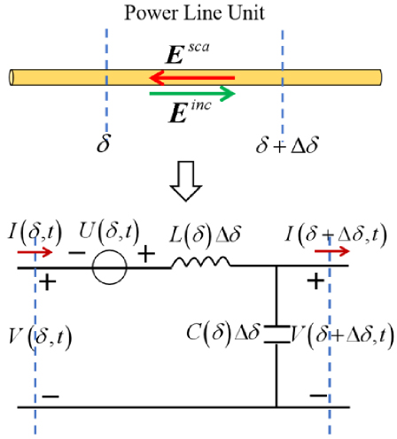
Figure 1: Distributed parameter circuit of power line unit.
Here we take one CPL as an example to explain the establishing process of improved transmission line equations. For each power line unit, the voltage and current equations for its distributed parameter circuit are listed based on Kirchhoff’s Current Law (KCL) and Kirchhoff’s Voltage Law (KVL), expressed as:
| (2) | ||
| (3) |
where represents the direction of power line (PL) and represents the length of the PL unit. and are the voltage and current at the beginning port of the PL unit, respectively. and are the voltage and current at the ending port of the PL unit, respectively. and represent the per unit length (PUL) inductance and capacitance of the PL unit, respectively. is the equivalent voltage source term of the PL unit, expressed as:
| (4) |
If both sides of equations (2) and (3) are divided by , and letting , they will be translated to the improved transmission line equations, expressed as:
| (5) | ||
| (6) |
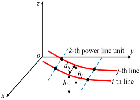
Figure 2: Solution model for the distribution parameters of the k-th power line unit.
It must be emphasized that the forms of equations (2) and (3) are similar to the transmission line equations of the Agrawal model, while the voltages in these equations stand for total voltages rather than scattering voltages. Furthermore, equations (5) and (6) can be extended to multiple CPL cases, and expressed as:
| (7) | ||
| (8) |
where and are the voltage and current vectors on CPLs, respectively. is the excitation field vector obtained from the incident electric fields along CPLs. and are the PUL inductance and capacitance matrices of CPLs, respectively. They can be calculated by the empirical formulas from [15], expressed as:
| (9) | ||
| (10) |
where is the radius of the i-th line of the k-th power line unit. stands for the distance between the i-th and j-th lines of the k-th power line segment. and are the center position heights of the i-th and j-th lines of the k-th power line unit, respectively, as shown in Fig. 2. and are the permittivity and permeability of free space, respectively.
B. Rapid calculation method for the excitation fields of power lines
The modeling precision of improved transmission line equations is significantly dependent on the accurate calculations of excitation fields and the PUL distributed parameter matrices of power lines. E1 HEMP can be regarded as a plane wave due to its wide coverage area of thousands of kilometers and its propagation over several tens of kilometers before reaching the ground. Because the excitation fields of power lines are influenced by the ground’s reflection, they should be calculated by the superposition of incident electric fields of E1 HEMP and its reflected electric fields caused by the ground [17].
To avoid directly modeling the infinite ground structure and to obtain the excitation fields of power lines in the time-domain, the effect of the ground on E1 HEMP is equivalent to a time-domain reflected wave source based on image principle. The calculation process for the three electric field components of the time-domain reflected wave source is described as follows.
Firstly, the E1 HEMP is decomposed into three electric field components , and under the Cartesian coordinate system, as shown in Fig. 3, and expressed as:
| (11) |
where is the amplitude of E1 HEMP at time t, and ,, and are the incident angle, azimuth angle, and polarization angle of E1 HEMP.
Next, Fast Fourier Transform (FFT) is performed on the electric field components , , and to obtain , , and . These frequency domain electric field components are multiplied by the corresponding horizontal and vertical polarization reflection coefficients of the ground to get the three frequency-domain electric field components of the reflected wave source, named , , and . Specifically, they are expressed as , , and , where and are the vertical and horizontal polarization reflection coefficients of the ground [15], respectively, and expressed as:
| (12) | ||
| (13) |
where is the angle between the incident wave and the normal direction of the ground, which is complementary to the incident angle , and and are the conductivity and relative permittivity of the ground, respectively.
Finally, , , and are converted to time-domain by the IFFT to obtain the three electric field components of the reflected wave source , , and .
As shown in Fig. 3, the positions of the time-domain reflected wave source and the incident wave source are symmetric about the ground. The electric fields at any point above the ground can be obtained by superimposing the electric fields of the incident wave source and the reflected wave source after corresponding propagation time delay, which are expressed as , where , , and are the propagation distances from incident wave source and reflected wave source to the same point above the ground, respectively.
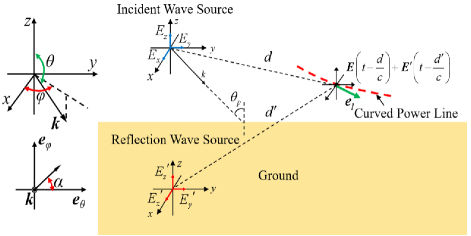
Figure 3: Rapid calculation of the excitation fields of curved power lines.
Considering the curved feature of power lines, the incident electric field components along CPLs should be calculated by , thereby obtaining the equivalent distributed source term of improved transmission line equations, where represents the direction vector of each power line unit.
C. FDTD solution of improved transmission line equations
In this section, the improved transmission line equations will be solved by the FDTD method. According to the difference scheme of FDTD, power lines should be divided into N segments by FDTD space step firstly. The voltages and currents along the power lines are alternately sampled in time and space, as shown in Figs. 4 and 5, where the voltage and current nodes are staggered by half-space step in the space domain and by half-time step in the time-domain.
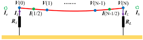
Figure 4: Spatial sample scheme of voltages and currents on power lines.
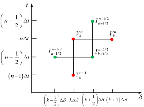
Figure 5: Temporal sample scheme of voltages and currents on power lines.
The improved TL equations are discretized by the central difference scheme of one-dimensional FDTD, expressed as:
| (14) | ||
| (15) |
Let us rearrange (12) and (13) to obtain the iteration formulas of current and voltage responses on CPLs, which are written as:
| (16) | |||
| (17) |
Currents and are missing, as shown in Fig. 4, thus the voltages at starting and ending ports of power lines do not satisfy the usage condition of FDTD’s central difference scheme [18, 19]. Under the circumstance, forward difference and backward difference [20] are applied to solve these voltages, respectively, which are expressed as:
| (18) |
| (19) |
Voltages and currents at starting and ending ports of power lines should satisfy Ohm’s law, which are expressed as:
| (20) | ||
| (21) |
Substituting equations (18) and (19) into equations (C.) and (17), and further arranging to obtain the iterative formulas of voltages at starting and ending ports:
| (22) | ||
| (23) |
where and represent the load matrices of the starting port and ending port, respectively.
In summarize, the iteration process of this hybrid method contains four important steps. Firstly, calculating the excitation electric fields along CPLs at n-time step to obtain the distributed source term vector of (C.). Secondly, calculating the current responses along CPLs at n+1/2-time step via (C.). Thirdly, calculating the voltage responses along CPLs at n+1-time step via (17). Finally, the port voltages of CPLs at n+1-time step are calculated via (22) and (23).
III. NUMERICAL SIMULATION
To confirm the correctness and efficiency of the time-domain hybrid method, E1 HEMP coupling problems of three horizontally aligned transmission lines with different lengths and heights are simulated by the proposed method and method of moments (MoM), and comparing their results in terms of simulation precision and computation time. On this basis, this method is applied for the E1 HEMP coupling effect analysis of power line lengths, heights, and electromagnetic parameters of the ground.
A. Correctness verification
Figure 6 is the coupling model of three curved transmission lines on the perfect conductor (PEC) ground illuminated by E1 HEMP. The radius, length, height, and line distance of transmission lines are r 5 mm, l 50 m, h 3.6 m, and d 3 m, respectively. The sag height of the lines is set as s 0.9 m. The terminal loads of transmission lines are all matching loads of 359.24 . The E1 HEMP is defined by the IEC standard [21] and illuminates the transmission lines with incident angle 180, azimuth angle 90, and polarization angle 180. Its waveform is expressed as , where V/m, s, and s.
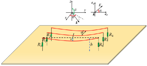
Figure 6: Coupling model of three curved transmission lines on the PEC ground.
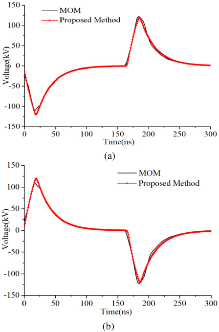
Figure 7: Voltage responses on the loads obtained by the two methods for first case: (a) voltages on load R1 and (b) voltages on load R4.
The voltage responses on loads R1 and R4 calculated by the time-domain hybrid method and MoM are shown in Fig. 7. Here, the transmission lines are divided into 500 segments by the FDTD grid in our method, and 1500 segment grids are required by MoM to mesh the structures of transmission lines. Meanwhile, the results of MoM are transformed to time-domain via IFFT. We can observe that the results of the two methods are in good agreement.
To further verify the efficiency of this method, the computation times required by the proposed method and MoM are compared, with 8 s and 1080 s, respectively. It can be seen that the proposed method can significantly reduce computation time due to the benefit of without direct modeling fine structures of transmission lines.
Based on the above case, the lengths and heights of transmission lines are changed to 100 m and 5.6 m, respectively. In the same way, the E1 HEMP coupling of transmission lines is calculated via the proposed method and MoM, and their results are compared from two aspects of precision and computation time to enhance the confidence of this method. Further, 1000 FDTD grids and 3000 segment grids are required by the proposed method and MoM, respectively.
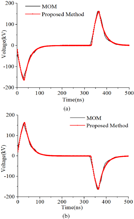
Figure 8: Voltage responses on the loads obtained by the two methods for second case: (a) voltages on load R1 and (b) voltages on load R4.
It can be observed from Fig. 8 that the results obtained by the two methods agree well. In addition, the computation time needed by the proposed method and MoM is 13 s and 3700 s, respectively. It means that the efficiency of this method will increase with an increase in transmission line length.
B. E1 HEMP coupling effect analysis of power lines
To facilitate the nuclear electromagnetic protection design of power lines, three phase power line models are employed to illuminate the influences of power line lengths, heights, and ground electromagnetic parameters on the E1 HEMP coupling effect of CPLs.
1. Effect of power line lengths
To evaluate power line lengths on the coupling effect of CPLs, the simulation of E1 HEMP to 10 kV three-phase power lines on the lossy ground is taken into account, as shown in Fig. 9, where the relative permittivity and conductivity of the ground are 10 and 0.01 S/m, respectively. The power lines are all LGJ150/25 steel core aluminum stranded wires, with equivalent radius of 8.55 mm, height of 10 m, and line distance of 3 m. Meanwhile, the maximum sag and horizontal span of CPLs are s 1.2 m and l 150 m, respectively. The terminal loads are all set as 50 to indicate the port impedance of equipment connected to CPLs. E1 HEMP also illuminates CPLs vertically, with incident angle 180, azimuth angle 0, and polarization angle 180.
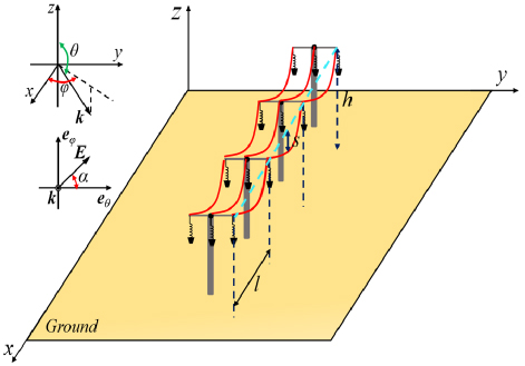
Figure 9: Coupling model of 10 kV three phase power lines on the loss ground.
The current responses at the center of middle line of CPLs are calculated via the proposed method with lengths of 150 m, 300 m, 450 m, and 600 m, respectively, as shown in Fig. 10. It can be seen that the peak values of currents on CPLs will remain constant with increasing of power line lengths when the lengths of power lines are long enough, but the oscillation periods of currents increase.
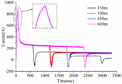
Figure 10: Current responses at the center of power lines with different lengths.
2. Effect of power line heights
Due to different voltage levels of power lines having different heights from the ground, it is necessary to discuss the influence of power line heights on the coupling effect of power lines. Based on the above case of 10 kV three-phase power lines, their lengths are fixed as 150 m, and five different heights are selected for analysis, with 5 m, 8 m, 10 m, 12 m, and 15 m, respectively. In the same way, the proposed method is employed to calculate the current responses at the center of middle line of CPLs with corresponding heights, as shown in Fig. 11.
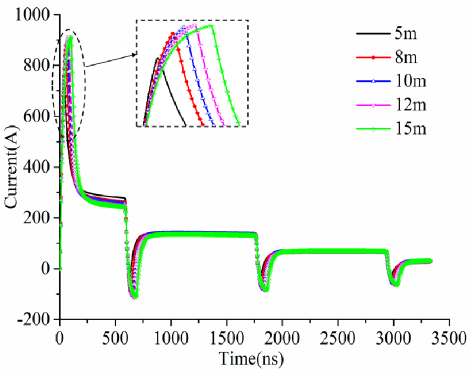
Figure 11: Current responses at the center of power lines with different heights.
It is evident that as the heights of CPLs increase the peak values of current responses also increase. However, the relationship between CPL heights and peak values of these current responses are non-linear, because the synthetic electric fields of incident wave and its ground reflection wave along CPLs are changed with increasing of CPL heights. This effect gradually diminishes as the CPL heights increase to over 10 m.
3. Effect of ground conductivity
Ground electromagnetic parameters, especially conductivity, are quite different in different regions. To conduct the influence of ground conductivity on E1 HEMP coupling effect of CPLs, the 10 kV three-phase power lines is also employed, which have fixed length and height, with 150 m and 10 m, respectively. The relative permittivity of the ground is set as 10, and four different ground conductivity parameters are selected for analysis, with 1 S/m, 0.1 S/m, 0.01 S/m, and 0.001 S/m, respectively.
Figure 12 is the current responses at the center of middle line of CPLs calculated by the proposed method in term of these ground conductivity. It is obvious that the influence of ground conductivity on E1 HEMP coupling effect of CPLs can be ignored.
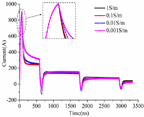
Figure 12: Current responses at the center of power lines with different ground conductivity.
IV. CONCLUSION
A time-domain hybrid method applied for the fast calculation of E1 HEMP to CPLs has been developed. Within this method, the improved transmission line equations are derived first, which can effectively reduce the complexity inherent of traditional field-to-line coupling methods. Then, a rapid calculation method for the excitation fields of power lines is presented, which can raise the calculating rate of the proposed method. Finally, the FDTD method is adopted to solve the TL equations to obtain transient voltage and current responses on power lines. Compared with other algorithms, the advantages of the proposed method are that it has improved the transmission line equations to decrease the solving complexity of equivalent sources of TL equations and has achieved rapid coupling calculation of long CPLs. Numerical simulations of E1 HEMP to three curved transmission lines have been employed to demonstrate that the proposed method achieves the same calculation accuracy as the full-wave algorithm while reducing much computation time. Moreover, the effects of power line lengths, heights, and ground electromagnetic parameters on E1 HEMP coupling of actual CPLs have been investigated, which can provide valuable guidance for the design of nuclear radiation protection of power lines.
ACKNOWLEDGMENT
This work is supported by the Open Fund of State Key Laboratory of Power Grid Environmental Protection (Grant No. GYW51202301435).
REFERENCES
[1] V. N. Greetsai, A. H. Kozlovsky, V. M. Kuvshinnikov, V. M. Loborev, Y. V. Parfenov, and O. A. Tarasov, “Response of long lines to nuclear high-altitude electromagnetic pulse (HEMP),” IEEE Trans. Electromagn. Compat., vol. 40, no. 4, pp. 348-354, Nov. 1998.
[2] R. Hoad and W. Aradasky, “Progress in high-altitude electromagnetic pulse (HEMP) standardization,” IEEE Trans. Electromagn. Compat., vol. 55, no. 3, pp. 532-538, June 2013.
[3] W. A. Radasky, “The potential impacts of three High Power Electromagnetic (HPEM) threats on smart grids,” IEEE Electromagnetic Compatibility Magazine, vol. 1, no. 2, pp. 107-110, July 2012.
[4] D. V. Giri and W. D. Prather, “High-altitude electromagnetic pulse (HEMP) risetime evolution of technology and standards exclusively for E1 environment,” IEEE Trans. Electromagn. Compat., vol. 55, no. 3, pp. 484-491, June 2013.
[5] Y. X. Sun, Q. Li, W. H. Yu, Q. H. Jiang, and Q. K. Zhuo, “Study on crosstalk between space transient interference microstrip lines using finite difference time domain method,” Applied Computational Electromagnetics Society (ACES) Journal, vol. 30, no. 8, pp. 891-896, Aug. 2015.
[6] X. Zhou, L. Fan, M. Zhao, and Q. Yang, “Calculation of transient responses of EMP on transmission lines,” in Applied Computational Electromagnetics Society (ACES) Conference, Firenze, Italy, 2017.
[7] E. Savage, J. Gilbert, and W. Radasky, “The early-time (E1) high altitude electromagnetic pulse (HEMP) and its impact on the U.S. power grid,” Report Meta-R-320 for Oak Ridge National Laboratory, 2010.
[8] H. Y. Xie, T. J. Du, M. Y. Zhang, Y. Li, H. L. Qiao, J. Yang, Y. W. Shi, and J. G. Wang, “Theoretical and experimental study of effective coupling length for transmission lines illuminated by HEMP,” IEEE Trans. Electromagn. Compat., vol. 57, no. 6, pp. 1529-1538, Dec. 2015.
[9] H. Y. Xie, Y. Li, H. L. Qiao, and J. G. Wang, “Empirical formula of effective coupling length for transmission lines illuminated by E1 HEMP,” IEEE Trans. Electromagn. Compat., vol. 58, no. 2, pp. 581-587, Apr. 2016.
[10] H. Y. Xie, Y. Liu, Y. Li, and H. L. Qiao, “A prediction model based on artificial neural network for E1 HEMP coupling with distribution power lines,” IEEE Trans. Power Del., vol. 37, no. 6, pp. 5337-5344, Dec. 2022.
[11] S. I. Abouzeid, G. Shabib, and A. Z. Mohamed, “Induced voltages on overhead transmission lines because of nearby included lightning channel,” IET Gener. Transm. Distrib., vol. 9, no. 13, pp. 1672-1680, Oct. 2015.
[12] M. Brignone, D. Mestriner, R. Procopio, A. Piantini, and F. Rachidi, “On the stability of FDTD-based numerical codes to evaluate lightning-induced over-voltages in overhead transmission lines,” IEEE Trans. Electromagn. Compat., vol. 62, no. 1, pp. 108-115, Feb. 2020.
[13] G. K. Ishimoto, F. Tossani, F. Napolitano, A. Borghetti, and C. A. Nucci, “Direct lightning performance of distribution lines with shield wire considering LEMP effect,” IEEE Trans. Power Del., vol. 37, no. 1, pp. 76-84, Feb. 2022.
[14] X. Y. Zhai, H. Y. Xie, H. L. Qiao, J. N. Chen, and C. Yang, “A full-wave-transmission-line hybrid method for vertically laid shielded cable illuminated by HEMP,” IEEE Trans. Electromagn. Compat., vol. 65, no. 5, pp. 1501-1508, Oct.2023.
[15] Z. H. Ye, Y. C. Shi, Z. W. Gao, and X. L. Wu, “Time domain hybrid method for the coupling analysis of power line network with curved and multidirectional segments,” IEEE Trans. Electromagn. Compat., vol. 65, no. 1, pp. 216-224, Feb.2023.
[16] X. Liu, M. Zhang, T. Wang, and Y. Ge, “Fast evaluation of lightning induced voltages of overhead line and buried cable considering the lossy ground,” IET Sci., Meas. Technol., vol. 13, no. 1, pp. 67-73,2019.
[17] R. Huan, C. Liao, Z. H. Ye, and J. Luo, “A time domain hybrid method for the coupling of two wires above the ground excited by electromagnetic pulses,” Microw. Opt. Technol. Lett., vol. 62, no. 3, pp. 1117-1124, Mar. 2020.
[18] A. Taflove, Computational Electrodynamics: The Finite-Difference Time-Domain Method. Boston: Artech House, 2005.
[19] A. Elsherbeni, The Finite-Difference Time-Domain Method for Electromagnetics with MATLAB Simulations. New Jersey: SciTech, 2016.
[20] Y. X. Sun, Q. Li, W. H. Yu, Q. H. Jiang, and Q. K. Zhuo, “Study on crosstalk between space transient interference microstrip lines using finite difference time domain method,” Applied Computational Electromagnetics Society (ACES) Journal, vol. 30, no. 8, pp. 891-897, Aug. 2015.
[21] H. Y. Xie, Y. Li, H. L. Qiao, and J. G. Wang, “Empirical formula of effective coupling length for transmission lines illuminated by E1 HEMP,” IEEE Trans. Electromagn. Compat., vol. 58, no. 2, pp. 1117-1124, Apr. 2016.
BIOGRAPHIES

Zhihong Ye was born in Taixing, Jiangsu Province, China, in 1988. He received the B.S. degree from Southwest Jiaotong University in 2010. He received the Ph.D. degree from Southwest Jiaotong University in 2016. He became an assistant professor of Posts and Telecommunications at Chongqing University in 2018. His research interests include electromagnetic compatibility, electromagnetic protection, and electromagnetic propagation.

Zhiwei Gao was born in Nanyang, Henan Province, China, in 1972. He received the M.Sc. and Ph.D. degrees from Beijing Jiaotong University, Beijing Institute Technology, in 2002 and 2014, respectively. Since 1995, he has worked with the Department of Computer Science and Technology, Shijiazhuang Tiedao University. He became a professor of Shijiazhuang Tiedao University in 2018. His research interests include computational electromagnetics, electromagnetic compatibility, and electromagnetic protection.

Guangzhi Hong was born in Zhongshan, Guangdong Province, China, in 2004. He is studying for the bachelor’s degree of Electronic Information Engineering from Chongqing University of Posts and Telecommunications. His research interest is electromagnetic compatibility.

Chen Tong was born in Yuzhong District, Chongqing, China, in 2002. He is studying for the bachelor’s degree of Communication Engineering from Chongqing University of Posts and Telecommunications. His research interest is electromagnetic compatibility.

Ziran Ji was born in Taizhou, Jiangsu Province, China, in 2002. He is studying for the bachelor’s degree of Data Science and Big Data Technology from Chongqing University of Posts and Telecommunications. His research interest is machine learning.

Zeyu Xiao was born in Beijing, China, in 2004. He is studying for the bachelor’s degree of Electronic Information Engineering from Chongqing University of Posts and Telecommunications. His research interest is electromagnetic compatibility.
ACES JOURNAL, Vol. 39, No. 11, 952–960
doi: 10.13052/2024.ACES.J.391103
© 2024 River Publishers