Design and Analysis of High-thrust Magnetic Field Modulation Transverse Flux Motor for New Energy High-voltage Disconnector
Yi Su, Lei Gao, Wei Huang, Jian Qin, and Yufeng Lu
Guangxi Key Laboratory of Intelligent Control and Maintenance of Power Equipment
Electric Power Research Institute of Guangxi Power Grid Co. Ltd., Nanning 530023, China
935665054@qq.com, suyi935665054@126.com, huang_w.sy@gx.csg.cn, qin_jian@gx.csg.cn, lu_yf.sy@gx.csg.cn
Submitted On: September 2, 2024; Accepted On: January 7, 2025
ABSTRACT
In order to solve the problem of traditional high-voltage disconnector mechanism jamming and improve the thrust of the drive mechanism, a direct-drive magnetic field modulation transverse flux motor (MFM-TFM) is proposed in this paper. First, the three-dimensional structure of MFM-TFM is introduced. The expression of air gap flux density is derived according to the permeability method. The air gap flux density of the lower air gap dominated by the sixth harmonic is modulated into the air gap flux density of the upper air gap dominated by the fifth harmonic. The increase in the amplitude of low-order harmonics can increase the average thrust. Secondly, the upper and lower air gap widths, permanent magnets, iron cores, pole shoes and modulators are optimized. The optimized motor has good no-load back EMF and current waveform sinusoidality. Through core lamination, the loss of the transverse flux motor is effectively reduced. The rated average thrust of the motor reaches 612.54 N. Finally, the prototype was manufactured and the experimental test platform was built. The thrust and back EMF were measured and compared with the experimental values to verify the rationality of the proposed topology and the accuracy of the calculated results.
Index Terms: High thrust, magnetic field modulation, new energy high-voltage disconnector, optimized design, transverse flux motor.
I. INTRODUCTION
Permanent magnet linear synchronous motor (PMLSM) is often used as the core drive mechanism in various circumstances such as aerospace, medical equipment and power systems [1]. PMLSM has the advantages of simple structure and strong reliability [2]. In addition, due to the simple mover structure, PMLSM has a short response time [3]. Compared with the traditional electric excitation motors, PMLSM has no excitation winding copper loss, which makes it more efficient [4].
As a type of permanent magnet motor, servo PMLSM can accurately control the motor speed and movement distance. Therefore, servo PMLSM has important potential in the intelligent development of power systems [5]. In the operation of large power grids, servo motors serve as the driving core of high-voltage disconnectors. The servo motor drives the contact to move through the transmission mechanism to complete the opening and closing actions [6–8]. Since the high-voltage switch operating mechanism is in an inactive state for a long time, the influence of the external environment will cause the components to age [9–11]. At the same time, during the opening and closing process, the contacts often melt due to high temperature [12–14]. When the contacts move again, melting may cause problems such as mechanism jamming [15], which will cause the switch to fail to work. When the instantaneous thrust or torque generated by the servo motor is too small to drive the mechanism to move, the motor cannot rotate. Stalling will cause the motor to heat up severely, which will affect the safe operation of the power grid [16–17]. In addition, due to the low speed of the opening and closing process, the motor has a large power or torque, which will make the motor have a large volume and low power density.
At present, in order to increase the torque or thrust of the motor, the common method is to connect the servo motor to the mechanical gear. Although the mechanical gear has the function of amplifying the torque of the motor, it has friction loss. The gear needs to be frequently repaired and lubricated. Mechanical gears often have problems such as jamming or even freezing, which leads to high maintenance costs [18–20]. In order to increase the thrust or torque of the motor, the direct-drive magnetic field modulation transverse flux motor (MFM-TFM) has attracted much attention. The direct-drive transverse flux motor can be directly connected to the contact without other transmission mechanisms. It has the characteristics of simple structure and high efficiency [21]. At the same time, based on the principle of magnetic field modulation, low-speed motion is converted into high-speed motion of the magnetic field, which effectively improves the power density of the magnetic field modulation motor.
The magnetic flux direction of the transverse flux motor is perpendicular to the direction of motion. The stator part of the motor can be laminated with silicon steel to reduce losses, which can improve the efficiency of the motor. The transverse flux linear motor is combined with a magnetic gear to form an MFM-TFM. In low-speed direct drive applications, the MFM-TFM has the characteristics of high-thrust density or torque density. However, there is no literature published on high-thrust MFM-TFMs for high-voltage disconnectors.
An MFM-TFM is proposed in this paper. Firstly, the three-dimensional structure of the direct-drive MFM-TFM is introduced. According to the permeance method, the air gap magnetomotive force and air gap permeance are given. The expression of air gap flux density is derived. The relationship between the number of low-order working harmonic pole pairs and the low-order working harmonic speed is studied. Secondly, the MFM-TFM structural parameters are optimized and designed. The effects of upper and lower air gap widths, permanent magnets, cores, pole shoes and modulator sizes on back EMF, thrust and thrust fluctuation are studied. The hysteresis loss, eddy current loss and additional loss of laminated core and non-laminated core are calculated and compared. Finally, the prototype is manufactured and the experimental test platform is built. The motor thrust and back EMF are measured and compared with the experimental values, which verifies the rationality of the proposed topology and the accuracy of the calculation results.
II. MFM-TFM TOPOLOGY AND WORKING PRINCIPLE
A. MFM-TFM topology
The three-dimensional structure of the direct-drive field modulation transverse flux motor is given in Figs. 1 and 2. The two-dimensional structure of the MFM-TFM is given in Figs. 3–5. The MFM-TFM mainly includes stator I, stator II and linear mover. Stator I is a segmented structure. The armature windings of phase A, phase B and phase C are installed in the slots of stator I. Inclined magnetic conductive materials and inclined non-magnetic conductive materials are installed in the middle mover. The magnetic conductive material is made of laminated silicon steel to effectively reduce the core loss. The non-magnetic conductive material is made of stainless steel. Stator II mainly has segmented core, PM and excitation winding. The excitation winding can change the size of the excitation magnetic field by changing the excitation current. The permanent magnet and the excitation winding are arranged alternately. Based on the alternating arrangement, the leakage flux can be reduced. The air gap flux density is increased to make the motor power density higher. The detailed dimensional parameters of the MFM-TFM in the front view and oblique view are given in Figs. 6 and 7. The rated parameters and basic size parameters of MFM-TFM are shown in Table 1.
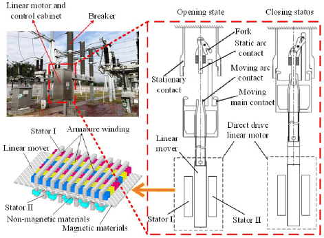
Figure 1: MFM-TFM structure.
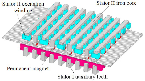
Figure 2: Lower stator side of the 3D structure.
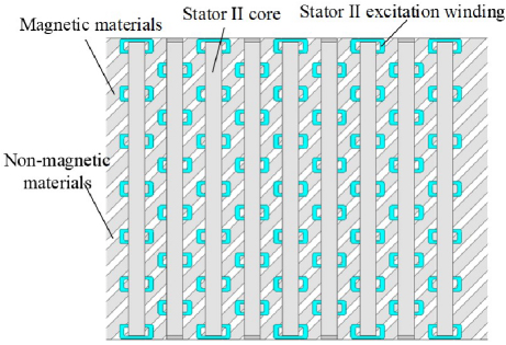
Figure 3: 2D image of the lower stator side.
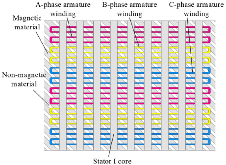
Figure 4: 2D image of the upper stator side.
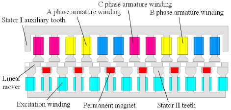
Figure 5: Front view of MFM-TFM.
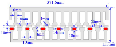
Figure 6: Dimensions of front view.
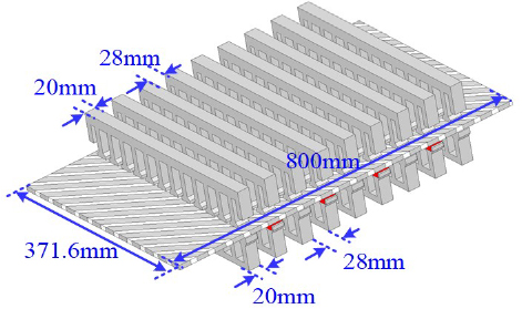
Figure 7: Dimensions of oblique views.
Due to the inclined structure, when the stator moves linearly, the velocity component is generated in the direction of movement and the perpendicular direction of movement. When the mover moves, the changing magnetic flux is generated in the stator I core. The induced electromotive force is generated in the armature winding due to the changing magnetic flux, which is the working principle of MFM-TFM. Therefore, when the stator I armature winding is supplied with alternating three-phase voltage and current, a changing magnetic field is generated in the middle air gap. The mover generates thrust under the action of the magnetic field and moves linearly.
Table 1: Rated parameters of the prototype
| Parameter | Value | Parameter | Value |
| Rated thrust (N) | 612.5 | Rated current (A) | 2 |
| Linear speed (m/s) | 1 | Rated power (W) | 612.5 |
| Modulator pole number | 11 | Upper air gap width (mm) | 1 |
| Upper stator slot number | 12 | Lower air gap width (mm) | 1 |
| Upper stator poles | 10 | Lower stator pole number | 12 |
In the proposed MFM-TFM, the number of magnetic field pole pairs of the stator I armature winding is 5. The number of poles of the modulator is 11. The number of magnetic field pole pairs generated by PM and excitation winding is 6. The ratio of the number of modulator poles to the number of lower stator magnetic field pole pairs is 11:5. Therefore, the transmission ratio of MFM-TFM can be defined as 11:5. According to the magnetic field modulation principle, the speed of the mover is 5/11 of the speed of the stator I armature magnetic field. The thrust of the mover is 11/5 times that of the stator core I. Therefore, the thrust of the mover is effectively amplified. This is the fundamental reason why magnetic field modulation increases the thrust of the motor.
B. Calculation of air gap magnetic flux density based on permeability method
The total permeance per unit area of MFM-TFM can be expressed as:
| (1) |
where is the permeance per unit area of the permanent magnet, is the permeance per unit area of the air gap, is the permeance per unit area of the mover.
In the stator II of the MFM-TFM, the current of the DC excitation winding is adjusted to change the excitation magnetic field. The air gap flux density is adjusted to make the direction of the excitation magnetic field exactly opposite to the direction of the magnetic field generated by the permanent magnet. The total permeance per unit area can be expressed by the Fourier series as equations (2), (3) and (4).
In equations (2), (3) and (4), is the DC part of the permeance per unit area, is the width of MFM-TFM, is the speed of the linear mover, is the initial position of the mover, is the number of effective permeable materials of the modulator, is the permeance of the modulator’s tilted permeable material, is the permeance of the modulator’s tilted non-permeable material, is the width of the modulator’s tilted permeable material, is the width of the modulator’s tilted non-permeable material, is the thickness of the modulator.
The magnetomotive force generated by stator II PM can also be expressed using Fourier series as equations (5) and (6).
In equations (5) and (6), is the residual magnetism of PM, is the number of magnetic field pole pairs generated by PM.
Therefore, the air gap flux density can be expressed as equation (B.):
{strip}
| (2) |
| (3) | ||
| (4) |
| (5) |
| (6) |
| (7) |
Table 2: Harmonic distribution of main air gap magnetic flux density
| Pole Pairs | Speed |
| 0 | |
The main harmonic characteristics of the air gap flux density are shown in Table 2. Since the amplitude of low-order harmonics is much larger than that of high-order harmonics, the average thrust can be increased by increasing the amplitude of low-order harmonics. The relationship between the number of pole pairs of low-order harmonics and the speed is:
| (8) | ||
| (9) |
where is the pole pair number of the working harmonic, is the speed of the working harmonic, is the transmission ratio.
The pole pitch of the working harmonic is:
| (10) |
where is the pole pitch of the working harmonic, is the width of the modulator’s tilted non-magnetic material.
The losses of the proposed MFM-TFM mainly include permanent magnet eddy current loss, core loss and copper loss. By increasing the armature current amplitude, the iron loss, copper loss, output power and efficiency of MFM-TFM are calculated. Iron loss mainly includes hysteresis loss, eddy current loss and additional loss, which can be expressed as:
| (11) |
where , and are the hysteresis loss coefficient, eddy current loss coefficient and additional loss coefficient, , , , , is the maximum magnetic density, is the frequency.
Copper loss can be expressed as:
| (12) |
where is the winding resistance, is the current, is the copper resistivity, is the winding length, is the winding cross-sectional area, is the number of slots, is the number of winding turns.
III. MFM-TFM DESIGN AND OPTIMIZATION ANALYSIS
A. Calculation and analysis of air gap magnetic flux density based on finite element method
The air gap flux before and after modulation is calculated as shown in Figs. 8–11. The lower air gap flux and the upper air gap flux are shown in Figs. 8 and 10. The lower air gap flux in Fig. 8 is transformed by fast Fourier transform (FFT) to obtain the harmonic flux amplitude before modulation as shown in Fig. 9. The upper air gap flux in Fig. 10 is transformed by FFT to obtain the harmonic flux amplitude after modulation as shown in Fig. 11.
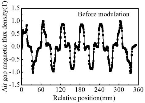
Figure 8: Lower air gap magnetic flux before modulation.
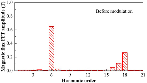
Figure 9: Lower air gap magnetic flux harmonic.
It can be seen in Fig. 9 that the 6th harmonic flux amplitude is the largest. This is mainly because the number of magnetic field pole pairs generated by the permanent magnet and the excitation winding of the lower stator is 6.
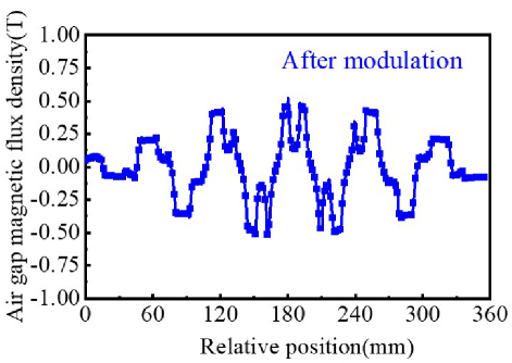
Figure 10: Upper air gap magnetic flux after modulation.
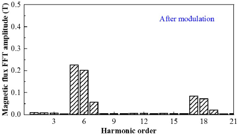
Figure 11: Upper air gap magnetic flux harmonic.
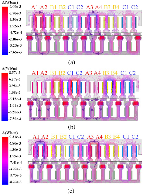
Figure 12: Magnetic flux paths for different mover positions: (a) Position A, (b) Position B, and (c) Position C.
Therefore, the flux in the lower air gap is mainly dominated by the 6th harmonic. That is, before the modulator is applied, the 6th harmonic flux amplitude in the lower air gap is the largest. The number of poles of the modulator is 11.
According to equation (8), in the upper air gap, the 5th harmonic flux amplitude is the largest. In Fig. 11, according to the finite element calculation, the 5th harmonic flux amplitude in the upper air gap is the largest, which is also consistent with the theoretical derivation. Therefore, when the 5th harmonic magnetic field is generated by the upper stator winding, stable energy transfer can be achieved, which is the basic working principle of the proposed MFM-TFM. Therefore, when the number of magnetic field pole pairs generated by the stator I winding is 5, stable power transmission can be achieved.
The distribution of magnetic field lines of the mover at different positions is shown in Fig. 12. At position A, the flux linkage of phase A is maximum. At position B, the flux linkage of phase A is short-circuited. The flux linkage of phase A is 0. At position C, the flux linkage of phase A is maximum in reverse direction.
B. MFM-TFM optimization design and loss calculation
In this paper, a multi-objective optimization algorithm is used to optimize the main parameters of the MFM-TFM. The average thrust, output power and efficiency of the MFM-TFM are focused on. The influence of structural parameters on average thrust and thrust fluctuation needs to be considered comprehensively. The initial structural parameters and optimization design process of the MFM-TFM are shown in Table 3 and Fig. 13. First, the structural parameters of the MFM-TFM are analyzed by correlation to obtain the main structural parameters. According to the parameter variation range in Table 3, the electromagnetic performance of the MFM-TFM is parametrically calculated. The multi-objective optimization algorithm is used to find the optimal solution for the parameter optimization results. Compared with the width of the modulator, the electromagnetic performance of the MFM-TFM is more obviously affected by the modulator length. Although a larger modulator length can reduce thrust fluctuation and increase back EMF within a certain range, the reduction in average thrust is also very obvious. High average thrust and low thrust fluctuation are set as optimization targets. The number of winding turns and slot fill rate are comprehensively considered to obtain the optimized structural parameters as shown in Table 3.
Table 3: Optimization range of the main parameters
| Optimization Parameters | Symbol | Range | Step Length | Final Value |
| PM width | w | 4-14 | 1 | 10 mm |
| Upper stator tooth boots length | l | 16-24 | 2 | 20 mm |
| Modulator length | l | 14-28 | 1 | 20 mm |
| Lower stator tooth boots length | l | 16-24 | 2 | 20 mm |
| Modulator width | w | 3-12.5 | 0.5 | 10 mm |
| PM length | l | 4-30 | 2 | 14 mm |
| Upper stator yoke width | w | 10-24 | 2 | 16 mm |
| Lower stator yoke width | w | 6-14 | 2 | 10 mm |
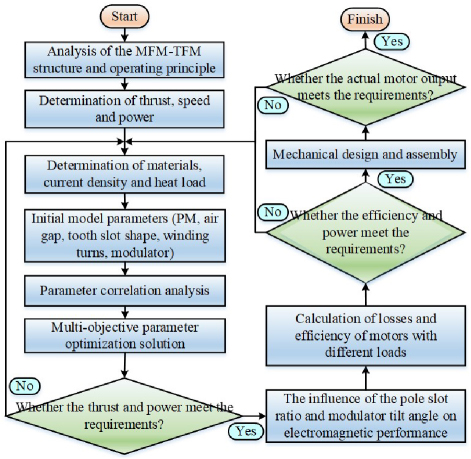
Figure 13: Design and optimization process of the MFM-TFM.
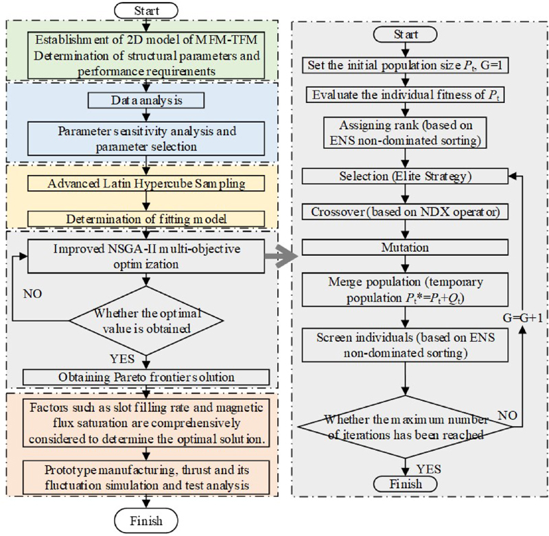
Figure 14: Optimization process based on the improved NSGA-II algorithm.
In this paper, the second-generation non-dominated sorting genetic algorithm-II (NSGA-II) is adopted to optimize the proposed MFM-TFM structure. NSGA-II is an improved version of the non-dominated sorting genetic algorithm (NSGA), which improves the convergence of the algorithm by adopting a fast non-dominated sorting algorithm and a crowding algorithm.
In the design of MFM-TFM, the performance indicators of the MFM-TFM, such as load average thrust and thrust fluctuation, are used as objective functions. The optimization variables mainly include the structural parameters of MFM-TFM, such as permanent magnet shape, modulator shape and tooth slot shape as shown in Table 3. The optimization objectives are mainly the electromagnetic performance of the MFM-TFM, such as maximizing the average thrust and minimizing the thrust fluctuation.
The optimization process based on the multi-objective optimization algorithm is shown in Fig. 14. The specific steps are as follows:
1⃝ The optimization objectives and design variables are determined. The optimization objectives of the designed MFM-TFM are lower thrust fluctuation and higher average thrust.
2⃝ Based on ANASYS Maxwell software, the thrust fluctuation and average thrust data of MFM-TFM with different structural parameters are calculated. The sensitive parameter analysis method is used to calculate and analyze the sensitivity function of the design variables to the optimization objectives. Structural parameters with high sensitivity are selected to generate the required sample points. Based on the sample points, the response surface model is built.
3⃝ The surrogate model is built. According to the sample points, the fitted model is obtained based on Advanced Latin Hypercube Sampling.
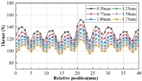
Figure 15: Effect of upper air gap width on thrust of single stator.
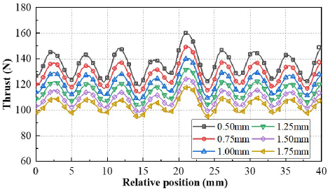
Figure 16: Effect of lower air gap width on thrust of single stator.
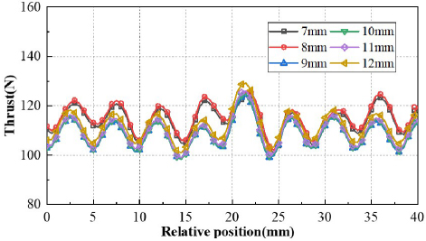
Figure 17: Effect of PM lengths on thrust of single stator.
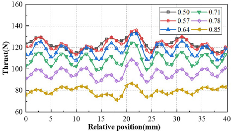
Figure 18: Effect of core widths factor on thrust.
4⃝ The improved NSGA-II algorithm is used to solve the model in step 3⃝. In order to better solve the multi-objective optimization problem of MFM-TFM design, the normal distribution crossover (NDX) operator and the efficient non-dominated sorting (ENS) sorting were adopted. The joint model was built in Maxwell & Workbench & OptiSLang. According to the variable constraints and target requirements, the pareto front solution was generated.
5⃝ The slot fill rate, magnetic flux saturation, slot width and assembly of MFM-TFM were comprehensively considered to determine the final parameters of the design variables. Based on the finite element method, the back EMF, average thrust and thrust fluctuation were calculated and experimentally verified.
The influence of different structural parameters on electromagnetic performance is studied. The motor thrust under different air gap widths is shown in Figs. 15 and 16. It can be seen that as the air gap width increases, the thrust of the modulator decreases. This is because when the air gap increases, the air gap magnetic resistance also increases, and the effective magnetic flux change decreases. So, the thrust also decreases. However, the air gap width needs to consider the performance and assembly difficulty comprehensively. The influence of PM and core width on thrust is given in Figs. 17 and 18. It can be seen that as the width of the permanent magnet increases, the thrust also gradually increases. However, the influence of the width of the permanent magnet on the thrust is not significant. The change of thrust under different width coefficients is given in Fig. 18. It can be seen that when the core width coefficient gradually decreases, the thrust of the mover gradually increases. But the thrust increase rate gradually decreases. When the width coefficient reaches 0.57, the thrust increase gradually reaches saturation.
In order to study which variables have a greater impact on the performance of MFM-TFM, the sensitivity analysis is employed. The sensitivity index can be expressed as:
| (13) |
where is the optimization target response, is the design variable. The load average thrust and thrust fluctuation are the optimization target. Then, the weight coefficient is used to comprehensively evaluate each variable, and the comprehensive sensitivity index G(ni) is introduced, which can be expressed as:
| (14) |
where and are the sensitivity indices of the load average thrust and thrust fluctuation, respectively, and are the weight coefficient of load average thrust and thrust fluctuation. The sum of and is 1.
The objective function is given in equation (15). The range of optimization variables and other constraints are given in Table 3 and equations (16), respectively:
| (15) |
| (16) |
The voltage and current curves of MFM-TFM are given in Figs. 19 and 20. It can be seen that the waveform sinusoidality of the back EMF is relatively high. The waveform sinusoidality of the load current is also relatively high. This shows that the electromagnetic performance of the MFM-TFM proposed in this paper is relatively good. The influence of the modulator, permanent magnet and pole shoe on the electromagnetic performance of the motor is given in Figs. 21 and 22. It can be seen that when the modulator width is 10 mm and the length is 20 mm, the thrust of the mover is relatively high. For thrust fluctuation, it can be seen that the length of the stator I shoe has a greater influence on the thrust fluctuation.
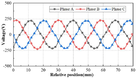
Figure 19: Back EMF of MFM-TFM.
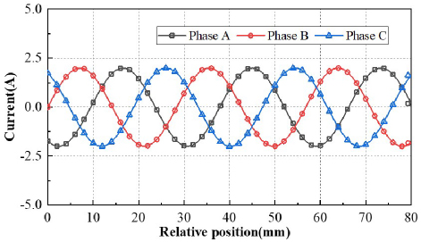
Figure 20: Armature current of MFM-TFM.
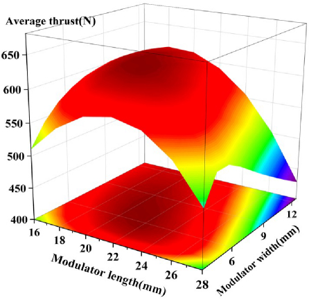
Figure 21: Effect of modulator on average thrust.
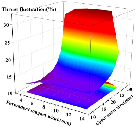
Figure 22: Effect of permanent magnet and stator shoe on thrust fluctuation.
When the length of the stator I shoe gradually increases, the thrust fluctuation also gradually increases. This is mainly caused by the interaction of the tooth slot force. The thrust fluctuation is relatively less affected by the width of the permanent magnet.
For the adopted NSGA-II, the genetic algorithm population size is 200. The crossover probability is 0.8. The mutation probability is 0.02. The number of iterations is 200 generations.
Scatter plots of average thrust and thrust fluctuation of MFM-TFM with different designs are given in Fig. 23. Sensitivity analysis of optimization parameters to average thrust and thrust fluctuation is given in Fig. 24. According to the variation range of MFM-TFM optimization parameters, the thrust fluctuation and average thrust are calculated and analyzed.
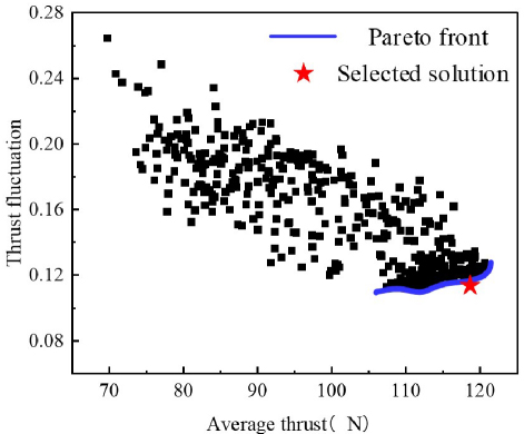
Figure 23: Scatter plots of average thrust and thrust fluctuation of MFM-TFM with different designs.
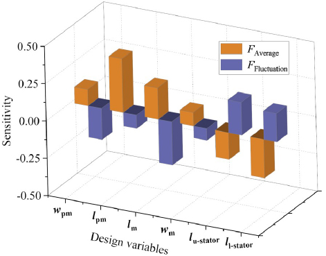
Figure 24: Sensitivity analysis of optimization parameters to average thrust and thrust fluctuation.
In the calculation results, the pareto front solution is obtained. According to the comprehensive sensitivity index, slot filling rate and magnetic flux saturation constraints, the optimized design parameters are determined. For the selected design points, the sensitivity of different optimization parameters to the average thrust and thrust fluctuations are analyzed. In Fig. 24, the sensitivity of the permanent magnet length and the lower stator tooth boots length to the average thrust is relatively large. The sensitivity of the modulator length and the permanent magnet width to the thrust fluctuation is relatively large.
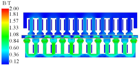
Figure 25: No-load magnetic flux density distribution.
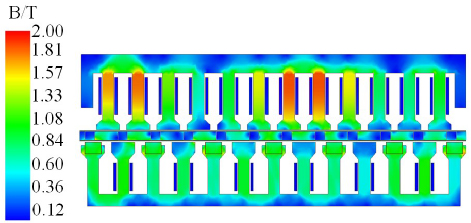
Figure 26: Magnetic flux distribution at rated load.
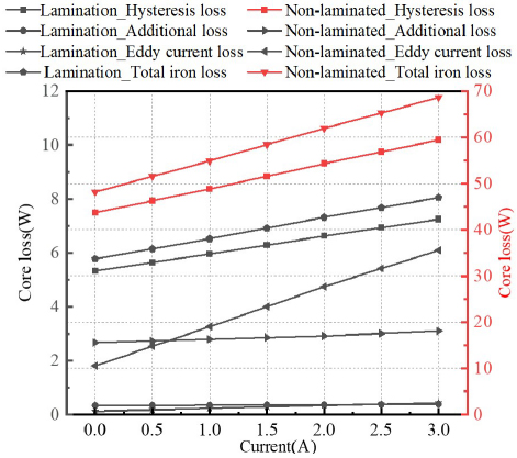
Figure 27: Loss calculation and analysis of single stator.
In order to further verify the stability and reliability of the designed structure, the magnetic flux distribution under no-load and rated-load conditions is shown in Figs. 25 and 26.
Table 4: Comparison of machine performances
| Proposed MFM-TFM | TF-FRLM [22] | TF-PMLM [23] | EDT-PMLSM [24] | CT-PMLSM [25] | |
| Rated thrust (N) | 612.5 | 278.6 | 117.8 | 3335.7 | 2612.9 |
| Rated power (W) | 612.5 | 278.6 | 117.8 | 1214.9 | 951.1 |
| Active volume ( ) | 1.3e-3 | ||||
| Thrust ripple (%) | 17.4 | 34.4 | 2.6 | 5.0% | 8.4% |
| Thrust per active volume ( ) | 98.8 | 153.5 | 91.6 | 87.8 | 68.8 |
| Power per active volume ( ) | 98.8 | 153.5 | 91.6 | 35.2 | 27.1 |
| Efficiency (%) | 81.6 | - | 80.8 | 91.1 | 90.7 |
In Fig. 26, it can be seen that, except for the high magnetic flux saturation of the upper stator teeth, the saturation of most of the motor magnetic flux is low. Therefore, according to the magnetic flux calculation results, it can be seen that the electrical load selection of the MFM-TFM is reasonable.
In order to further study the loss and efficiency of the proposed MFM-TFM, the hysteresis loss, additional loss, eddy current loss and total loss are shown in Fig. 27. It can be seen that as the armature current gradually increases, the loss also gradually increases. Since the stator core is made of laminated silicon steel sheets, the hysteresis loss, additional loss, eddy current loss and total loss are much smaller than those of non-laminated sheets. At the rated current of 2 A, the average thrust of the motor reaches 612.54 N.
In order to reflect the advantages of the structure proposed in this paper, the electromagnetic performance comparison between MFM-TFM and different linear motors is shown in Table 4. When the armature current is 2 A and the mover speed is 1 m/s, the calculated thrust of the mover is 612.5 N. It can be seen from Table 4 that the proposed MFM-TFM has a higher thrust density compared with the conventional PMLSM, which is mainly due to the magnetic field modulation effect of the mover. In addition, the thrust fluctuation of the proposed MFM-TFM is relatively small.
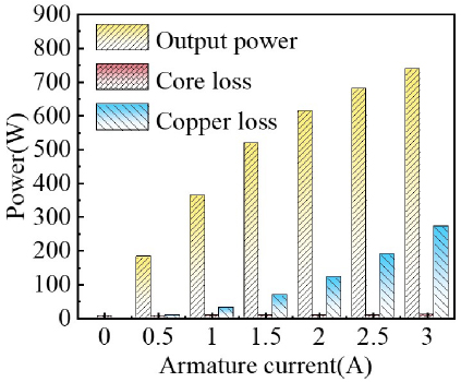
Figure 28: Loss of MFM-TFM with the variation of armature current.
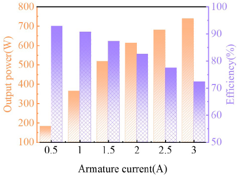
Figure 29: Output power and efficiency of MFM-TFM with the variation of armature current.
The proposed MFM-TFM has two very significant advantages. First, the mover of the ordinary PMSLM is covered with permanent magnets. Due to the high cost of permanent magnets, the manufacturing cost of the motor is very high when the mover is long. However, the mover of the proposed MFM-TFM is made of cheap ferromagnetic materials. The manufacturing cost of the MFM-TFM is lower. The MFM-TFM is very suitable for long stroke applications. Therefore, the MFM-TFM proposed in this article has huge application potential in new energy high-voltage disconnector. Second, based on the modulation effect of the magnetic field, the MFM-TFM has the advantages of high-power density and small thrust fluctuation in low-speed direct driveapplications.
Loss of MFM-TFM with the variation of armature current is given in Fig. 28. Output power and efficiency of MFM-TFM with the variation of armature current are given in Fig. 29. As can be seen from Figs. 28 and 29, the main loss of the motor is copper loss. As the armature current gradually increases, the loss and output power of the motor gradually increase. When the armature current exceeds 2 A, the increase in output power is no longer obvious. When the armature current is 2 A, the motor efficiency is 81.6%.
IV. PROTOTYPE AND EXPERIMENTAL TESTING
In order to verify the rationality of the MFM-TFM topology proposed in this paper and the accuracy of the calculation results, a prototype was designed and manufactured. An experimental platform was built to test the thrust and no-load back EMF of the motor at different armature currents.
Stator I punching, modulator and stator II punching are given in Fig. 30. The thrust curves at different positions of the mover are shown in Fig. 31. It can be seen from Fig. 31 that the calculated thrust value is larger than the measured value. On the one hand, this is mainly due to the fact that the mover will be affected by friction during the test.
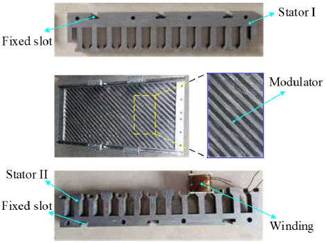
Figure 30: Prototype.
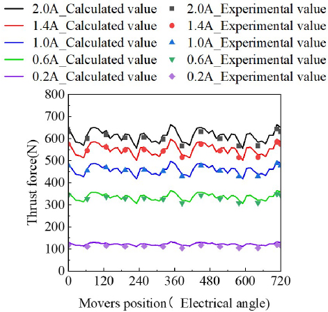
Figure 31: Comparison of prototype test and calculation results.
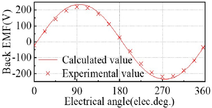
Figure 32: No-load back EMF.
On the other hand, there will be some errors during the motor assembly process. The calculated value of the average thrust and the measured value of the average thrust are compared and analyzed as shown in Table 5. It can be seen that the calculated value and the measured value are highly consistent. The error between the thrust test results and the calculation results is basically within 5%, which meets the engineering error requirements. The no-load back EMF calculation results and measurement results have good consistency as shown in Fig. 32. Therefore, the rationality of the MFM-TFM topology structure proposed in this paper and the accuracy of the calculation results are verified.
Table 5: Prototype thrust simulation and experimental measurement results
| Current (A) | Calculated Thrust Average (N) | Measured Thrust Calculated Value (N) | Error (%) |
| 0.2 | 71.97 | 68.1 | -5.68 |
| 0.6 | 216.94 | 209.38 | -3.61 |
| 1 | 363.21 | 356.18 | -1.97 |
| 1.4 | 490.56 | 483.59 | -1.44 |
| 2 | 612.54 | 605.52 | -1.16 |
V. CONCLUSION
A direct-drive magnetic field modulation transverse flux motor is proposed in this paper. Based on the magnetic field modulation principle, high-speed magnetic field motion can be converted into low-speed high-thrust motion. Based on the transverse magnetic field, stator I and stator II are made of laminated silicon steel. Hysteresis loss, eddy current loss and additional loss are effectively reduced. A prototype is manufactured. An experimental test platform is built. The thrust and back electromotive force are measured and compared with the experimental values. The rationality of the proposed topology and the accuracy of the calculation results are verified. The following conclusions are obtained:
After the action of the tilt modulator, the air gap flux density dominated by the 6th harmonic in the lower air gap is modulated into the air gap flux density dominated by the 5th harmonic in the upper air gap. When the 5-pole magnetic field is generated by the stator I armature winding, the power can be stably transmitted from the stator I armature winding to the mover.
In the modulated air gap flux density, the amplitude of the low-order harmonic is much larger than that of the high-order harmonic. Therefore, the average thrust can be improved by increasing the amplitude of low-order harmonics.
After the air gap width, PM, core and modulator parameters are optimized, the no-load back EMF and current waveform sinusoidal properties are better. Through core lamination, the loss of the transverse flux motor is effectively reduced. The rated average thrust of the motor reaches 612.54 N.
REFERENCES
[1] X. Chai, J. Si, Y. Hu, Y. Li, and D. Wang, “Characteristics analysis of double-sided permanent magnet linear synchronous motor with three-phase toroidal windings,” Applied Computational Electromagnetics Society (ACES) Journal, vol. 36, no. 08, pp. 1099-1107, Oct. 2021.
[2] I. I. Abdalla, T. B. Ibrahim, and N. M. Nor, “A study on different topologies of the tubular linear permanent magnet motor designed for linear reciprocating compressor applications,” Applied Computational Electromagnetics Society (ACES) Journal, vol. 31, no. 01, pp. 85-91, Aug. 2021.
[3] N. Ullah, M. K. Khan, F. Khan, A. Basit, W. Ullah, T. Ahmad, and N. Ahmad, “Comparison of analytical methodologies for analysis of single sided linear permanent magnet flux switching machine: No-load operation,” Applied Computational Electromagnetics Society (ACES) Journal, vol. 33, no. 08, pp. 923-930, July 2021.
[4] M. Jawad, Y. Haitao, Z. Ahmad, and Y. Liu, “Design and analysis of a novel linear oscillating actuator with dual stator rectangular geometry,” Applied Computational Electromagnetics Society (ACES) Journal, vol. 36, no. 10, pp. 1384-1392, Oct. 2021.
[5] X. Deng, R. Li, L. Hao, A. Zhang, and J. Zhou, “Design and finite element analysis of a novel permanent magnet assisted reluctance synchronous motor,” Applied Computational Electromagnetics Society (ACES) Journal, vol. 35, no. 9, pp. 1012-1021, Sep. 2020.
[6] R. Chen, C. He, S. Li, N. Li, L. Zhang, D. Liu, and X. Zhang, “Characterization of partial discharge of metal particles inside gas-insulated switchgear under excitation of disconnecting switch operating overvoltage,” in 2024 7th International Conference on Energy, Electrical and Power Engineering (CEEPE), 2024.
[7] W. Liang and J. Lantao, “Research and development of intelligent control system for motor mechanism of high-voltage circuit breaker,” High Voltage Electrical Appliances, vol. 54, pp. 59-69, Mar. 2018.
[8] C. Fuguo, H. Dawei, Z. Ruimin, and D. Guannan, “Intelligent control system for motor drive of 550 kV high-voltage disconnector,” Instrument Technology and Sensor, pp. 78-82, 87, Apr. 2017.
[9] J. Lipeng, Z. Li, L. Hongliang, D. Chi, L. Kaibao, and J. Dongming, “Finite element numerical calculation of plum blossom contact of high-voltage switch cabinet based on magnetic field-temperature field coupling,” China Testing, vol. 48, pp. 8-12, June 2022.
[10] L. Jianlin, Z. Hongwei, Z. Bin, X. Shaobin, H. Yuhua, L. Tao, and H. Bokai, “Transient temperature rise variation of low-voltage switchgear under short-circuit fault due to electromagnetic thermal coupling,” Journal of Xi’an University of Science and Technology, vol. 41, pp. 1138-1147, June 2021.
[11] M. Xinyou, W. Lijun, W. Rui, and Z. Wenzhe, “Simulation study on temperature rise characteristics of medium voltage switchgear under fault conditions,” High Voltage Technology, vol. 48 pp. 2276-2282, June 2022.
[12] P. Tao, T. Bingnan, Z. Lihua, H. Zhipeng, L. Mingxian, and G. Xiaoxue, “Study on temperature rise characteristics of medium voltage switchgear under typical contact fault,” High Voltage Technology, vol. 47, pp. 4331-4345, Dec. 2021.
[13] L. Jiangtao, S. Yi, and L. Qingyu. “Research on thermal defect assessment algorithm for high current switch cabinet plum blossom contact,” High Voltage Electrical Appliances, vol. 56, pp. 124-129, 138, Nov. 2020.
[14] H. Xinbo, X. Zhipeng, T. Yi, J. Botao, and C. Li, “Thermal fault warning strategy and its application for high voltage switch cabinet,” Electric Power Automation Equipment, vol. 39, pp. 181-187, July 2019.
[15] Z. Wentao, Z. Yiming, W. Zichi, L. Shaohua, and L. Dexiang, “Research on fault diagnosis and analysis method of electromagnet of spring operating mechanism,” High Voltage Electrical Appliances, vol. 56, pp. 209-214, Apr. 2020.
[16] H. Xinbo, W. Haidong, H. Haiyan, Z. Yongcan, Z. Hao, and X. Zhipeng, “Anti-blocking technology and application of electric chassis vehicle for high-voltage switch cabinet,” High Voltage Electrical Appliances, vol. 54, pp. 205-211, 218, Mar. 2018.
[17] L. Jing, M. Jiajian, Z. Dianbo, W. Jing, and C. Kenan, “Simulation analysis and experimental study of temperature field of metal-enclosed high-voltage switchgear trolley contact,” High Voltage Electrical Appliances, vol. 51, pp. 74-79, Aug. 2015.
[18] F. Jiawei, G. Yu, Y. Xingchao, Z. Xiang, and W. Hongwei, “Gear local fault detection using servo motor built-in encoder,” Journal of Vibration Engineering, pp.1-8, June 2024.
[19] C. Ruihong and T. Zhaozhan, “Design of loading and unloading manipulator for gearbox gear meshing test machine,” Machine Tool and Hydraulics, vol. 48, pp. 41-46, Mar. 2020.
[20] S. Rui, L. Pingping, L. Huazhi, H. Yangsen, and W. Jun, “Experimental study on transmission principle of new wind turbine generator set,” Renewable Energy, vol. 36, pp. 1086-1091, July 2018.
[21] L. Jun, K. Baoquan, and Y. Xiaobao, “Optimization and design of double alternating pole transverse flux linear motor,” Transactions of China Electrotechnical Society, vol. 35, pp. 991-1000, May 2020.
[22] B. Q. Kou, J. Luo, X. Yang, and L. Zhang, “Modeling and analysis of a novel transverse-flux flux-reversal linear motor for long-stroke application,” IEEE Trans. Ind. Electron, vol. 63, no. 10, pp. 6238-6248, Oct. 2016.
[23] X. Zhao and S. Niu, “Development of a novel transverse flux tubular linear machine with parallel and complementary PM magnetic circuit for precision industrial processing,” IEEE Trans. Ind. Electron, vol. 66, no. 6, pp. 4945-4955, June 2019.
[24] Z. Yan, J. Si, R. Nie, Z. Cheng, L. Dong, and Z. Li, “Performances analysis of a tubular permanent magnet linear generator with 120 phase belt toroidal windings,” in Proc. 13th Int. Symp. Linear Drives Ind. Appl., 2021.
[25] Z. Yan, J. Si, R. Nie, Z. Cheng, L. Dong, and Z. Li, “Comparative analysis of tubular permanent magnet linear generator with equidirectional toroidal windings and conventional toroidal windings,” IEEE Trans. Ind. Appl., vol. 58, no. 4, pp. 4614-4624, July-Aug. 2022.
BIOGRAPHIES

Yi Su received the master’s degree from Guangxi University, Nanning, China, in 2015. He is currently a senior engineer and researcher. His research interests are motor design, power switchgear design and operation and maintenance technology.

Lei Gao received the B.S. degree from Harbin Institute of Technology, Harbin, China, in 2007. He is currently a senior engineer. His research interests are motor design, power switchgear design and operation and maintenance technology.

Wei Huang received the master’s degree from Guangxi University, Nanning, China, in 2021. He is currently an engineer. His research interests are power switchgear design and operation and maintenance technology.

Jian Qin received the B.S. degree from North China Electric Power University, Beijing, China, in 2000. He is currently a senior engineer. His research interests are power switchgear design and operation and maintenance technology.

Yufeng Lu received the Ph.D. degree from Harbin University of Science and Technology, Harbin, China, in 2013. He is currently a senior engineer and senior researcher. His research interests are power switchgear design and operation and maintenance technology.
ACES JOURNAL, Vol. 40, No. 5, 457–470
doi: 10.13052/2025.ACES.J.400510
© 2025 River Publishers