Design of 3-Bit Angle-insensitive RIS for 5G Communication Systems
T. Islam and A. Eroglu
1North Carolina A&T State University
Greensboro, NC 27411, USA
tislam5@aggies.ncat.edu
2SUNY Polytechnic Institute
Utica, NY 13502, USA
eroglua@sunypoly.edu
Submitted On: September 2, 2024; Accepted On: February 18, 2025
ABSTRACT
This paper introduces a 3-bit reconfigurable intelligent surface (RIS) design characterized by its unique angle-insensitive properties for 5G communication systems. The proposed configuration provides eight distinct phase states enabled by the states of two varactors with an applied bias voltage. The design of the unit cell with double centric square split ring resonators and the formation of the RIS with a 5x5 array have been presented. A detailed analysis of the RIS performance has been conducted using the CST 3D electromagnetic simulator to study the reflection amplitude and phase responses. It is demonstrated that the results show a phase range of up to 315 degrees, along with eight distinct states exhibiting a stable interval of 45 degrees. This effectively covers incidence angles ranging from 0 to 60 degrees.
Index Terms: 3-bit RIS, 5G, angular insensitivity, quantization, reconfigurable intelligent surface, split ring resonator, SRR, varactor.
I. INTRODUCTION
The wireless communication landscape is currently undergoing a transformative phase with the emergence of the reconfigurable intelligent surface (RIS) [1]. These innovative platforms are gaining widespread recognition for their ability to effectively manipulate signal propagation environments, thereby significantly enhancing wireless network performance. The traditional challenges associated with uncontrolled interaction of radio waves environmental elements, which often lead to signal quality deterioration, are being addressed through the deployment of RIS [2]. These surfaces play a pivotal role in optimizing wave reflections, refractions, and scattering, which in turn facilitates the reduction of multipath fading while maintaining low hardware costs and energy efficiency [3–4].
At the core of RIS technology is the metasurface, a crucial component renowned for its remarkable capability to manipulate electromagnetic (EM) waves through meticulously designed and strategically arranged meta-atoms [5]. The concept of digital coding metasurfaces has revolutionized the design process, allowing for real-time programmability and reconfigurability. The integration of tunable components like PIN diodes, varactor diodes, and field-programmable gate arrays (FPGA) has further enhanced the functional diversity of metasurfaces, paving the way for high-performance multifunctional metasurfaces in RIS-assisted wireless communication [6].
This paper introduces a 3-bit programmable RIS to address the challenges arising from angular sensitivity and phase control in RIS. Such sensitivity may lead to issues that can result in the failure of RIS-assisted wireless communication networks such as the ones that rely on the reciprocity of wireless channels [7–8]. The proposed design in this paper features a unit cell which has double centric square split ring resonators (SRRs) with two varactors for phase control, aiming to enhance angular insensitivity [9–10]. The unit cell is then used to form RIS with 55 array configuration. The results demonstrate a phase range of up to 315 degrees, with eight distinct states exhibiting a stable interval of 45 degrees, effectively covering incidence angles from 0 to 60 degrees [11–12].
II. DESIGN OF SRR UNIT CELL
The square SRR unit cell in the design is implemented on a Teflon-based substrate, as depicted in Fig. 1 (a). Each SRR unit cell comprises a square loop with a side length (a) of 5 mm, a split width (d) of 0.5 mm, and a metal width (c) of 0.2 mm, m represents the side length of the SRR unit cell and is equal to 5 mm. The spacing (s) between adjacent SRRs is maintained at 0.5 mm, optimizing the coupling effect and resonance characteristics. A detailed analysis has been conducted and verification using the 3D EM simulator CST. The varactor diode model used is the MAVR-00020-141100 from MACOM. The capacitances of this varactor diode range from 0.75 pF to 2.60 pF.
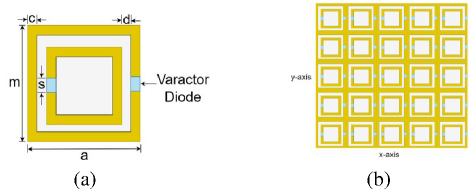
Figure 1: Layout of SRR unit cell with varactor diodes: (a) single element unit cell and (b) 5x5 array with final unit cell.
III. SIMULATION RESULTS AND DISCUSSION
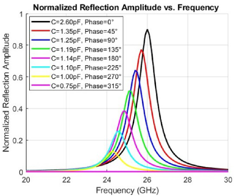
Figure 2: Frequency response of a varactor-tuned RIS.
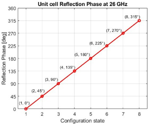
Figure 3: Progressive phase shift characteristics of SRR unit cell at 26 GHz.
Figure 2 illustrates the normalized reflection coefficient amplitude across a frequency range from 20 GHz to 30 GHz for various varactor capacitance values. Each curve represents the response for a specific capacitance value and its corresponding phase shift, demonstrating the shift in the resonant frequency of the element with changes in capacitance. The peak amplitude values in Fig. 2 indicate the resonant points where maximum reflection occurs. These characteristics demonstrate the ability to control the phase of reflected signals by adjusting the varactor capacitance, a key characteristic for beam-steering applications.
Figure 3 displays the linear phase shift progression of a SRR unit cell at 26 GHz, with the reflection phase angle increasing in increments across eight configuration states, ranging from degrees at state 1 to degrees at state 8. In Fig. 4, the variation of the normalized scattering pattern for different incident angles over an degree range is given, with each curve representing the scattering intensity at a specific incident angle.
RIS angular reciprocity is investigated to identify the angular sensitivity of the proposed RIS structure. Sets of simulations have been conducted for the predetermined incident angles and corresponding reflected angles have been measured and illustrated in Table 1.
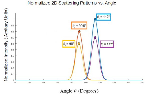
Figure 4: Normalized 2D scattering pattern vs. angle.
| Simulation I | Incident Angle - | 90 | 112.5 |
| Reflected Angle - | 112.5 | 90.5 |
The normalized 2D scattering parameter responses for each incident angle are illustrated in Fig. 4. The simulation results affirm that plane waves are reflected back toward the incidence direction on the RIS, thereby validating the concept of angular reciprocity.
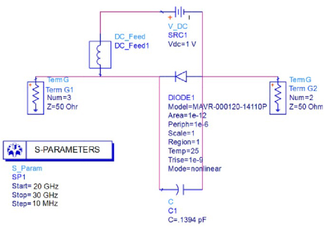
Figure 5: DC biasing circuit for the presented unit cell reconfigurable diode.
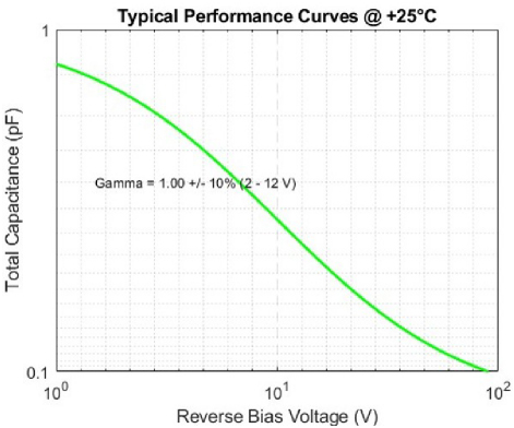
Figure 6: Capacitance of the varactor versus reverse bias voltage.
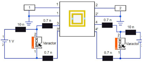
Figure 7: Integrating the SRR unit cell with the DC circuit and SPICE representation for varactor diodes.
The DC biasing circuit for the varactor is given in Fig. 5. Figure 6 gives the capacitance of the varactor versus applied reverse voltage. The complete system with the varactor bias circuit is integrated and simulated as shown in Fig. 7. The return loss for the unit cell when the applied reverse voltage is between 0.5 V and 5.6 V is plotted in Fig. 8. Figure 8 illustrates how the return loss varies with the frequency for each bias setting, indicating the varactor’s performance and tenability within this range.
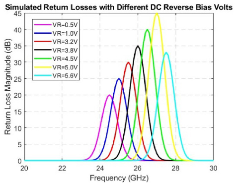
Figure 8: Simulated return losses with different reverse bias voltages.
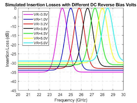
Figure 9: Insertion losses with different reverse biasvoltages.
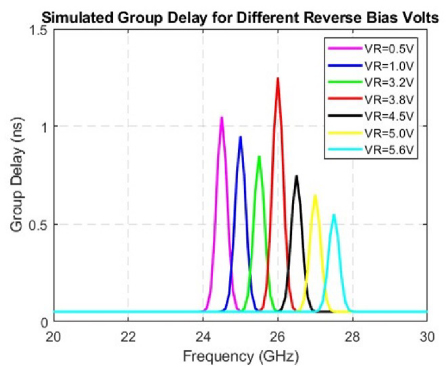
Figure 10: Simulated group delay for different reverse bias voltages.
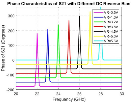
Figure 11: Simulated phase characteristics of S21 with different DC reverse bias voltages.
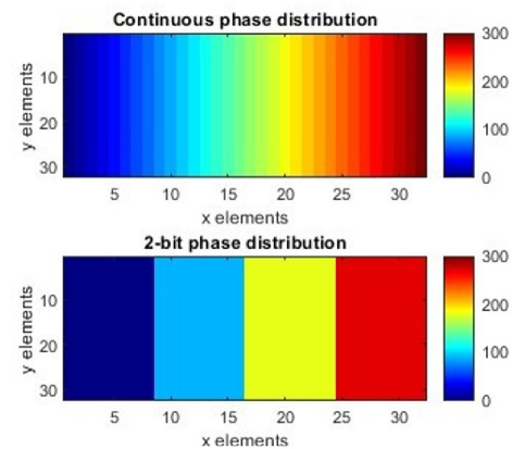
Figure 12: Comparative displays of continuous and 2-bit phase distribution.
Figure 9 illustrates the insertion loss for the applied reverse voltages. Figure 10 gives the group delay for the unit cell when reverse bias voltages vary. The phase characteristics of the insertion loss is given in Fig. 11. Figure 12 shows two color-coded plots representing phase distributions for a RIS. The top plot is labeled “Continuous phase distribution” and shows a gradient of colors, indicating a smooth transition of phase values across the surface. The bottom plot is labeled “2-bit phase distribution” and displays four distinct colors, representing discrete phase states achievable with 2-bit quantization.
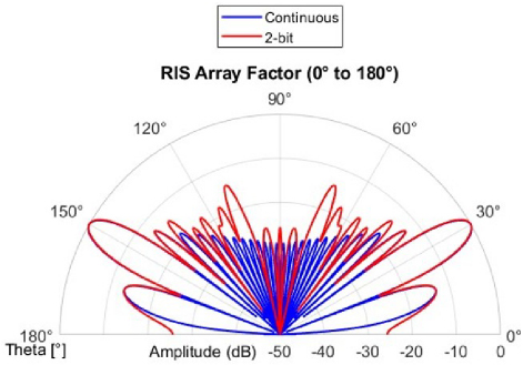
Figure 13: Comparison of continuous and 2-bit phase control for RIS beam steering at 26 GHz.
Figure 13 illustrates the RIS array factor for beam steering, comparing continuous and 2-bit phase control methods. It displays the amplitude in decibels (dB) against the angle theta in degrees. The continuous phase control (blue line) results in a smoother, more precise, steering profile, while the 2-bit phase control (red line) shows a more discretized pattern with higher side lobes, indicating less precise beam control.
Figure 14 displays four plots that compare the performance of an RIS array factor at 26 GHz with the different quantization levels such as 1-bit, 2-bit, and 3-bit. The top left plot indicates the mean quantization phase error which measures the average phase error due to quantization at various reflected angles. The top right plot represents the quantization loss. This plot indicates the power loss associated with phase quantization. The bottom left plot represents the beam pointing error which shows the deviation of the actual beam direction from the intended direction due to quantization. The bottom right plot shows the side lobe level. This plot represents the relative power level of side lobes compared to the main lobe, a critical factor in beamforming performance. Figure 15 contains two graphs depicting the performance of an RIS array at 26 GHz based on the different unit cell sizes (0.1, 0.25, and 0.5 where is the wavelength). The left graph shows the pointing error in degrees as a function of the reflected angle. It demonstrates how the beam’s actual direction deviates from the targeted direction for each unit cell size. The right graph illustrates the level of the side lobes in dB relative to the main lobe, also as a function of the reflected angle, indicating how unit cell size impacts the prominence of the side lobes during beamforming.
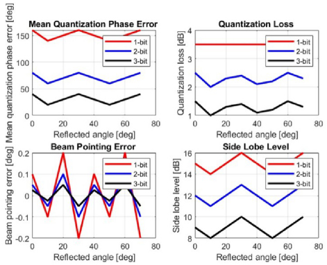
Figure 14: Performance metrics of RIS array factor with phase quantization at 26 GHz.
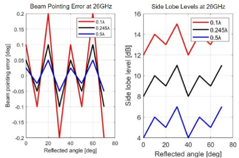
Figure 15: Impact of unit cell size on RIS beam pointing accuracy and side lobe levels at 26 GHz.
IV. CONCLUSION
In this paper, we have designed and simulated a 3-bit reconfigurable intelligent surface (RIS). The proposed design incorporates a unit cell with angular reciprocity, aiming to enhance uplink and downlink misalignment. This improvement addresses the potential risk of failure in RIS-assisted wireless communication networks caused by misalignment issues. It is shown that the RIS presented in this paper achieves a comprehensive phase shift range from to , enabling eight distinct digital states with stable intervals. This has been accomplished by incorporating two varactors and enabling eight distinct phase states by changing the applied voltage. The outcomes of this research can be used for communication systems that rely on precise angular sensitivity and critical phase control.
REFERENCES
[1] Q. Ma, Y. Liu, Z. Zhang, X. Wang, J. Wang, and H. Li, “Smart metasurface with self-adaptively reprogrammable functions,” Light: Science & Applications, vol. 8, no. 1, Oct. 2019.
[2] L. Zhang, X. Q. Chen, S. Liu, Q. Zhang, J. Zhao, and T. J. Cui, “Dynamically realizing arbitrary multi-bit programmable phases using a 2-bit time-domain coding metasurface,” IEEE Transactions on Antennas and Propagation, vol. 68, no. 4, pp. 2984-2992, Apr. 2020.
[3] W. Tang, M. Z. Chen, X. Chen, J. Y. Dai, Y. Han, M. D. Renzo, Y. Zeng, S. Jin, Q. Cheng, and T. J. Cui, “Wireless communications with reconfigurable intelligent surface: Path loss modeling and experimental measurement,” IEEE Transactions on Wireless Communications, vol. 20, no. 1, pp. 421-439, Jan. 2021.
[4] A. Eroglu, RF/Microwave Engineering and Applications in Energy Systems. Hoboken, NJ: Wiley, 2022.
[5] S. Abeywickrama, R. Zhang, Q. Wu, and C. Yuen, “Intelligent reflecting-surface: Practical phase shift model and beamforming optimization,” IEEE Transactions on Communications, vol. 68, no. 9, pp. 5849-5863, Sep. 2020.
[6] M. Di Renzo, A. Zappone, M. Debbah, M.-S. Alouini, C. Yuen, J. D. Rosny, and S. Tretyakov, “Smart radio environments empowered by reconfigurable intelligent surfaces: How it works, state of research, and the road ahead,” IEEE Journal on Selected Areas in Communications, vol. 38, no. 11, pp. 2450-2525, Nov. 2020.
[7] T. S. Rappaport, Y. Xing, O. Kanhere, S. Ju, A. Madanayake, S. Mandal, A. Alkhateeb, and G. C. Trichopoulos, “Wireless communications and applications above 100 GHz: Opportunities and challenges for 6G and beyond,” IEEE Access, vol. 7, pp. 78729-78757, 2019.
[8] L. Dai, B. Wang, M. Wang, X. Yang, J. Tan, S. Bi, and Z. Chen, “Reconfigurable intelligent surface-based wireless communications: Antenna design, prototyping, and experimental results,” IEEE Access, vol. 8, pp. 45913-45923, 2020.
[9] S. R. Biswas, C. E. Gutierrez, A. Nemilentsau, I. H. Lee, S. H. Oh, P. Avouris, and T. Low, “Tunable graphene metasurface reflectarray for cloaking, illusion, and focusing,” Phys. Rev. Appl., vol. 9, no. 034021, 2018.
[10] A. Araghi, M. Khalily, M. Safaei, A. Bagheri, V. Singh, F. Wang, and R. Tafazolli, “Reconfigurable intelligent surface (RIS) in the sub-6 GHz band: Design, implementation, and real-world demonstration,” IEEE Access, vol. 10, pp. 2646-2655, 2022.
[11] A. Pitilakis, O. Tsilipakos, F. Liu, K. M. Kossifos, A. C. Tasolamprou, D. H. Kwon, M. S. Mirmoosa, and C. M. Soukoulis, “A multi-functional reconfigurable metasurface: Electromagnetic design accounting for fabrication aspects,” IEEE Trans. Antennas Propag., vol. 69, no. 3, pp. 1440-1454, 2021.
[12] O. M. Bucci, G. Mazzarella, and G. Panariello, “Reconfigurable arrays by phase-only control,” IEEE Trans. Antennas Propag., vol. 39, no. 7, pp. 919-925, 1991.
BIOGRAPHIES

Tamanna Islam is currently pursuing a Ph.D. in Electrical Engineering at North Carolina A&T State University. She received her M.S. in Electrical Engineering from the same institution in 2023 and her B.S. in Electrical Engineering from the Military Institute of Science and Technology in Bangladesh in 2019. Her professional experience includes work on reconfigurable intelligent surfaces (RIS), phased array antennas, THz sensors, and AI-integrated wireless communication systems. Her research interests include RIS design, THz device development, AI-based beamforming, and adaptive signal processing for 5G and 6G communication systems.

Abdullah Eroglu received his Ph.D. in Electrical Engineering from the Electrical Engineering and Computer Science Department at Syracuse University, Syracuse, NY, USA, in 2004. He was a Senior RF Design Engineer at MKS Instruments from 2000 to 2008, where he was involved in the design of RF systems. He is currently the Dean of the College of Engineering at SUNY Polytechnic Institute and an Emeritus Professor at Purdue University. He was a Faculty Fellow with the Fusion Energy Division at Oak Ridge National Laboratory, Oak Ridge, TN, USA, in 2009. He has published over 170 journal and conference papers and holds five patents. He is the author of six books and co-editor of one book. His current research interests include RF/microwave/THz circuit design and applications, anisotropic, gyrotropic, and metamaterials, RF amplifiers and topologies, antennas, RF metrology, and the wave propagation and radiation characteristics of materials.
ACES JOURNAL, Vol. 40, No. 4, 326–331
doi: 10.13052/2024.ACES.J.400406
© 2025 River Publishers