Wear Analysis of Transmission Gear Tooth of Coal Mining Machine using the Finite Element Method
Shuilin Wang, Fanping Meng, Zhimin Cao, and Zhitao Liang
1Xuhai College, China University of Mining and Technology
Xuzhou, 221008, China
2Institute of Intelligent Manufacturing and Smart Transportation, Suzhou City University
Suzhou, 215104, China
3Henan Energy Group Co. Ltd
Zhengzhou, 450008, China
fpingmeng@163.com, fanping_meng58@outlook.com
Submitted On: September 10, 2024; Accepted On: July 28, 2025
ABSTRACT
This research employs finite element analysis for simulation and calculation to investigate the causes of tooth wear in coal mining machine transmission gears and how it affects gear transmission performance. Utilising Hertz theory, we calculated the maximum contact stress and Hertz half-width during the gear transmission process. A three-dimensional geometric model of the coal mining machine’s right rocker transmission system was created using Pro/E software, which was subsequently analyzed with ANSYS/LS-DYNA for gear meshing. The wear quantity on the gear tooth surface was determined using the Archard wear model, disregarding the effects of lubricant and gear tooth temperature rise. Our simulations revealed the wear distribution and changes in wear amount across various tooth surface wear models under different operating conditions. Notably, we found that wear quantity is directly correlated with tooth wear range and contact stress, with significant wear occurring at the top and root of the tooth. Furthermore, we conducted laser cladding remanufacturing experiments, optimizing process parameters to enhance wear resistance and fatigue strength. The microstructure of the remanufactured tooth face exhibited homogeneity and a lower friction factor than new surfaces. This study offers novel insights into the wear mechanisms of coal mining machine gears. It demonstrates the effectiveness of laser cladding technology in enhancing gear performance, providing practical implications for the design and maintenance of gear systems in harsh operating environments.
Index Terms: Archard wear model, coal mining machine gear transmission, finite element analysis, Hertz contact theory, tooth wear.
I. INTRODUCTION
Gearing is a typical and crucial component of transmission systems, which are essential to the proper operation of coal mining apparatus and equipment [1]. This paper aims to identify the key elements that lead to gear tooth degradation in transmission systems of coal mining machinery and examines how these elements can be assessed quantitatively to improve gear functionality. Utilizing finite element analysis, the study examines the factors contributing to tooth wear, analysing stress distribution and wear patterns across various operational conditions to enhance understanding of the wear mechanisms. The research offers three significant contributions: firstly, it employs advanced finite element modelling to replicate the gear meshing process, yielding important insights into contact stress and wear patterns; secondly, it utilizes Hertz theory to determine the peak contact stress, providing a theoretical basis for grasping gear interactions; and thirdly, it proposes practical suggestions for enhancing gear design and remanufacturing techniques, ultimately seeking to boost the reliability and efficiency of coal mining equipment. The efficiency and safety of coal mining are closely linked to the reliability of the transmission gear, which is the main component of the coal mining equipment. The transmission gears are prone to tooth wear due to the coal mining machine’s complex operating environment and severe force conditions. Understanding Gear tooth wear in coal mining machines is essential for improving efficiency, safety, and cutting maintenance costs. Wear can diminish performance, escalate energy usage, and result in gear failures, which pose safety risks. By identifying the causes of wear, more effective maintenance strategies can be implemented, while advancements in technology improve gear design and durability, ultimately leading to enhanced overall performance. In addition to lowering transmission efficiency, tooth wear can raise noise levels, induce mechanical vibrations, and potentially result in gear failure. The appearance of these issues will significantly increase equipment maintenance costs and cause more downtime, negatively impacting the productivity and financial benefits of coal mining machinery [2]. Thus, researching and analyzing the aspects that contribute to gear tooth wear, as well as its causes, is crucial from a practical standpoint.
In the subject of mechanical transmission, the analysis of gear tooth wear has long been significant. In actual use, contact tension, tooth roughness, material characteristics, and lubrication conditions all work together to cause gear wear [3]. A theoretical foundation for gear design is provided by the Hertz theory-based gear contact stress calculation method, which utilizes the maximum contact stress formula to accurately predict the stress distribution of gears during the meshing process. Hertz theory, however, ignores other intricate considerations such as nonlinear variations in tooth wear and dynamic friction characteristics. As a result, researchers have been progressively developing numerical analytical techniques based on the finite element method in recent years [4]. These techniques enable a more accurate simulation of the stress state and deformation behaviour of gears under various complex operating conditions.
Fatigue fractures in the gearbox housing of a coal mining machine’s cutting part (CPGH) are analyzed by examining external coal cutting and internal gear meshing excitations, using finite element and modal analysis to identify stress concentrations and resonance frequencies. The impact of design parameters on stress is explored to recommend solutions for reducing stress concentration and preventing resonance failures. Finite element analysis predicts tooth root fatigue and Rolling Contact Fatigue (RCF) in spur gears made of steel, titanium, and coated materials. An innovative methodology for loaded tooth contact analysis (LTCA) of spiral bevel gears enhances misalignment predictions, thereby improving gear performance and durability [5-7]. Researching the issue of gear wear is now fraught with difficulties. Firstly, it is challenging to fully and effectively characterize the actual operating conditions of gears using classic analytical approaches due to the extremely nonlinear and time-varying properties of the stress distribution and wear behaviour of gear transmission systems. Second, the accuracy and computational efficiency of the present models are frequently insufficient to account for the multi-scale and multi-physical field coupling difficulties that arise during the gear meshing process, such as contact friction, heat transfer, and material damage [8]. Furthermore, simplified models are frequently utilized in traditional finite element analysis due to limitations in processing power and modelling complexity, which can cause the analysis results to deviate from real working conditions. The credibility of the results may be impacted, for instance, if the lubricant effect and temperature rise are not taken into account. In this scenario, the stress concentration area on the tooth surface determined by the study may differ somewhat from the real wear situation [9, 10]. Similar studies have explored wear in underground construction equipment such as disc cutters in shield tunnelling machines. For instance, one investigation under Baiyun Airport analysed the linear correlation between disc cutter wear and parameters like installation radius, cutting length, and mass-point velocity [11]. The study examined rock behaviour under repeated shield disc cutter impacts, revealing that internal damage accumulates over time, reducing rock strength. Key mechanical responses, including stress and modulus, changed with impact rate, enhancing understanding of the rock-breaking process in tunnelling [12]. In another domain, a fault diagnosis method combining Feature Mode Decomposition (FMD) with Multi-Scale (CNN) Convolutional neural network has been proposed to improve accuracy in helicopter gearbox fault detection. These cross-domain techniques highlight the growing trend of integrating advanced diagnostics and machine learning in wear analysis and machinery fault prediction [13].
Researchers have proposed various changes to address these difficulties. By determining the contact stress and wear range, the wear calculation approach based on Archard’s wear equation is frequently used in gear wear prediction to estimate tooth wear. Archard’s wear model is crucial in studying gear tooth wear, particularly in coal mining machinery, as it provides a theoretical framework for predicting wear rates based on contact mechanics. This model enables a quantitative wear analysis, allowing engineers to design more durable gears by considering material properties, surface treatments, and operating conditions. It also correlates wear with load, sliding distance, and material hardness, thereby aiding in the development of better maintenance strategies and design improvements. The Archard wear equation is:
| (1) |
Where:
V Volume of material worn away (cubic units)
k Wear coefficient (dimensionless)
F Normal load (Newtons)
d Sliding distance (meters or millimetres)
H Hardness of the material (Pascals)
This equation helps to quantify wear and predict gear performance, making it essential for improving design and durability. The nonlinear fluctuation of stress and deformation at each site during gear meshing is not fully taken into account, even though this method makes the wear calculation simpler [14, 15]. The results also depend on the choice of wear coefficients. Furthermore, the numerical simulation method of finite element analysis offers substantial support to the gear wear study. The computation accuracy can be significantly improved by carefully selecting factors such as cell type, mesh density, and material model. It remains a challenging task to address, nevertheless, how to strike a compromise between the model’s correctness and computational efficiency while avoiding instability issues (such as the negative volume phenomenon) throughout the calculation process [16].
In this study, several novel contributions to gear wear analysis are introduced, including the integration of advanced finite element analysis (FEA) with local mesh encryption techniques, improving the accuracy of wear predictions by more precisely evaluating stress concentration areas on gear tooth surfaces. Unlike previous studies that used simplified wear models, this research combines the Archard wear model with detailed simulations to capture the complex interactions between contact stress, nonlinear stress fluctuations, and varying operational conditions. The real-world applications by validating its findings against empirical data from coal mining machinery and enhancing the credibility of the wear predictions are highlighted. Furthermore, it explores the impact of gear wear on remanufacturing processes, particularly through laser cladding, offering new insights into improving wear resistance and fatigue strength. Finally, the research takes a holistic approach, correlating wear with overall gear performance to provide actionable recommendations for strengthening gear design and maintenance strategies. With the aforementioned issues in mind, this research uses the finite element method to conduct a systematic investigation into the wear of the tooth surface of the transmission gears in coal mining machines [17-19]. This paper calculates the contact half-width based on Hertz theory and performs local mesh refinement in the tooth contact region to achieve more precise findings in tooth stress analysis. In addition to improving the accuracy of tooth stress distribution, local encryption can significantly reduce computation time compared to the conventional uniform meshing method [20, 21].
Several tooth wear loss models, including the unworn, full desensitized, and localized wear models, are developed in this paper. These models enable the simulation of the impacts of various wear levels on the gear transmission system’s performance, leading to a more comprehensive understanding of wear behaviour. Gear wear from friction, pressure, and insufficient lubrication lowers efficiency, load capacity, and longevity. Common kinds include tooth flank wear, pitting, and scuffing. As wear progresses, friction, noise, vibration, and temperature rise, potentially leading to failure. Wear rates are influenced by factors such as load, speed, material, and environmental conditions. To minimize the impacts, adequate lubrication, long-lasting materials, an ideal design, and regular maintenance are necessary. Monitoring wear through inspections and analysis extends gear life and ensures system reliability. For the potential negative volume issue that arises throughout the computation procedure, corresponding remedies are also suggested. Computational instability can be efficiently prevented and the reliability of simulation results increased by adjusting the K-file control parameters.In LS-DYNA, the K-file refers to the keyword input file that contains the control parameters required for finite element analysis. This file defines the essential settings for the simulation, including time integration options, contact definitions, material models, and numerical stability controls. By adjusting the K-file parameters, it is possible to mitigate computational instabilities, such as negative volume errors, while also improving the overall accuracy and reliability of the simulation results.
II. HERTZ THEORY-BASED GEAR CONTACT CALCULATION
A. Maximum contact stress calculation in gearing
The maximal contact stress is determined by Hertz theory [22].
| (2) | ||
| (3) |
The degree of overlap of the straight-toothed cylindrical gear transmission is expressed as . The pressure angle is denoted by (∘), while and represent the apex circle pressure angles of the master and slave gears, respectively. The number of teeth of the master and slave gears are denoted by and . The modulus of elasticity of the material is represented by (MPa), and the material’s Poisson’s ratio is . The load factor is indicated as , and the real maximum driving torque of the main wheel is given in Nmm. The transmission ratio is denoted by , the gear tooth width is represented by , and refers to the indexing circle diameter of the main wheel.
B. Hertz half-width
The Hertz contact hypothesis states that for correct analysis results, the mesh at the contact should be drawn more densely. When any point of the gear is involved in meshing, the edge length of the cell at the contact is typically 1/10 of the Hertz half-width or less, meaning that there are more than five contact cells [23]. The equation for Hertz half-width is
| (4) |
III. ANALYSIS OF GEAR MESHING TRANSMISSION USING FINITE ELEMENTS
A. Estimating dental wear
Wear on the tooth surface was calculated using the wear equation developed by Archard [24].
| (5) |
where is the tooth contact stress in is the tooth wear range in is the tooth’s position where the calculation point is in is the total number of wear events that the calculation point has experienced.
During the period, the gear tooth profile experiences a grinding stroke that is proportional to the pressure angles and .
| (6) |
This is derived from the fact that, throughout the gear meshing process, the length of the meshing line remains constant.
| (7) |
The equation involves the following: Here, is the pressure angle at the gear tooth node (°), is the center distance of the gear pair (mm), is the base circle radius of the master and slave gears (mm), and and are the base circle radii of the master and slave gears in mm, respectively.
B. Finite element modeling
Table 1 displays the geometric measurements and material characteristics of the final-stage gears of the easy-to-maintain SL1000 coal mining machine’s right rocker arm drive system.
Table 1: Gear parameters and material properties
| Main and Driven Gears Geometric Parameter | Value 1 | Value 2 | Unit/Note |
| Number of teeth | 27 | 28 | – |
| Modulus | 28 | mm | |
| Pressure angle | 23 | ∘ | |
| Tooth width | 312 | mm | |
| Gear material | 18Cr2Ni4WA | ||
| Elastic modulus | MPa | ||
| Poisson’s ratio µ | 0.288 | ||
| Mass density | kg/mm3 | ||
| Yield limit | MPa |
Pro/E parametric modelling was used to create a three-dimensional geometric model of the gear drive system, taking into account the system’s large size and heavy mass, which resulted in a large number of complete gear model units. The analysis and solution time were excessively long, which had an impact on the solution’s efficiency. The six-tooth active wheel and seven-tooth driven wheel types are established based on the Saint-Venant concept.
After importing the model into ANSYS/LS-DYNA, the Hertz formula was used to determine the Hertz half-width, which was found to be a 4.32 mm. After choosing shell163 four-node tetragonal cells and solid164 eight-node hexahedral cells, the model was subjected to mapping and free-meshing using MESHTOOL [25]. To minimizes computation time and increase the accuracy of the solution, the portion of the mesh that is not involved in meshing can be divided into rough sections. For the meshing of the tooth surface, local mesh refinement is applied to the tooth root stress concentration, with an edge length of 4mm for the cells.
Tooth wear failure frequently occurs in the active wheel at the meshing teeth above the pitch circle, near the tooth top, and in the driven wheel at the meshing teeth below the pitch circle, near the tooth root [26]. This is evident from the coal mining machine rocker arm final-stage gears in the actual working process, as well as from the literature [27, 28].
Based on the Archard wear formula, j 1,000, meaning that only the active wheel characteristics should be considered, as the difference in size between the slave and master gears is not significant. The wear quantity of the tooth at the root is calculated to be 0.0432 mm, and at the top, it is 0.00594 mm. Consequently, the simulation Model 1 shows no wear on the tooth surface; Model 2 shows full damage wear on the active wheel gear tooth surface; and Model 3 shows wear of 0.00594 mm on the active wheel gear tooth surface. Following the split of the finite element model, Figs 1 to 3 show Model 3, which represents the follower wheel gear tooth flank wear of 0.0432 mm among the three typical wheel tooth flank wear loss models.
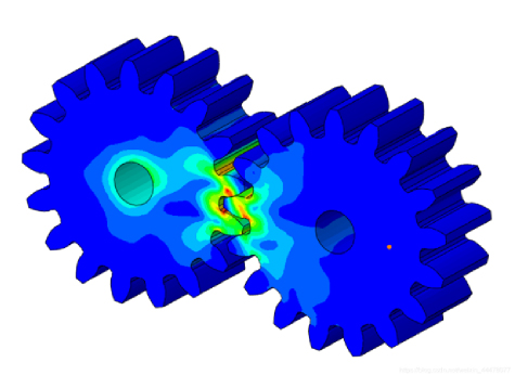
Figure 1: Unworn gear tooth surface (Model 1).
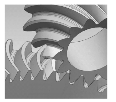
Figure 2: Fully worn gear tooth surface on the active wheel (Model 2).
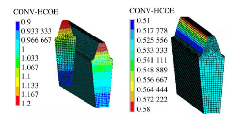
Figure 3: Partially worn follower gear tooth surface with root and top wear (Model 3).
Figure 3 illustrate different simulation results: the left shows the normalized wear depth distribution, while the right shows the corresponding convergence coefficient (CONV-HCOE).
IV. EXPERIMENTATION
A. Preparing worn, remanufactured teeth
There are various procedures involved in preparing worn gear teeth for remanufacturing. First, an initial check evaluates the wear and damage to the gear. Sandblasting is then used to clean the gear’s surface, eliminating pollutants and preparing it for subsequent treatment. Following that, cracks are identified using procedures such as optical inspection, liquid penetrant testing, magnetic particle testing, and ultrasonography. Once cracks and faults are discovered, a thorough inspection decides whether the gear can be fixed or replaced. If the gear is repairable, it undergoes additional preparation, such as removing fatigue layers and applying surface treatments to restore its functionality. Throughout the process, documentation is kept to chronicle discoveries and actions performed. The working surface hardness of the gear teeth on the low-speed, heavy-duty walking track gear steel grade 18Cr2Ni4WA was measured to be between HRC58.6 and 61.5, with a tooth core measuring HRC38.2. To simplify the experimental process and provide 48 mm, or half of the tooth width, for the study, a wire cutter will be used to cut out the block, depicted in Fig. 4, along the root of the wheel teeth. Figure 4 (a) depicts the pitting area following sandblasting to identify the fatigue pitting area, whereas Fig. 4 (b) shows the end face broken tooth drop block. The fatigue pitting region in Fig. 4 (a) is dispersed over the upper half of the tooth height and is wider in the vicinity of the tooth’s end face. The upper portion of the tooth height and the top of the tooth are where the majority of the broken teeth are located in the Fig. 4 (b). The distribution of the fatigue region location was clarified after sandblasting, oil removal, and rust treatment. Slag removal and fault identification are necessary before laser cladding; otherwise, the slag and the original residual fractures will constitute the cause of cracks in the cladding layer.
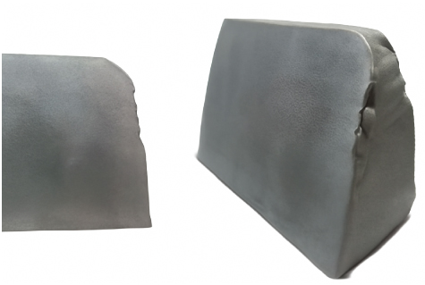
Figure 4: Gear teeth following sandblasting: (a) Prolonged tensile deformation area; (b) Oblique tensile deformation area
In our study, we utilized a belt sander to “sand-blast” the gear tooth work surface multiple times until the pitting craters are entirely gone to remove the fatigue pitting layer. The gear tooth’s working face was then liquid probed and kept sanded to check for any cracks. The thickness of the unilateral gear tooth’s working face was measured to have decreased by 0.25 mm following the removal of the fatigue layer and the discovery of cracks.
B. Laser remanufacturing of tooth flanks
The powdered nickel-based fusion alloy and blended Ni60A: CeO2 99:1 (mass ratio) were ball-milled for 8 hours at a rotational speed of 650 r/min. The powder was then dried in a vacuum drying furnace at 150 °C for 1.5 hours to completely dehumidify it and prevent the formation of air holes caused by the failure of water vapour to be discharged from the metal during the fusion cladding process, due to the metal’s high-speed solidification, as shown in Table 2.
Table 2: Parameters of the laser cladding method
| Variable Parameters | Numerical Value |
| Power kW | 3.3 |
| Spot size | |
| Spot velocity | 9 |
| Rate of powder delivery | 4.8 |
| Rate of overlap between neighboring fusion trajectories | 42 |
| Powder that contains gas | Ar |
| Coaxial shielding flow rate of argon gas | 590 |
Figure 5 displays the working surface morphology of the gear teeth following laser cladding.
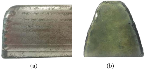
Figure 5: Functional shape of wheel teeth after cladding: (a) Gear working surface; (b) Gear tooth end showing the start and end of laser cladding.
After welding, the rectangular laser spot has a surface that is nearly smooth and clean, similar to net moulding, as seen in Fig. 6. The rectangular spot has two major advantages over the circular spot, in addition to surface finishing: firstly, the surface interaction with the substrate is smooth; secondly, as illustrated in Fig. 6, the melting efficiency is high.
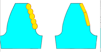
Figure 6: Fused cladding bonding interface schematic diagram: (a) Circular polishing; (b) Short polishing.
Abrupt changes in stress at the bonding interface are easily produced because the cladding layer’s material properties, such as Poisson’s ratio and modulus of elasticity, differ from the substrate’s. Interestingly, Laves phase, a brittle material at ambient temperature, is the material present at the bonding interface. Due to the Laves phase’s brittleness, it is best to reduce both its content and overall area, as a large amount of Laves phase will weaken the mechanical qualities of the tooth surface.
C. Microstructure near the overlap zone’s interface
As seen in Fig. 7, the upper surface of the matching coating is smooth, clean, and neat. The interface between the lower portion of the fused cladding layer and the substrate at the adjacent two laser laps is reasonably flat, with nearly no fluctuation or undulation. A “reasonably flat” interface between the cladding layer and the substrate in laser remanufactured coatings is essential for gear teeth’ mechanical integrity and performance, especially in demanding environments like coal mining machinery. A flat interface promotes even load distribution, reducing localised stress concentrations that can cause premature failures such as fatigue, cracking, and spalling, thereby enhancing gear durability and longevity. The rapid geometry changes lead to high-stress points, increasing the risk of wear and failure. Improved bonding between the cladding and substrate is facilitated by a flat interface, which prevents delamination and ensures efficient load transfer. The wear resistance of the cladding layer benefits from a flat surface, which allows uniform material distribution and mitigates rapid wear. Additionally, a flat interface aids in thermal management by enhancing heat dissipation, thereby preventing localizeds overheating that could degrade material properties. From a microstructural perspective, a flat interface promotes a consistent microstructure, which is essential for achieving the desired hardness and toughness, thereby reducing wear inconsistencies. Overall, sustaining a ”reasonably flat” interface is crucial for gear systems’ longevity, wear resistance, and reliability, enhancing bonding quality and thermal management while minimising stress concentrations. The laser remanufactured fused cladding layer is free of defects such as pores, fissures, and unfused particles, and it is uniformly and densely organised.
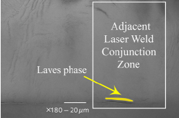
Figure 7: Microstructure of the adjacent laser weld conjunction zone showing the presence of the Laves phase (magnification: ×180, scale: 20 µm).
Compared to the wavy binding interface of a circular spot, the gentle binding interface of a rectangular spot has a smaller Laves phase area.
D. Laser-remanufactured composite coatings’ wear properties
Samples of wear performance are taken from the new gear block at the same location as the rectangular laser-coated tooth face block. It can be conclusively demonstrated that the process parameters used for manufacturing laser wear-resistant coatings are successful if the fatigue zone is chosen as the wear test location and its test performance surpasses that of the new gear tooth surface.
The rectangular area in Fig. 9 (a) of 10 20 mm2 and 10 mm in height along the tooth surface downward was selected as the wear surface to be examined. The tooth surface was then smoothed with sandpaper and polished with a polishing machine to a surface roughness of 0. 2 µm.
A UMT-2 friction and wear testing machine was used to conduct the experiments. The following were the working conditions: room temperature of 23 °C, loaded with 25 N, reciprocating discs in dry wear mode without lubrication, single test duration of 7,200 s, grinding ball diameter of 5.6 mm, GCr15 steel ball material, and 5 mm abrasion mark length.
It is evident from the comparison of Figs. 8 (a) and 8 (b) that the newly created tooth flanks perform significantly worse than the laser-prepared remanufactured wear-resistant coatings. Following an identical wear performance test, the laser cladding surface exhibits nearly no wear markings at all. In contrast, the wear pattern of the fresh flank samples displays larger wear grooves in the middle. In Figs. 8 (c) and 8 (d), the laser nickel-based coating and the new tooth face grinding GCr15 beads on the wear surface demonstrate a relatively flat and smooth wear morphology, when compared to the grinding of the GCr15 beads. Meanwhile, the new tooth face cutting block, when subjected to the grinding of the GCr15 beads from both sides of the gradual protrusion, clearly displays a micro-ploughing morphology.
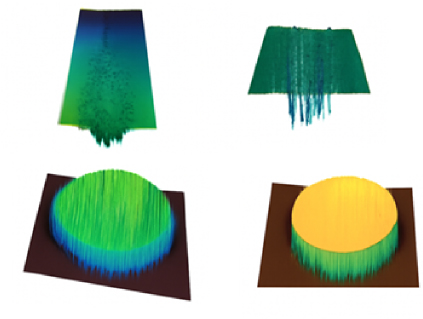
Figure 8: 3D topographical surface plots of gear tooth surfaces after the abrasion test: (a) Least recently structured containment coating; (b) New producer tooth sonic sites; (c) Surface height variation up to 83 µm; (d) Surface height variation up to 40 µm.
E. Curve of the friction factor
The friction factor curve is a valuable tool for evaluating the performance of laser-remanufactured coatings compared to new tooth surfaces, particularly in gear systems. It measures the resistance to motion between two surfaces, taking into account surface roughness, material properties, and lubrication. The curve shows higher friction during the initial running-in phase, followed by a stable wear stage. By analyzing this curve, it is evident that laser-remanufactured coatings offer superior wear resistance, improved lubrication, and lower energy losses compared to new tooth surfaces, which tend to degrade more quickly. This makes remanufactured coatings more efficient and durable, making them ideal for applications that require long-term performance and lower operating costs. The curve also provides valuable insights for predictive maintenance, process optimisations, and material selection, helping reduce energy consumption, improve efficiency, and prevent unexpected failures. In summary, the friction factor curve is a crucial tool for evaluating the effectiveness of laser-remanufactured coatings in terms of wear resistance, efficiency, and gear performance. The friction factor of the laser remanufactured coating is consistently lower than the friction factor of the new tooth surface after the running-in process ends and the tooth surface enters the stable wear stage, as shown by the comparison between the two in Fig. 9. Additionally, the difference tends to continue growing.
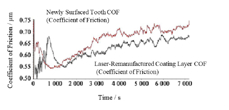
Figure 9: Friction factor between a newly surfaced tooth and a laser-remanufactured coating.
Furthermore, there is a close relationship between wear performance and fatigue performance, as they are essentially the macroscopic expressions of the build-up of microcrystalline dislocations at the metal microcrystalline boundaries of the tooth surface, which eventually cause slippage and spalling. The finer grains in the fine and compact fine-grain reinforced wear-resistant coatings made possible by the addition of rare earths mean that, in theory, their fatigue performance will be higher than that of the tooth surface with coarser grains.
V. CONCLUSION
This study uses Hertz theory and finite element analysis to examine gear tooth surface wear in coal mining machinery, focusing on stress concentration at the tooth’s crown and roots. Laser cladding remanufacturing develops wear resistance and fatigue strength. Still, the Archard wear model determines that tooth wear is directly related to sliding distance and contact stress, with wear increasing dramatically at the crown and root. This study enhances the gear wear mechanisms in coal mining machinery by providing empirical data on the performance of laser-remanufactured coatings compared to new tooth surfaces. The findings provide critical insights into optimizing gear design and remanufacturing processes, resulting in increased operational efficiency and reduced maintenance costs. The study’s novelty is combining finite element analysis with experimental wear testing to estimate laser cladding performance. It helps innovation in gear material selection and surface treatments by correlating microstructural properties to wear behavior. Likewise, applying friction factor analysis as a predictive technique represents a big step forward in assessing gear systems under various operational conditions.
Declarations
Funding: This research was supported by the “Qinglan Project” of colleges and universities in Jiangsu Province, Grant Number: 2022.
Conflicts of interests: The authors declare no conflict of interest.
Data Availability Statement: No datasets were generated or analyzed during the current study.
Code availability: Not Applicable.
Authors’ Contributions: Shuilin Wang, Zhimin Cao, Zhitao Liang: Responsible for designing the framework, analyzing the performance, validating the results, and writing the article. Fanping Meng: Responsible for collecting information, providing software, conducting a critical review, administering the process, and serving as the corresponding author.
REFERENCES
[1] X. Zhao, W. Fan, Z. Wang, Z. Wen, and P. Wang, “An explicit finite element approach for simulations of transient meshing contact of gear pairs and the resulting wear,” Wear, vol. 523, Art. no. 204802, June 2023.
[2] A. G. Mustafayev and C. R. Nasirov, “A study of factors affecting wear and destruction of teeth in gear mechanisms,” Nafta-Gaz, vol. 79, no. 9, pp. 604–610, Sept. 2023.
[3] J. Alam and S. Panda, “Multi-objective optimization with finite element analysis of profile shifted altered tooth sum spur gear,” Advances in Materials and Processing Technologies, vol. 10, no. 2, pp. 1024–1051, Jan. 2024.
[4] Y. Yang, N. Hu, Y. Li, Z. Cheng, and G. Shen, “Dynamic modelling and analysis of planetary gear system for tooth fault diagnosis,” Mechanical Systems and Signal Processing, vol. 207, p. 110946, Jan. 2024.
[5] R. Zhang, Y. Zhang, L. Zhu, and J. Huang, “Fatigue failure mechanism of coal mining machine cutting gearbox housing,” Journal of the Brazilian Society of Mechanical Sciences and Engineering, vol. 42, pp. 1–15, May 2020.
[6] S. Baragetti, “Finite element analysis and experiments for predicting fatigue and rolling contact fatigue behavior of spur gears,” Periodica Polytechnica Mechanical Engineering, vol. 66, no. 4, pp. 304–313, Oct. 2022.
[7] Y. Liu, “A semi-analytical loaded contact model and load tooth contact analysis approach of ease-off spiral bevel gears,” Machines, vol. 12, no. 9, p. 623, Sept. 2024.
[8] A. Czakó, K. Řehák, A. Prokop, J. Rekem, D. Lástic, and M. Trochta, “Static transmission error measurement of various gear-shaft systems by finite element analysis,” Journal of Measurements in Engineering, vol. 12, no. 1, pp. 183–198, Dec. 2024.
[9] S. Mo, L. Wang, Q. Hu, G. Cen, and Y. Huang, “Coupling failure dynamics of tooth surface morphology and wear based on fractal theory,” Nonlinear Dynamics, vol. 112, no. 1, pp. 175–195, Nov. 2024.
[10] M. Li, Y. Luo, L. Xie, C. Tong, and C. Chen, “Fatigue reliability assessment method for wind power gear system based on multidimensional finite element method,” Proceedings of the Institution of Mechanical Engineers, Part O: Journal of Risk and Reliability, vol. 238, no. 3, pp. 540–558, Apr. 2024.
[11] B. Zou, Y. Chen, Y. Bao, Z. Liu, B. Hu, J. Ma, and X. Long, “Impact of tunneling parameters on disc cutter wear during rock breaking in transient conditions,” Wear, vols. 560–561, Art. no. 205620, 2025.
[12] B. Zou, J. Yin, Z. Liu, and X. Long, “Transient rock breaking characteristics by successive impact of shield disc cutters under confining pressure conditions,” Tunnelling and Underground Space Technology, vol. 150, Art. no. 105861, 2024.
[13] A. Wan, Z. Zhu, K. Al-Bukhaiti, X. Cheng, X. Ji, J. Wang, and T. Shan, “Fault diagnosis of helicopter accessory gearbox under multiple operating conditions based on feature mode decomposition and multi-scale convolutional neural networks,” Applied Soft Computing, vol. 180, Art. no. 113403, 2025.
[14] D. Wu, C. Zhang, H. Wu, L. Ji, R. Ran, and Y. Xu, “Forest fire recognition based on feature extraction from multi-view images,” Traitement du Signal, vol. 38, no. 3, pp. 775–783, June 2021.
[15] F. Andary, C. Heinzel, S. Wischmann, J. Berroth, and G. Jacobs, “Calculation of tooth pair stiffness by finite element analysis for the multibody simulation of flexible gear pairs with helical teeth and flank modifications,” Multibody System Dynamics, vol. 59, no. 4, pp. 395–428, July 2023.
[16] Z. Ali, W. Imdad, Q. B. Jamali, I. A. Memo, F. A. Solangi, and S. Ahmed, “Tooth strength analysis of bevel gear using SolidWorks simulation tool,” Journal of Computing & Biomedical Informatics, vol. 6, no. 1, pp. 230–237, Dec. 2023.
[17] Y. Wu, “Exploration of the integration and application of the modern new Chinese style interior design,” International Journal for Housing Science and its Applications, vol. 45, no. 2, pp. 28–36, June 2024.
[18] W. Wang, “ESG performance on the financing cost of A-share listed companies and an empirical study,” International Journal for Housing Science and its Applications, vol. 45, no. 2, pp. 1–7, June 2024.
[19] B. Pang, X. Wang, and T. Zhang, “Reliability analysis of thin-walled ring gear based on tooth surface fatigue and wear,” Journal of Mechanical Science and Technology, vol. 38, no. 4, pp. 1985–1997, Apr. 2024.
[20] P. Sreekar, “Cost-effective cloud-based big data mining with K-means clustering: An analysis of Gaussian data,” International Journal of Engineering & Science Research, vol. 10, no. 1, pp. 229–249, May 2020.
[21] N. S. Allur, “Big data-driven agricultural supply chain management: Trustworthy scheduling optimization with DSS and MILP techniques,” IEEE Access, vol. 8, no. 4, pp. 1–16, Aug. 2020.
[22] S. Mo, L. Wang, M. Liu, Q. Hu, H. Bao, G. Cen, and Y. Huang, “Study of the time-varying mesh stiffness of two-stage planetary gear train considering tooth surface wear,” Proceedings of the Institution of Mechanical Engineers, Part C: Journal of Mechanical Engineering Science, vol. 238, no. 1, pp. 279–297, Apr. 2024.
[23] Y. Guan, J. Wang, Q. Wang, K. Ning, and B. Wang, “Three-arc gear coupling design analysis for high load-carrying applications,” Proceedings of the Institution of Mechanical Engineers, Part C: Journal of Mechanical Engineering Science, vol. 237, no. 24, pp. 5853–5864, 2023.
[24] C. Jia, G. Zhang, and G. Li, “Numerical analysis of tooth contact and wear characteristics of internal cylindrical gears with curved meshing line,” Applied Sciences, vol. 14, no. 13, p. 5399,2024.
[25] Z. Zhao, Y. Yang, H. Ma, H. Wang, H. Tian, and C. Han, “Meshing characteristics of spur gear pairs with tooth modification under different assembly errors and sensitivity analysis for impact factors,” Journal of Mechanical Science and Technology, vol. 37, no. 1, pp. 149–162, Dec.2023.
[26] L. Guo and Y. Sun, “Economic forecasting analysis of high-dimensional multifractal action based on financial time series,” International Journal for Housing Science and its Applications, vol. 45, no. 1, pp. 11–19, 2024.
[27] K. Saqib, “Postmodernism, social dynamics, and e-commerce evolution,” International Journal for Housing Science and its Applications, vol. 45, no. 1, pp. 20–24, 2024.
[28] I. M. Jamadar, R. Nithin, S. Nagashree, V. P. Prasad, M. Preetham, P. K. Samal, and S. Singh, “Spur gear fault detection using design of experiments and support vector machine (SVM) algorithm,” Journal of Failure Analysis and Prevention, vol. 23, no. 5, pp. 2014–2028, Aug.2023.
BIOGRAPHIES

Shuilin Wang (born September 1983) is a female scholar of Han nationality from Bayannur, Inner Mongolia. She holds a Ph.D. and is an Associate Professor at Xuhai College, China University of Mining and Technology. Her main research interests include mining machinery design, fault diagnosis, and analysis.

Fanping Meng (born March 1981) is a male scholar of Han nationality from Weifang, Shandong Province. He holds a Master’s degree and currently works in the Human Resources Department of Henan Energy Group Co., Ltd. His primary research focus is on the management of mining machinery and equipment.

Zhimin Caomale, holds a Master’s degree and is affiliated with the Institute of Intelligent Manufacturing and Smart Transportation, Suzhou City University, Suzhou, China. His research focuses on the design and application of mining machinery as well as intelligent manufacturing technologies.

Zhitao Liang male, is affiliated with the Institute of Intelligent Manufacturing and Smart Transportation, Suzhou City University, Suzhou, China. His main research interests include mining machinery design, mechanical fault diagnosis, and intelligent manufacturing systems.
ACES JOURNAL, Vol. 40, No. 8, 778–787
doi: 10.13052/2024.ACES.J.400810
© 2025 River Publishers