A Novel Multi-objective Synthesis Method of Non-uniform Excitation Sparse Square Planar Transmitting Array Antenna for Microwave Wireless Power Transmission
Jianxiong Li, Ranran Zhang, and Ziyu Han
1School of Electronic and Information Engineering
Tiangong University, Tianjin 300387, China
lijianxiong@tiangong.edu.cn, zhangranran202203@163.com
2School of Electronic Science and Engineering
National University of Defense Technology, Changsha 410000, China
hanziyu23h_@nudt.edu.cn
Submitted On: September 19, 2024; Accepted On: November 11, 2024
ABSTRACT
A novel multi-objective optimal subarray partitioning synthesis method for non-uniformly excited sparse square planar array (NESSPA) antenna is proposed for the problems of maximizing beam collection efficiency (BCE) and minimizing excitation difference (diff) in microwave wireless power transmission (MWPT). The algorithm adopts the multi-objective particle swarm optimization algorithm based on the set of non-dominated solutions (NDSMOPSO) proposed in this paper, which determines the non-dominated solutions in the swarm according to the fitness value and updates the population during the evolution process; the array element positions and excitations are optimized simultaneously in each iteration. In addition, the performance parameter diff proposed in this paper can effectively measure the performance of the array; in general, the smaller the diff, the better the array performance. The effectiveness of the algorithm is demonstrated through a large number of simulations and, according to the method proposed in this paper compared with other two-step methods, a higher BCE can be obtained with fewer subarrays.
Index Terms: Beam collection efficiency (BCE), microwave wireless power transmission (MWPT), multi-objective particle swarm optimization algorithm based on the set of non-dominated solutions (NDSMOPSO), subarray partitioning.
I. INTRODUCTION
Microwave radio energy transmission is a technology that utilizes microwave devices to convert electrical energy into electromagnetic energy, wirelessly transmits microwave electromagnetic energy in space through a transmitting antenna, and converts the electromagnetic energy into electrical energy, which is rectified, filtered, and other transformations, and then supplied to the electrical load [1]. This is an extensively studied technology for long-distance energy transmission [2], and is widely used in various fields such as space solar power stations [3], large phased arrays [4], space transmission [5], and unmanned aerial vehicles [6–7].The microwave radio energy transmission system has two important components: the transmitting antenna and the rectifying antenna. The transmitting antenna is designed to form an enhanced microwave beam towards a given area while minimizing the radiated power outside the collection area. Improving the beam collection efficiency (BCE) in microwave wireless power transmission (MWPT) systems has been a hot research topic in recent years[8–11]. In order to maximize the BCE to improve the performance of MWPT systems [12–14] transformed the solution formula of BCE into a generalized eigenvalue equation, through which the theoretical maximum BCE and the optimal excitation are calculated. However, the emergence of quasi-Gaussian characteristics of the optimal excitation indicates that each element needs to be equipped with a separate amplifier and phase shifter, and thus the system becomes large, complex, and expensive. In order to reduce the cost, scholars began to study sparse arrays [15–17]. Sparse arrays can reduce the cost to some extent, but designing amplifiers for each array element is still complicated due to the use of non-uniform excitation. Although the cost can be greatly reduced by using uniform excitation, the BCE is reduced too much. In order to maintain a high BCE and further reduce the cost, scholars have started to apply subarray division techniques to sparse arrays [16–22]. Scholars usually divide the process of subarray division into two steps. The first step is to optimize the positions of the elements, and the second step is to optimize the excitations of the elements [19], or to perform the subarray division first and then optimize the positions of the elements [16]. The results obtained from these two-step approaches are usually not optimal. When the second step is completed, perhaps the suboptimal becomes the best. In addition, research on multi-objective optimization mainly focuses on beam direction map synthesis of antenna arrays [23–24]. BCE is closely related to several key indexes in beam direction map synthesis, such as sidelobe level outside the receiving area, the main flap beamwidth, and the directionality.
Aiming at the above problems, this paper proposes an optimization algorithm that combines population updating during the evolution with a multi-objective one-step method. The main innovations of this paper are as follows. The first point is that by using the multi-objective particle swarm optimization algorithm based on non-dominated solutions (NDSMOPSO) introduced in this paper, the proposed method is a one-step optimization algorithm that optimizes both the position of the array element and the excitation in the process of population updating with evolution, and the two indexes of maximizing the BCE and minimizing the excitation difference (diff) are selected as the optimization objectives. This one-step algorithm combined with the population update is more effective than two-step algorithms. The second point is that the non-uniformly excited sparse square planar array (NESSPA) model has high optimization degrees of freedom and has the potential to give better results. The last point is that the performance parameter diff is proposed in this paper to measure the performance of subarray division. The effectiveness of the method can be demonstrated by several numerical simulations.
The framework of this paper is as follows. Section II describes the derivation of formulas for subarray division. Section III describes the procedure of the NDSMOPSO method and its application to NESSPA synthesis. Section IV reports the numerical simulation results. Section V offers some conclusions.
II. NESSPA MODEL AND THE FORMULA DERIVATION FOR SUBARRAY PARTITION
The geometric model of the NESSPA MWPT system is shown in Fig. 1. Assume that the aperture of the transmitting array is , and the total number of array elements is . The array elements are distributed in the XOY plane and the coordinate of the nth array element is ,. The position coordinates of some elements are listed in Fig. 1. We use and to denote the square receiving area and the circular receiving area, respectively.
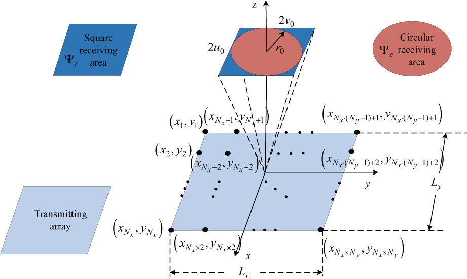
Figure 1: Geometric model of the NESSPA MWPT system.
The array factor of NESSPA could be written as [14]:
| (1) |
where , , and denote the wavenumber, wavelength, and excitation, respectively. and denote the angular coordinates. BCE is defined as the proportion of the power collected by the receiving array to the total power generated from the transmitting array, which could be expressed as:
| (2) |
where represents the power radiating through the area , , and . and are regions of angular coordinates that identify the radiating area and entire visible range. BCE can be rewritten as [14]:
| (3) |
where I, A and B can be expressed as:
| (4) |
where:
| (5) |
Sidelobe level outside (CSL) is defined as the highest normalized sidelobe level outside the receiving area [14], which could be expressed as:
| (6) |
Suppose N elements are divided into M subarrays. SR denotes the subarray layout matrix, which is a matrix as follows:
To satisfy the condition that each array element belongs to only one subarray, the following expression is required:
| (8) |
Assume denotes the subarray excitation vector. represents the boundary of M subarrays. Thus, the calculation method can be expressed as:
| (9) |
where and represent the minimum and the maximum of I, respectively. Then, SR can be obtained in the following way:
| (10) |
The excitation of each subarray can be calculated as:
| (11) |
The excitation vector after partitioning the subarray named as can be obtained by:
| (12) |
The between and can be defined as (13), which can be used as a performance indicator:
| (13) |
III. THE NDSMOPSO METHOD AND ITS APPLICATION FOR SYNTHESIS OF NESSPA
In this section, we will introduce the NESSPA model and the one-step method. By using the one-step method the mathematical model of NESSPA could be expressed as:
| (14) |
Below is a step-by-step procedure description of the one-step method that uses NDSMOPSO. The meanings of some parameters involved are shown in Table 1.
Table 1: Definition of the parameters
| Parameter | Definition |
| NP | number of particles in the population |
| T | maximum number of iterations |
| t | current number of iterations; the variable with subscript t denotes the value of the tth iteration |
| learning factors | |
| w | weight coefficient |
| updated velocity of the tth iteration | |
| minimum array element spacing |
In addition, and are the global optima of BCE and diff, respectively, and are the global optimal positions of BCE and diff, respectively.
After the above steps, the minimum diff and the maximum BCE can be obtained. The innovation of this article is that the proposed integrated optimization method is a combination of population with evolution update and one-step method. What’s more, we improved the weight and step size and used multiple learning factors to achieve multi-objective optimization.
IV. NUMERICAL ANALYSIS
In this part, the validity of the presented algorithm in handling different receiving areas (square and circle) would be tested from two aspects. Firstly, we use the presented algorithm to optimize the NESSPA model under different sparsity of M and N. Secondly, to prove the behavior of the algorithm and the model introduced in this article, we use some performance parameters to compare the NESSPA model with another four planar array models. The simulation software used in all simulations is MATLAB R2022b.
We use four performance indicators to evaluate the comparison of comprehensive results. They are BCE, CSL, , and . and represent amplifier sparsity and element sparsity, respectively, where denotes the maximum number of array elements that can be accommodated by the array under the condition of . In our simulations, T is set to 100 and NP is set to 100. , , and are set to 0.2. and are set to 2. and are set to 0.9 and 0.4, respectively. is set to 1. is set to .
A. Synthesis results of the NESSPA model by using NDSMOPSO under different and
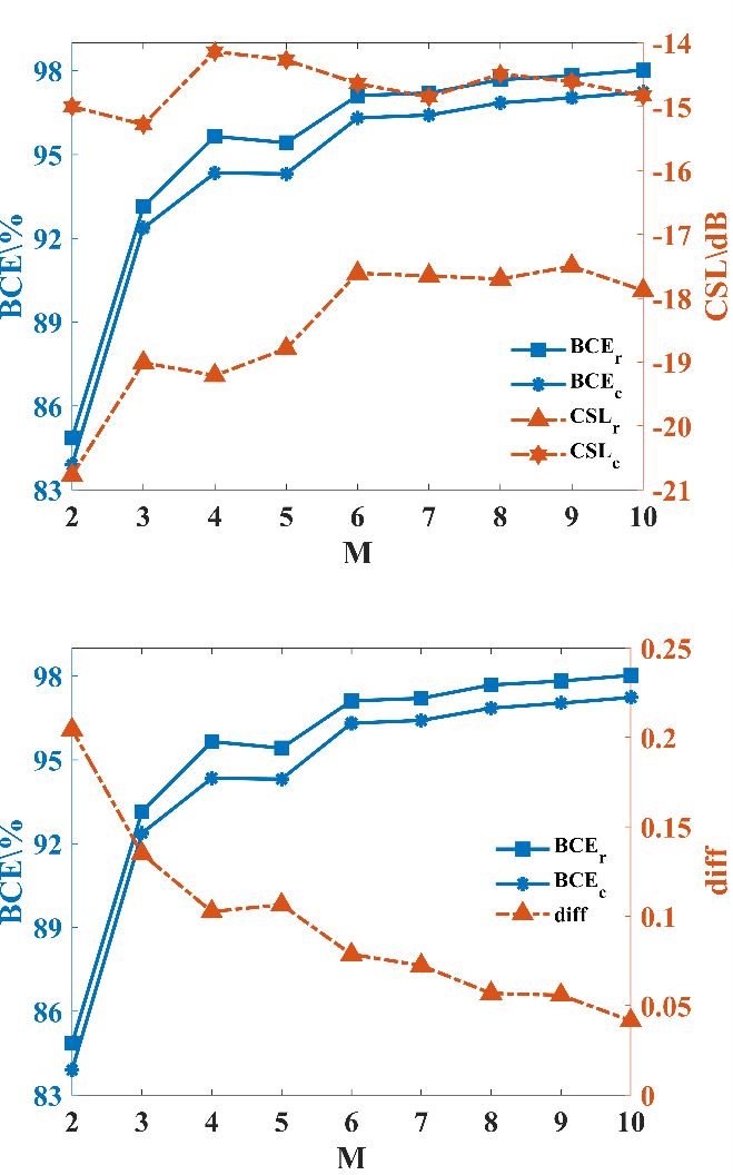
Figure 2: Results of NESSPA under different M at : (a) BCE and CSL and (b) BCE and diff.
Table 2: Numerical results of NESSPA under different BCE (%) and CSL (dB)
| M | BCE | BCE | CSL | CSL | diff |
| 2 | 84.85 | 83.90 | -20.77 | -15.00 | 0.2044 |
| 3 | 93.14 | 92.37 | -19.01 | -15.28 | 0.1350 |
| 4 | 95.65 | 94.34 | -19.20 | -14.14 | 0.1026 |
| 5 | 95.42 | 94.31 | -18.79 | -14.27 | 0.1065 |
| 6 | 97.11 | 96.31 | -17.61 | -14.64 | 0.0787 |
| 7 | 97.20 | 96.41 | -17.65 | -14.85 | 0.0725 |
| 8 | 97.68 | 96.85 | -17.70 | -14.49 | 0.0569 |
| 9 | 97.82 | 97.03 | -17.50 | -14.61 | 0.0559 |
| 10 | 98.02 | 97.23 | -17.88 | -14.83 | 0.0416 |
The first set of simulation in this section involves synthesis of NESSPA with elements. is set to . We performed tests on the influence of different M on the behavior of the array. The synthesis findings are displayed in Fig. 2 and Table 2 (, represent the value under the rectangular receiving area, and , represent the value under the circular receiving area). At , the BCE values in the rectangular and circular regions increase significantly, by about 8.3% and 8.5%, respectively ( ). The CSL in the circular receiving region reaches a minimum (). At , the BCE values in the rectangular and circular regions increase by about 2.5% and 2%, respectively (). At , the BCE increases again by a small amount (), and thereafter the rise of the BCE tends to stabilize, the change in the CSL also leveled off, and the decline in diff began to slow. Considering the BCE value, CSL, performance, and cost together, is the most suitable when the number of array elements is . The analysis of Fig. 2 (b) and Table 2 shows that the smaller the value of diff, the better the performance of the array.
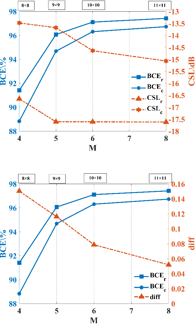
Figure 3: Results of NESSPA under different N: (a) BCE and CSL and (b) BCE and diff.
Table 3: Numerical results of NESSPA under different N
| N | ||||
| M | 4 | 5 | 6 | 8 |
| 91.41 | 96.07 | 97.11 | 97.42 | |
| 88.83 | 94.68 | 96.31% | 96.73% | |
| -16.65 | -17.60 | -17.61 | -17.62 | |
| -13.48 | -13.68 | -14.64 | -15.07 | |
| diff | 0.1504 | 0.1108 | 0.0787 | 0.0519 |
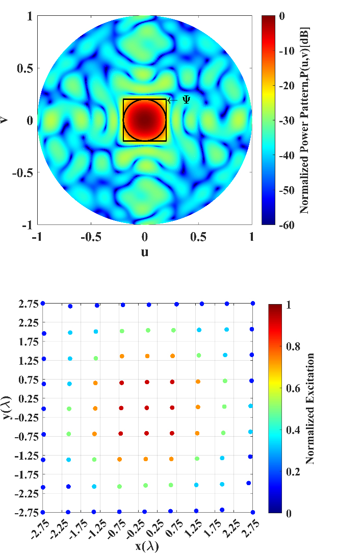
Figure 4: Simulation results of NESSPA (, M=5, BCE=96.07%, CSL=-17.60dB): (a) layout and excitation and (b) normalized power pattern.
The second set of simulation in this section involves synthesis of NESSPA with different , and the corresponding optimal M. The synthesis results are displayed in Fig. 3 and Table 3. From Table 3, it can be seen that when , both can reach more than 91% and the effectiveness of the NDSMOPSO algorithm can thus be demonstrated. When , dividing five subarrays, and when , dividing six subarrays are most suitable for the actual fabrication of the MWPT system.
If we take as an example, Fig. 4 shows the power pattern and layout of the five subarrays. In Fig. 4 (a), most of the radiated energy is concentrated in the receiving region. Therefore, the method can obtain a better array performance. Figure 5 shows the distribution of array element positions before and after optimization by NDSMOPSO algorithm. NDSMOPSO algorithm determines the non-dominated solution based on the fitness value and updates the population during iteration. Each iteration optimizes the array element positions and excitations at the same time, and the performance of the array is improved after optimization.
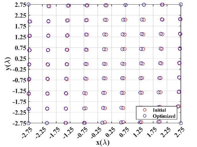
Figure 5: Distribution of transmitting array element positions before and after algorithm optimization.
Table 4: Performance comparison of different array modes
| NESSPA | Ref. [13] | Ref. [22] | Ref. [17] | Ref. [8] | |
| N | 81 | 100 | 316 | 81 | 100 |
| M | 5 | 100 | 4 | 14 | 1 |
| 56% | 100% | 79% | 81% | 100% | |
| 6.2% | 100% | 1.2% | 17.28% | 1%5 | |
| BCE | 96.07% | 96.45% | 92.82% | 95.27% | 91.06% |
| -17.60 | -12.27 | -20.62 | -18.04 | -16.01 |

Figure 6: Comprehensive results of two performance indicators with the number of iterations when M 5.
The multi-objective fitness curve is shown in Fig. 6. Through Fig. 6, the optimal BCE converges at about 20 generations, the optimal diff converges at about 25 generations. They all reach convergence within 40 generations, which demonstrates the fast convergence of the method. The good multi-objective optimization performance of the method is also verified.
B. Comparison of NESSPA with other planar array models in synthesis performance
To gain further validation of the method, we used several comprehensive performance indicators to compare NESSPA with three array optimization models in [8, 13, 17, 22] as shown in Table 4.
From Table 4, it can be seen that the uniformly excited unequally spaced planar array synthesis method based on the chaotic particle swarm optimization (CPSO) algorithm proposed in [8] requires only one power amplifier due to the use of uniform excitation, which can significantly reduce the cost, but has a relatively low BCE (BCE=96.07% BCE=91.06%). A non-uniformly excited planar array model was used in [13] (BCE=96.45% BCE=96.07%) but an amplifier needs to be designed for each array element, which leads to an increase in cost. In contrast, the BCE=96.07% obtained in this paper is only reduced by 0.38% and the CSL is suppressed by 5.33 dB based on the use of fewer array elements and subarrays. Comparing with [22], the synthesized model proposed in this paper can obtain a higher BCE with fewer array elements. Compared with [17], the NDSMOPSO proposed in this paper can simultaneously optimize the array element position and excitation during population updating with evolution. With the same number of array elements, a larger BCE is obtained by using fewer amplifiers, which can better achieve high efficiency and low cost.
V. CONCLUSION
In this paper, we propose a one-step optimization method for planar transmitter arrays in MWPT systems based on NDSMOPSO. We improved the DWPSO algorithm [25] by adding a multi-objective learning factor while the population is updated with the evolutionary process, and established a one-step optimization mechanism so that the algorithm can optimize the element positions and excitations at the same time in each iteration. By comparing with other two-step subarray delineation methods, the method can achieve higher BCE with fewer elements. It is proved that the method can simplify the feeder network and reduce cost.
REFERENCES
[1] X. Zhu, K. Jin, Q. Hui, W. Gong, and D. Mao, “Long-range wireless microwave power transmission: A review of recent progress,” IEEE Journal of Emerging and Selected Topics in Power Electronics, vol. 9, no. 4, pp. 4932-4946, Aug. 2021.
[2] P. Lu, K. Huang, Y. Yang, B. Zhang, F. Cheng, and C. Song, “Space matching for highly efficient microwave wireless power transmission systems: Theory, prototype, and experiments,” IEEE Transactions on Microwave Theory and Techniques, vol. 69, no. 3, pp. 1985-1998, Mar. 2021.
[3] X. Li, B. Duan, L. Song, Y. Zhang, and W. Xu, “Study of stepped amplitude distribution taper for microwave power transmission for SSPS,” IEEE Transactions on Antennas and Propagation, vol. 65, no. 10, pp. 5396-5405, Oct. 2017.
[4] A. Massa, G. Oliveri, F. Viani, and P. Rocca, “Array designs for long-distance wireless power transmission: State-of-the-art and innovative solutions,” Proceedings of the IEEE, vol. 101, no. 6, pp. 1464-1481, June 2013.
[5] C. Peng, Z. H. Ye, Y. H. Xia, and C. Yang, “Analysis on space transmission model of the microwave wireless power transfer system,” Frequenz, vol. 75, no. 11-12, pp. 449-458, 2021.
[6] Y. Song, Y. Liu, W. Xu, X. Yang, and R. Wang, “Research on the multiobjective optimization of microwave wireless power receiving in an unmanned aerial vehicle network,” Complexity, vol. 2020, no. 1, p. 8882528, 2020.
[7] S.-H. Ahn, Y.-S. Choi, M. Elhefnawy, and W.-S. Lee, “Multi-polarized reconfigurable antenna with ground plane slot and capacitance feeding for UAV-to-everything communications,” Applied Computational Electromagnetics Society (ACES) Journal, vol. 38, no. 12, pp. 998-1004, Dec. 2023.
[8] X. Li, B. Duan, J. Zhou, L. Song, and Y. Zhang, “Planar array synthesis for optimal microwave power transmission with multiple constraints,” IEEE Antennas and Wireless Propagation Letters, vol. 16, pp. 70-73, 2017.
[9] F. Yang, S. Yang, Y. Chen, S. Qu, and J. Hu, “An irregular tiled array technique for microwave wireless power transmission,” IEEE Transactions on Vehicular Technology, vol. 72, no. 4, pp. 5257-5273, Apr. 2023.
[10] Q. H. Zhang, Q. H. Zhang, and Z. Y. Shen, “Planar array subarray division method in microwave wireless power transmission based on PSO&K-means algorithm,” IEEE Open Journal of Antennas and Propagation, vol. 4, pp. 520-527, 2023.
[11] K. Vodvarka, M. Jurisic Bellotti, and M. Vucic, “Design of uniformly excited unequally spaced antenna arrays by using nonlinear optimization,” IEEE Antennas and Wireless Propagation Letters, vol. 23, no. 5, pp. 1463-1467, May 2024.
[12] S. Prasad, “On the index for array optimization and the discrete prolate spheroidal functions,” IEEE Transactions on Antennas and Propagation, vol. 30, no. 5, pp. 1021-1023, Sep. 1982.
[13] G. Oliveri, L. Poli, and A. Massa, “Maximum efficiency beam synthesis of radiating planar arrays for wireless power transmission,” IEEE Transactions on Antennas and Propagation, vol. 61, no. 5, pp. 2490-2499, May 2013.
[14] S. Kojima, T. Mitani, and N. Shinohara, “Array optimization for maximum beam collection efficiency to an arbitrary receiving plane in the near field,” IEEE Open Journal of Antennas and Propagation, vol. 2, pp. 95-103, 2021.
[15] J. Li and Z. Han, “Synthesis of sparse square arrays with high beam collection efficiency under minimum element spacing constraints,” Microwave and Optical Technology Letters, vol. 65, no. 1, pp. 240-246, 2023.
[16] J. Li, J. Pan, and X. Li, “A novel synthesis method of sparse nonuniform-amplitude concentric ring arrays for microwave power transmission,” Progress in Electromagnetics Research C, vol. 107, pp. 1-15, 2021.
[17] J. Li and S. Chang, “Novel sparse planar array synthesis model for microwave power transmission systems with high efficiency and low cost,” Progress in Electromagnetics Research C, vol. 115, pp. 245-259, 2021.
[18] J. Li, Z. Han, and C. Guo, “Novel subarray partition algorithm for solving the problem of too low beam collection efficiency caused by dividing a few subarrays,” Progress in Electromagnetics Research M, vol. 108, pp. 223-235, 2022.
[19] X. Li, B. Duan, and L. Song, “Design of clustered planar arrays for microwave wireless power transmission,” IEEE Transactions on Antennas and Propagation, vol. 67, no. 1, pp. 606-611, Jan. 2019.
[20] X. Yang, W. Xi, Y. Sun, T. Zeng, T. Long, and T. K. Sarkar, “Optimization of subarray partition for large planar phased array radar based on weighted K-means clustering method,” IEEE Journal of Selected Topics in Signal Processing, vol. 9, no. 8, pp. 1460-1468, Dec. 2015.
[21] P. Rocca, L. Poli, A. Polo, and A. Massa, “Optimal excitation matching strategy for sub-arrayed phased linear arrays generating arbitrary-shaped beams,” IEEE Transactions on Antennas and Propagation, vol. 68, no. 6, pp. 4638-4647, June 2020.
[22] X. Sun, X. Li, K. Liu, and C. Liu. “Study on the transmitting array for ground microwave wireless power transmission system,” in 2023 IEEE 11th International Conference on Information, Communication and Networks (ICICN), Xi’an, China, pp. 659-663, Aug. 2023.
[23] S. Liang, Z. Fang, G. Li, Y. Zhao, X. Liu, and G. Sun, “An improved multiobjective evolutionary algorithm based on decomposition approach and its application in antenna array beam pattern synthesis,” International Journal of Numerical Modelling: Electronic Networks, Devices and Fields, vol. 35, no. 1, p. e2935, 2022.
[24] M. W. Wolff and J. A. Nanzer, “Application of pseudo weights in antenna array optimization and design,” IEEE Antennas and Wireless Propagation Letters, vol. 23, no. 5, pp. 1478-1482, May 2024.
[25] W. Deng, H. Zhao, X. Yang, J. Xiong, M. Sun, and B. Li, “Study on an improved adaptive PSO algorithm for solving multi-objective gate assignment,” Applied Soft Computing, vol. 59, pp. 288-302, 2017.
BIOGRAPHIES

Jianxiong Li received the B.Sc. and M.Sc. degrees in Physics in 1991 and 1994, respectively, and obtained the Ph.D. degree in Communication and Information System in 2007, from Tianjin University, Tianjin, China. His main research interests are in computational electromagnetics, wireless communication, and antenna.

Ranran Zhang received B.Sc. degree in the School of Physical Science and Information Engineering from Liaocheng University in 2022. She is currently working toward M.Sc. degree in the School of Electronic and Information Engineering from Tiangong University. Her current research interests are electromagnetics, array antennas, and microwave wireless power transmission.

Ziyu Han received M.Sc. degree in the School of Electronic and Information Engineering from Tiangong University in 2023. She is currently working toward Ph.D. degree in the National University of Defense Technology, School of Electronic Science. Her research focuses on distributed beamforming, DOA estimation, array signal processing, and intelligent optimization algorithms.
ACES JOURNAL, Vol. 39, No. 9, 754–761
doi: 10.13052/2024.ACES.J.390901
© 2024 River Publishers