A Dual-polarized Reflectarray Antenna for High-speed Ka-band Satellite Communications
Ahmet Hulusi Gülseren, Selda Yılmaz, Aytaç Alparslan, and Nurhan Türker Tokan
1Department of Electrical-Electronics Engineering
Aydın Adnan Menderes University, Aydın 09010, Türkiye
agulseren@adu.edu.tr
2Department of Electronics and Communication Engineering
Yildiz Technical University, İstanbul 34220, Türkiye
selda.yilmaz@memorial.com.tr, nturker@yildiz.edu.tr
3Department of Electrical and Electronics Engineering
Trakya University, Edirne 22030, Türkiye
aytacalparslan@trakya.edu.tr
Submitted On: September 19, 2024; Accepted On: October 17, 2024
ABSTRACT
A small-sized reflectarray antenna array with compact production specifications is designed and fabricated for high-speed Ka-band communication systems. In the design phase, firstly, the reflection characteristics of unit cells used in the reflective surface are obtained by the full wave computational analysis tool, CST Microwave Studio. Secondly, an aperture efficiency analysis is carried out to determine the physical size of the reflectarray and the distances between the feeding antenna and the individual unit cells. Then, the entire reflectarray antenna is analyzed by array theory to obtain geometrical dimensions to be used in the fabrication phase. These results are verified by CST Microwave Studio and similar fabrication guidelines are obtained for both TE and TM polarizations. In the fabrication phase, the carefully tailored design parameters of the unit cells are used to build the antenna and measure important parameters such as radiation patterns, gain, cross polarization levels and S parameters, which agree with the results obtained in the design phase. The proposed reflectarray antenna makes it possible to support dual-polarized multi-beams in the range 18-20 GHz with stable gain behavior, which makes it possible to use it in high speed 5G satellite communication systems.
Index Terms: Antennas, reflectarrays, satellite communication.
I. INTRODUCTION
The popularity of reflectarray antennas have increased in parallel with improvements in 5G/6G satellite technologies which made it possible to obtain faster communication standards with lower delays [1–5]. Reflectarray antennas are also suitable to be used in a wide range of frequency bands employed in different types of satellites. For instance, a reflectarray antenna was designed using the pattern synthesis method to fulfill the coverage requirements of Direct Broadcast Systems (DBS) in South America in the Ku-band and to obtain the phase distribution at different frequencies in the Transmit (Tx) and Receive (Rx) bands [6]. In another study, a reflectarray antenna was used in a medium Earth orbit remote sensing satellite system by using a Yagi-Uda array as the feeding mechanism in the X-band [7]. Recently, reflectarray antennas have gained popularity in satellite communication studies due to their features such as low cost, ease of production and eliminating the necessity of complex feeding circuits [8, 9]. These features are realized in dual-polarized reflectarray antennas that can be combined with other structures to be used in applications such as transmit-receive reflectarrays, reflect-transmit arrays and plane wave generators [6, 10, 11]. In addition, a linearly polarized reflectarray and a circularly polarized transmit array are combined to have the characteristics of both [6, 12, 13, 14]. As itemized by the applications above, designing and manufacturing reflectarray antennas are among the most popular recent research subjects in aerospace communication systems.
When designing antenna systems for satellite communications, performance, weight, volume, cost and multifunctionality must be considered. Therefore, to use reflectarray antennas in such systems, it is important that the designs are dual polarized, support multi-beams, and operate at different frequencies with low-cost and small-sized production specifications. In dual-polarized reflectarray antenna systems, symmetrical structures are generally favored. For such antennas, single-layer structures are preferred for ease of fabrication and cost [10, 15, 16]. Dual polarization studies are carried out not only in linear polarization but also in circular polarization [17, 18]. The reconfigurable dual-polarized reflectarray antenna is constructed using a single-band, symmetrically rotated subarray to keep the cross polarization levels low [19]. A dual-polarized reconfigurable reflectarray antenna has been designed using independent phase control obtained by adding p-i-n diodes as an active component to the meta-surface elements [19]. While designing the unit cell of the reflectarray in [20], the thickness of the liquid crystal layer was reduced without loss of performance. In another dual-polarized application, a tightly coupled reflectarray antenna consisting of unit cells with x and y polarizations is designed [21], where the reflecting surface for each polarization consists of different number of elements. In another study, an X-band dual-polarized reflectarray antenna using shared aperture technology that has only one substrate between the two metal layers is designed [10], where the number of substrates is reduced when combining the advantages of the elements above and below the substrate. Another method for designing a broadband dual-polarized and dual beam reflectarray antenna is to use a 1-bit unit cell [15]. Generally, a rectangular horn antenna is used as the feed antenna in reflectarray antenna applications, but other antenna models can also be used [6, 14, 22]. In addition, reflectarray antennas can operate simultaneously for one or more bands on two [17, 23, 24, 25] or more frequencies [8].
In this work, a reflectarray antenna is designed, fabricated and measured to be used in downlink frequencies of Ka-band Satellite Communication (SATCOM) [26]. When designing the reflectarray antenna, a single-layer dual-polarized unit cell layout, which was analyzed only numerically in [27], is used. Here, the geometrical parameters of the unit cells are optimized to be used in Ka-band 5G high speed satellites with low-cost and small-sized fabrication specifications. For 18 GHz, the proposed structure has a directivity of 21.72 dBi, a gain of 20.99 dBi and a total efficiency of 84.58%. Very similar results are obtained for TE and TM modes. The antenna gain shows stable characteristics in the 18-22 GHz frequency band. As seen in the results, the reflectarray antenna designed in this paper is a strong candidate to be used in high speed 5G satellite communication systems.
This paper is organized as follows. In section II, the novel unit cell is introduced, and the phase variations obtained by changing the dimensions of the elements in the unit cell are given. In the third section, the characteristics of the feed horn antenna are presented, and the optimum dimensions of the reflective surface are determined by using the aperture efficiencies. Based on these dimensions, a novel reflective surface is designed. In section IV, the designed reflectarray antenna is analyzed by CST Microwave Studio [28] and the array theory method and the results are compared. The parameter measurements of the fabricated reflectarray antenna are shared in the fifth section and the main contributions of this paper are summarized in section VI.
II. UNIT CELL DESIGN
When designing a reflectarray antenna, the unit cells should be accurately analyzed since the performance of whole system depends directly on the unit cell performance. A unit cell structure with symmetry in both principal planes is used for the dual-polarized reflectarray antenna with an off-axis feed. This structure was recently analyzed, only numerically, in a different setting with an on-axis feed [27]. The proposed unit cell geometry is depicted in Fig. 1. As seen in the figure, each unit cell is made up of a cross dipole and four L-shaped elements. The proposed unit cell is printed on a mm thickness Arlon DiClad 880 substrate with the relative electrical permittivity of . To achieve the desired phase difference characteristics, a gap between the substrate and the ground plane is left as free-space with thickness mm. A single-layer structure is preferred in the design of the unit cell due to simple and low-cost fabrication. Design parameters of the element are exhibited in the figure and the values of the parameters are listed in Table 1 . Since the unit cell is rectangular and has identical profile along xz- and yz-planes, the phase of the unit cell for the TE- and TM-polarization is controlled by the lengths of the dipoles. Thus, corresponding phase shift characteristic is obtained by varying the parameter. Analysis of the unit cell is carried out in CST Microwave Studio.
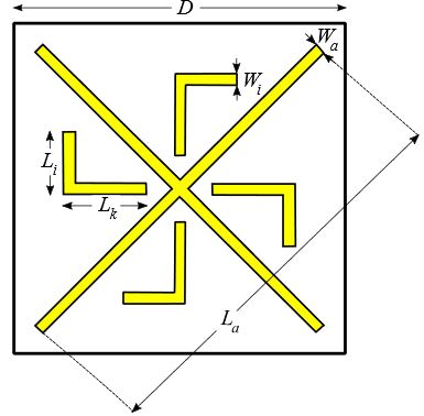
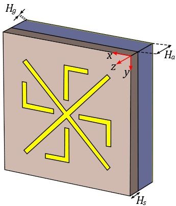
Figure 1: Unit cell of the dual-polarized reflectarray antenna: (a) top view and (b) perspective view.
Table 1: Parameters of the unit cell
| Parameter | Value (mm) |
| 7.5 | |
| 0.25 | |
| 0.25 | |
| 1.4 | |
| 1.86 | |
| 0.51 | |
| 1 | |
| 0.035 |
Periodicity of the unit cell [ parameter in Fig. 1 (a)] should be chosen by considering the required phase shift at the operation band. Besides providing enough space to obtain the phase shift, its value should be chosen to avoid grating lobes at the higher frequencies of the band. The following equation may be used to determine the periodicity of the unit cell [29]:
| (1) |
where is the wavelength in free-space and is the angle of beam radiation with respect to the normal direction of the reflectarray. According to the expression given in equation (1), the horizontal and vertical dimensions of the unit cell at 18 GHz must not exceed mm for . By choosing mm in the proposed unit cell, it is aimed to direct the main beam towards larger reflection angles. The final values of the parameters are determined after an optimization process.
To observe the effects of the unit cell parameters, a comprehensive parametric analysis is carried out. Although they are not reported here for the sake of brevity, important conclusions of the parametric analysis are given. The substrate material plays a critical role in the phase characteristics of the unit cell. Phase variation of the unit cell for different air gap and substrate thicknesses as the function of parameter is given inFig. 2.
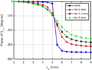
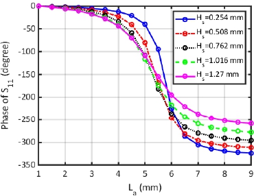
Figure 2: Phase characteristics of the unit cell as a function of parameter at 18 GHz for different (a) air gap values () and (b) substrate thickness values ().
According to Fig. 2 (a), the maximum phase variation at GHz is achieved when there is no air layer between the Arlon substrate and the ground plane (). However, an abrupt decrease is observed in this case. When elements with nonlinear S-shaped phase curves are used in the reflectarray design, they cause narrow operation bands and high variations at different frequencies. Thus, air layer thickness is chosen as mm by virtue of the fact that the phase difference is more, and the phase curve is closer to linear. The total phase variation of the structure for mm is about . Phase characteristics of the unit cell for different substrate thickness values are exhibited in Fig. 2 (b). The phase variations reveal that as the substrate thickness increases, the amount of phase range decreases and the phase curve gets closer to linear. Maximum phase change is observed for mm. Since this thickness is very thin and may cause problems at the surface etching stage of the reflectarray manufacturing process, this thickness is not favored. Among the other thicknesses of Arlon DiClad 880 substrate, mm is chosen.
III. REFLECTARRAY DESIGN
A. Feed antenna: Double ridged horn antenna
As the feed antenna of the system, an OBH180400-15 double ridged horn antenna operating at 18-40 GHz frequency band is used. The broadband feed is linear polarized with high polarization purity. Right-angle double ridge waveguide (WRD180) to coaxial adapter ( mm female) is used for the cable connection. Simulated reflection coefficient variation of the feed antenna is given in Fig. 3.
variation of the horn antenna shows that good impedance matching is achieved above cutoff frequency of the double ridged waveguide. The photograph of the feed antenna is given as an inset in Fig. 3.The three-dimensional radiation pattern of the feed antenna at 18 GHz is shown in Fig. 4, where the beam direction is also demonstrated.
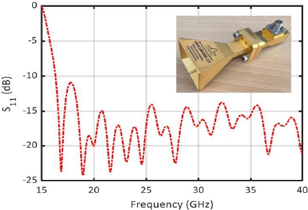
Figure 3: Reflection coefficient variation of the double ridged horn antenna.
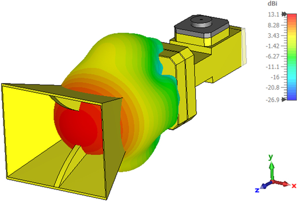
Figure 4: 3D far-field radiation pattern of the feed antenna at 18 GHz.
The gain and phase center of the horn antenna are dBi and mm towards inside from the center of the horn aperture along the z-axis. In the reflectarray system, the phase center of the feed antenna should coincide with the predetermined feed position by aperture efficiency analysis. The gain and position of the feed antenna are critical factors for maximizing aperture efficiency.
B. Aperture efficiency
Aperture efficiency analysis is carried out to determine the physical size of the reflective surface and the distance of the feed antenna’s phase center from the reflective surface. The aperture efficiency of the reflectarray, , is calculated by the product of illumination and spillover efficiencies [30]. Illumination efficiency, , measures how uniform the field amplitude is distributed on the antenna aperture, whereas the spillover efficiency, , is defined as the ratio between the total radiated power and the incident power on the reflectarray [31]. These two parameters are calculated as a function of the shape of the reflectarray and the feeding source.
Radiation patterns of the feed antenna are given in Fig. 5 in two principal planes. Since the aperture of the horn feed antenna is rectangular, the patterns are different in and planes. When determining the parameter of the cos pattern, is chosen by considering the H-plane pattern, which has a wider beam compared to the E-plane. The 3 dB beamwidth of the antenna are approximately and in H- and E-planes, respectively. By using the model for the H-plane of the feed antenna pattern, parameter of the feed antenna is found to be .
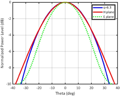
Figure 5: Normalized power levels of the feed antenna. model with 6.3 is depicted by a solid blue line.
For the reflectarray system shown in Fig. 6, the spillover efficiency () is calculated by the ratio of the total power radiated by the feed antenna to the power incident on the reflective surface as given below:
| (2) |
where is the Poynting vector. By using a numerical approach, the following equation can be used to solve for array apertures in the polar coordinate plane [31]:
| (3) | |||
where H is the perpendicular distance between the phase center of the feed antenna and the reflective surface. Illumination efficiency () is calculated as follows:
| (4) |
where stands for the amplitude distribution over the reflective surface, which depends on feed antenna pattern and reflectarray element pattern. Alternatively, the following formula can be used to solve for the array apertures in the polar coordinate plane numerically [31]:
| (5) |
By using the novel dual-polarized unit cell introduced in this paper, an off-axis fed reflectarray system whose feed is located at (z-axis is along the reflectarray surface normal) and beam is oriented towards in plane is designed. The spillover (), illumination () and aperture () efficiency values of the reflectarray system are given in Fig. 7 as a function of the reflectarray diameter for the feed antenna elevation value from the reflective surface of mm.
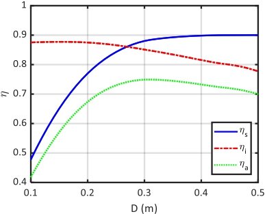
Figure 7: Efficiency as a function of the reflectarray diameter for the off-axis fed reflectarray.
As seen in Fig. 7, has its highest value at mm. In this case, the reflective surface consists of 4040 cells. Since the RAM and processor capacity of the workstation (HP Z820 Intel(R) Xeon(R) workstation with 2.4 GHz processor and 64 GB RAM) used for the simulations cannot handle this processing load, the reflective surface has been reduced to 2525 cells by sacrificing efficiency. This compromise results in reduced aperture efficiency of 0.65.
C. Reflective surface design
Each unit cell is used as an individual reflector when designing the reflective surface of the reflectarray antenna. The finely tuned geometrical features of the unit cells are used to atone for the phase delay generated due to the path differences between the feed antenna and individual unit cells. To design a reflective surface with maximum directivity with off-axis operation, the following equations are used to calculate the required phase shift for each unit cell:
| (7) | ||
| (8) |
where is the reflection phase and is the distance between the feed antenna and the th element. When calculating the relations given above, defines the position vector of the th element, and the unit vector represents the direction of the main beam [32] as shown in Fig. 6. Since a relative reflection phase is needed, is added in (7), where is the wavenumber of free-space. The unit cell and the feed antenna are located at and , respectively.
The necessary phase distribution for steering the beam towards a predefined direction is obtained by using the equations above. The phase values are quantized when designing the reflective surface and smaller quantization steps are used in the fast-decaying regions. To achieve optimum directivity, a phase range of 360 degrees is required. With the dual-polarized novel unit cell, a phase range of 360 degrees is obtained with mm mm. The unit cell phase distribution of the reflective surface consisting of 2525 cells is shown in Fig. 8 (a). The reflectarray with the corresponding unit cells geometry that gives the calculated phase value is given in Fig. 8 (b).
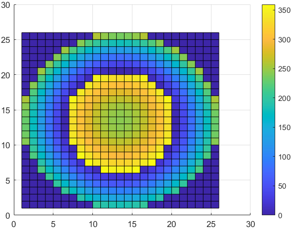
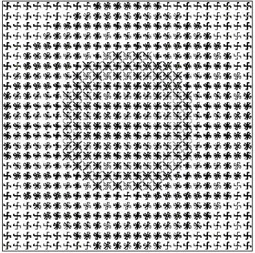
Figure 8: Reflective surface of the reflectarray: (a) phase distribution and (b) reflectarray with corresponding unit cells geometry.
IV. ANALYSIS RESULTS
A reflectarray with 2525 dual-polarized unit cells was analyzed with a full-wave electromagnetic wave analysis tool based on finite-integration technique [28]. The problem space consists of about 134 million unknowns. Array theory, which is a robust analysis technique for electrically large antennas, gives very fast results compared to other analysis methods. 3D simulation programs especially take a while, whereas array theory calculates the far-field radiation pattern of the reflectarray antenna in seconds. The far-field radiation pattern of a reflectarray antenna consisting of MN elements is calculated by [32]:
| (9) |
| (10) |
where and are the vector functions defined for the unit cell patterns and the unit cell excitations and the remaining vectors and angles in the equations are defined in Fig. 6. The scalar element pattern function is given with model as follows:
| (11) |
The incident field and the element property are used to define element excitation function, defined by:
| (12) |
where isn directly obtained from the unit cell analysis. Finally, the radiation pattern of the reflectarray is obtained as:
| (13) | |||
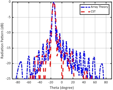
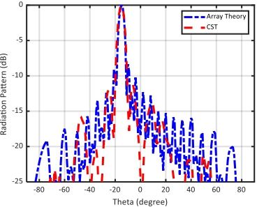
Figure 9: Normalized radiation patterns at 18 GHz: (a) TE and (b) TM polarization.
General pattern shape indicators, especially the main beamwidth and the beam direction, are obtained successfully by the array theory. However, the cross polarization characteristics of the antenna are not calculated by array theory since the feed polarizations are not included and a simplified model is used. To get the radiation pattern data in different polarizations, full wave simulations are performed using CST Microwave Studio. Normalized radiation patterns of the dual-polarized reflectarray antenna designed for high-speed Ka-band satellite communications are given in Fig. 9 for TE and TM polarizations. The feed phase center is located at ( mm, , mm) with respect to the center of the reflectarray. Gain of and dBi is observed in TE and TM modes, respectively.
It is observed that array theory and simulation results are almost overlapping for both modes and in both cases the main beam is directed to . Moreover, TE and TM mode patterns are almost identical with main beams directed towards . This proves that the reflectarray works in dual mode successfully. The effect of the holder is investigated by full wave analysis of the whole structure. Figure 10 shows the 3D radiation pattern in TE mode. The gain pattern, which is obtained by including the holder in the simulations, has a maximum value of dBi. Inclusion of the holder to the simulations has lowered the gain about dB and increased the side lobe level of the pattern. Since the unit cell structure used in this design is symmetrical in the and directions, TE and TM modes are identical.
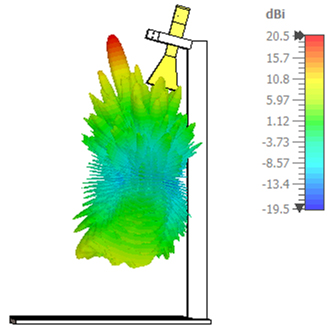
Figure 10: Three-dimensional radiation pattern of reflectarray antenna in TE mode. The pattern is obtained by including the holder with PLA (polylactic acid) material.
V. EXPERIMENTAL VERIFICATION
A. Fabrication
The reflectarray prototype consisting of 2525 dual-polarized unit cells is fabricated by a chemical etching technique. Arlon DiClad 880 with mm dielectric thickness and copper thickness is used as the printed circuit board. The reflectarray prototype which has 187.5 mm mm physical area is shown in Fig. 11 (a) with an expanded view of a unit cell. The ground plane of the reflectarray is generated by covering the top surface of the flat holder plate by conductive tape. An air layer with mm thickness is ensured between the substrate and the ground plane by using mm nuts. A double ridged horn antenna (OBH180400-15 from Ocean Microwave) operating in the GHz frequency band is used as the feed antenna. The phase center of the horn antenna at GHz is located to (mm, , mm) coordinates with respect to the center of the reflectarray. A holder that is designed to keep the feed antenna and reflectarray stationary in their designated positions is printed with a PLA filament by using an additive manufacturing technique. Four holes are drilled in the corners of the reflectarray and 5M screws are used to fix the reflectarray to the holder mechanism as shown in Fig. 11 (b). The arm of the holder grips the horn antenna with a clamp that orients the main beam of the feed antenna towards the center of the reflectarray with .
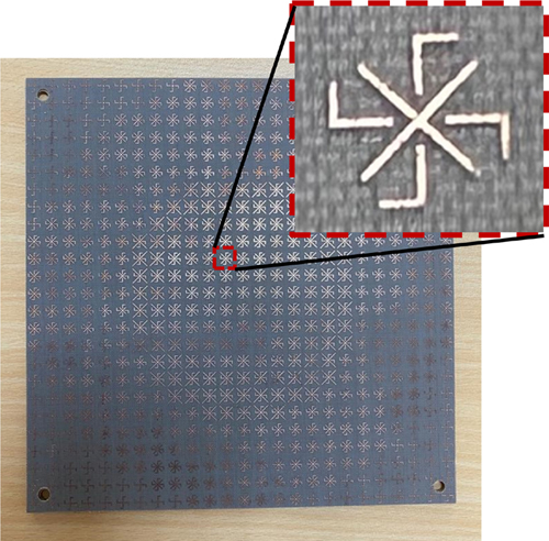
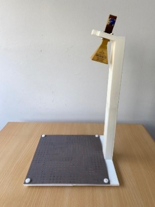
Figure 11: Fabricated reflectarray system: (a) reflectarray prototype and (b) reflectarray system.
B. Measurement results
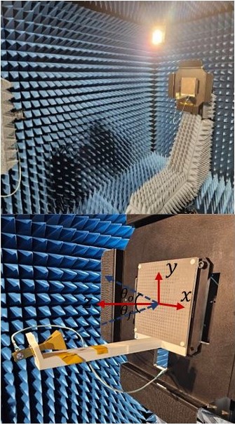
Figure 12: Measurement setup of the dual-polarized Ka-band reflectarray system. Beam steering is observed on the plane.
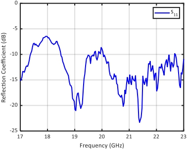
Figure 13: Measured parameter variation of the reflectarray system as a function of frequency.
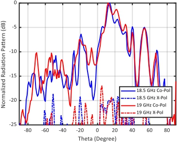
Figure 14: Measured normalized patterns of the reflectarray system on the plane. Solid lines (—) and dash-dot lines (– -) belong to Co-polarized and X-polarized patterns, respectively.
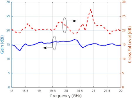
Figure 15: Measured gain and cross polarization level variations.
Co- and X-polarized radiation patterns, antenna gain and reflection coefficients of the reflectarray system are measured in a full anechoic chamber in the 17-23 GHz frequency band. An NSI-RF-SG42 horn antenna is used as the reference antenna in the measurements. The measurements are performed with 1 resolution within angular range at the steering plane of the reflectarray. The measurement setup in the anechoic chamber is shown in Fig. 12.
Reflection coefficient variation of the reflectarray system is given in Fig. 13. The reflectarray has good impedance matching characteristics with lower than dB above GHz except for a slight increase in the GHz band. At GHz, about dB reflection coefficient level is observed at the measurement, which wasn’t the case in the simulations. This deviation from simulated response is attributed to the introduction of the connector. Co- and X-polarized radiation patterns are demonstrated in Fig. 14 at and GHz. It is clearly observed that the main beam of the measured patterns is towards in the plane. The observed sidelobe levels are higher compared to the simulation results. In the measurement process, the absorbers around the reflectarray were removed to fit the reflectarray system. The higher sidelobes that were not observed in the simulations are attributed to the conductor region where the bottom of the reflectarray was implanted. Measured gain and cross polarization levels are given in Fig. 15. Although the antenna was optimized to operate at 18 GHz, the antenna gain shows stable characteristics in the whole frequency range. Measured cross polarization patterns are at low levels. Mostly it is above dB in the GHz range. The radiation performance of the reflectarray may be enhanced in terms of sidelobe and efficiency by enlarging the physical reflectarray size since larger dimensions reduce effects such as edge diffraction, specular reflection and feed blockage.
VI. CONCLUSION
In the transition of 5G to 6G networks, satellites having faster communication standards with lower delays will play a critical role in providing coverage and resilience. Reflectarray antennas are suitable to be used in a wide range of frequency bands employed in different types of satellites. In this work, a novel single-layer dual-polarized unit cell is proposed for a dual-polarized reflectarray antenna operating at SATCOM Ka-Band downlink frequencies to be used in 5G/6G antennas. The unit cell is constructed as the combination of a cross dipole and four L-shaped elements. At 18 GHz, the designed structure has a simulated directivity of 21.72 dBi, a gain of 20.99 dBi and total efficiency of 84.58%. Very similar results are obtained for TE and TM modes. A prototype consisting of 2525 dual-polarized unit cells was fabricated using Arlon DiClad 880 PCB with mm dielectric thickness and m copper thickness and the reflectarray system was measured in a full anechoic chamber. The antenna gain showed stable characteristics in the 18-22 GHz frequency band. It was observed in the simulation and measurement results that the reflectarray consisting of the proposed unit cells produces pencil beams with orientation. The results show that the proposed reflectarray system can be used in high speed 5G satellite communication systems.
ACKNOWLEDGMENT
This work was supported by The Research Fund of Yildiz Technical University (Project Number: FBA-2021-4493). The authors wish to acknowledge Dr. İbrahim Tekin and SUNUM (Sabanci University NanoTechnology Research and Application Center, Istanbul, Türkiye) staff for their assistance with the measurements.
REFERENCES
[1] M. H. Dahri, M. I. Abbasi, M. H. Jamaluddin, and M. R. Kamarudin, “A review of high gain and high efficiency reflectarrays for 5G communications,” IEEE Access, vol. 6, pp. 5973-5985, 2018.
[2] P. Mei, S. Zhang, and G. F. Pedersen, “A low-cost, high-efficiency and full-metal reflectarray antenna with mechanically 2-D beam-steerable capabilities for 5G applications,” IEEE Trans. Antennas Propag., vol. 68, no. 10, pp. 6997-7006, Oct. 2020.
[3] Y. Cui, R. Bahr, S. A. Nauroze, T. Cheng, T. S. Almoneef, and M. M. Tentzeris, “3D printed ‘Kirigami’-inspired deployable bi-focal beam-scanning dielectric reflectarray antenna for mm-wave applications,” IEEE Trans. Antennas Propag., vol. 70, no. 9, pp. 7683-7690, Sep.2022.
[4] P. Mei, S. Zhang, and G. F. Pedersen, “A wideband 3-D printed reflectarray antenna with mechanically reconfigurable polarization,” IEEE Antennas Wirel. Propag. Lett., vol. 19, no. 10, pp. 1798-1802, Oct. 2020.
[5] H. Kim, S. Oh, S. Bang, H. Yang, B. Kim, and J. Oh, “Independently polarization manipulable liquid-crystal-based reflective metasurface for 5G reflectarray and reconfigurable intelligent surface,” IEEE Trans. Antennas Propagat., vol. 71, no. 8, pp. 6606-6616, Aug. 2023.
[6] J. A. Encinar, M. Arrebola, L. F. de la Fuente, and G. Toso, “A transmit-receive reflectarray antenna for direct broadcast satellite applications,” IEEE Trans. Antennas Propagat., vol. 59, no. 9, pp. 3255-3264, Sep. 2011.
[7] S. A. M. Soliman, E. M. Eldesouki, and A. M. Attiya, “Analysis and design of an X-band reflectarray antenna for remote sensing satellite system,” Sensors, vol. 22, no. 3, p. 1166, Feb. 2022.
[8] R. Deng, S. Xu, F. Yang, and M. Li, “An FSS-backed Ku/Ka quad-band reflectarray antenna for satellite communications,” IEEE Trans. Antennas Propag., vol. 66, no. 8, pp. 4353-4358, Aug. 2018.
[9] M. Bozzi, S. Germani, and L. Perregrini, “Performance comparison of different element shapes used in printed reflectarrays,” IEEE Antennas Wireless Propag. Lett., vol. 2, pp. 219-222, 2003.
[10] W. Song, Q. Xue, Y. Cai, N. Guo, K. Liu, S. Li, and H. Ding, “A single-layer reflect-transmit-array antenna with polarization-dependent operation,” IEEE Access, vol. 9, pp. 167928-167935, Nov. 2021.
[11] Á. F. Vaquero, R. Florencio, M. R. Pino, and M. Arrebola, “Dual-polarized near-field plane wave generator using an offset-optics reflectarray mm-wave band,” IEEE Trans. Antennas Propag., vol. 70, no. 12, pp. 12370-12375, Dec. 2022.
[12] B. Xi, Y. Cai, Y. Wang, S. Yang, R. Zang, and L. Zhang, “Design of a dual-polarized reflect-transmit-array,” Microw. Opt. Technol. Lett., vol. 62, no. 2, pp. 949-955, Feb. 2020.
[13] S. Yang, Z. Yan, T. Zhang, M. Cai, F. Fan, and X. Li, “Multifunctional tri-band dual-polarized antenna combining transmitarray and reflectarray,” IEEE Trans. Antennas Propag., vol. 69, no. 9, pp. 6016-6021, Sep. 2021.
[14] C. C. Chung, F. P. Lai, S. X. Huang, and Y. S. Chen, “Anisotropic metasurface with asymmetric propagation of electromagnetic waves and enhancements of antenna gain,” IEEE Access, vol. 9, pp. 90295-90305, 2021.
[15] J. Yin, Q. Lou, H. Wang, Z. N. Chen, and W. Hong, “Broadband dual-polarized single-layer reflectarray antenna with independently controllable 1-bit dual beams,” IEEE Trans. Antennas Propag., vol. 69, no. 6, pp. 3294-3302, June 2021.
[16] Y. Liu, H. Wang, and X. Dong, “Design of a dual polarized broadband single-layer reflectarray based on square spiral element,” Progress in Electromagnetics Research M., vol. 72, pp. 23-30, Aug. 2018.
[17] R. Florencio, D. Martinez-de-Rioja, E. Martinez-de-Rioja, J. A. Encinar, R. R. Boix, and V. Losada, “Design of Ku- and Ka-band flat dual circular polarized reflectarrays by combining variable rotation technique and element size variation,” Electronics, vol. 9, no. 6, p. 985, June 2020.
[18] S. Mener, R. Gillard, R. Sauleau, A. Bellion, and P. Potier, “Dual circularly polarized reflectarray with independent control of polarizations,” IEEE Trans. Antennas Propag., vol. 63, no. 4, pp. 1877-1881, Apr. 2015.
[19] N. Zhang, K. Chen, J. Zhao, Q. Hu, K. Tang, J. Zhao, T. Jiang, and Y. Feng, “A dual-polarized reconfigurable reflectarray antenna based on dual-channel programmable metasurface,” IEEE Trans. Antennas Propag., vol. 70, no. 9, pp. 7403-7412, Sep. 2022.
[20] P. Aghabeyki, Y. Cai, G. Deng, Z.-H. Tan, and S. Zhang, “A dual-polarized reconfigurable reflectarray with a thin liquid crystal layer and 2-D beam scanning,” IEEE Trans. Antennas Propag., vol. 71, no. 4, pp. 3282-3293, Apr. 2023.
[21] W. Li, H. Tu, Y. He, L. Zhang, S.-W. Wong, and S. Gao, “A novel wideband tightly coupled dual-polarized reflectarray antenna,” IEEE Trans. Antennas Propag., vol. 71, no. 6, pp. 5422-5427, June 2023.
[22] L. X. Wu, Q. Hu, X. Y. Luo, J. Zhao, T. Jiang, K. Chen, and Y. Feng, “Wideband dual-feed dual-polarized reflectarray antenna using anisotropic metasurface,” IEEE Antennas Wirel. Propag. Lett., vol. 21, no. 1, pp. 129-133, Jan. 2022.
[23] I. Aryanian, A. Ahmadi, M. Rabbani, S. Hassibi, and M. Karimipour, “Design and fabrication of a dual-polarized, dual-band reflectarray using optimal phase distribution,” Turk. J. Elec. Eng. & Comp. Sci., pp. 878-888, Mar. 2019.
[24] S. Li, Y. Cao, Y. B. Zhang, and T. Wu, “Dual polarized reflectarray antenna for operation in X and Ku bands,” Microwave Opt. Technol. Lett., vol. 64, no. 7, pp. 1272-1279, Mar. 2022.
[25] M. Abdollahvand, K. Forooraghi, J. A. Encinar, Z. Atlasbaf, and E. Martinez-de-Rioja, “A 20/30 GHz reflectarray backed by FSS for shared aperture Ku/Ka-band satellite communication antennas,” IEEE Antennas Wirel. Propag. Lett., vol. 19, no. 4, pp. 566-570, Apr. 2020.
[26] C. McLain, S. Panthi, M. Sturza, and J. Hetrick, “High throughput Ku-band satellites for aeronautical applications,” in MILCOM 2012 - 2012 IEEE Military Communications Conference, Orlando, FL, pp. 1-6, 2012.
[27] S. Yılmaz, A. H. Gülseren, and N. T. Tokan, “Dual-polarized reflectarray for high-speed satellite communication,” in 2023 10th International Conference on Recent Advances in Air and Space Technologies (RAST), Istanbul, Turkiye, pp. 1-5,2023.
[28] CST Microwave Studio [Online]. Available: http://www.cst.com/2023.
[29] E. Nido, “New advances on multi-frequency and multi-beam reflectarrays with application to satellite antennas in Ka-band,” Doctoral thesis, Universidad Politécnica De Madrid, Madrid,2018.
[30] J. Huang, “Analysis of a microstrip reflectarray antenna for microspacecraft application,” Telecommunications and Data Acquisition Progress Report, vol. 120, pp. 153-173, Feb.1994.
[31] A. Yu, F. Yang, A. Z. Elsherbeni, J. Huang, and Y. Rahmat-Samii, “Aperture efficiency analysis of reflectarray antennas,” Microw. Opt. Technol. Lett., vol. 52, no. 2, pp. 364-372, Dec. 2009.
[32] P. Nayeri, “Advanced design methodologies and novel applications of reflectarray antennas reflectarray antennas,” Electronic Theses and Dissertations, University of Mississippi, 2012.
BIOGRAPHIES

Ahmet Hulusi Gülseren received the B.S degree, M.S degree and Ph.D. degree in Electronics and Communications Engineering from Yildiz Technical University (YTU), Istanbul, Turkey, in 2014, 2018 and 2024 respectively. In 2016, he joined the faculty of Electrical and Electronics Engineering Department of Aydın Adnan Menderes University, Aydın, Türkiye, where he is currently research assistant. His research interests include antennas, metamaterials and microwave circuits.

Selda Yilmaz was born in 1994. She received the B.S. and M.S. degrees from the Yildiz Technical University, in Istanbul, in 2016 and in 2023, both in Electronic and Communication Engineering. Her research interest is antenna communication.

Aytaç Alparslan received the B.S. and M.S. degrees in electrical and Electronic Engineering from Koç University, İstanbul, Türkiye, in 2006 and 2008, respectively, and the Ph.D. degree in Information Technology and Electrical Engineering from ETH Zürich in 2013. From 2013 to 2014, he was a postdoctoral fellow at the Institute of Electromagnetic Fields at ETH Zürich. In 2014, he joined the faculty of Electrical and Electronics Engineering Department of Trakya University, Edirne, Türkiye, where he is currently an associate professor. His research interests include computational electromagnetics, metamaterials, layered media and plasmonics.

Nurhan Türker Tokan received her B.Sc. degree in Electronics and Communications Engineering from Kocaeli University in 2002 and her M.Sc. and Ph.D. degrees in Communication Engineering from Yildiz Technical University (YTU), Istanbul, Turkey, in 2004 and 2009, respectively. From May 2003 to May 2009, she worked as a research assistant in the Electromagnetic Fields and Microwave Technique Section of the Electronics and Comm. Eng. Dept. of YTU, Istanbul, Turkey. Between May 2009 and April 2015, she worked as an assistant professor and between April 2015 and August 2021, she worked as an associate professor in the Electronics and Comm. Eng. Dept. of YTU. Since August 2020, she has been working as a professor at the same department. From October 2011 to October 2012, she was Postdoctoral researcher in the EEMCS Department of Delft University of Technology, Delft, Netherlands. From October 2012 to May 2013, she was a Postdoctoral Fellow supported by European Science Foundation at the Institute of Electronics and Telecommunications (IETR), University of Rennes 1, Rennes, France. She is the author or coauthor of more than 50 papers published in peer-reviewed international journals and conference proceedings. Her current research interests are analysis and design of antennas with emphasis on dielectric lens antennas and wideband antennas, microwave circuits and intelligent systems.
ACES JOURNAL, Vol. 39, No. 9, 762–772
doi: 10.13052/2024.ACES.J.390902
© 2024 River Publishers