A Local Transition Adaptive Structured Mesh Generation Method for Finite Difference Time Domain Simulation
Zixuan Cao, Chunhui Mou, Chenghao Wang, Juan Chen, Shaolong Li, Cuirong Zhao, and Yuemeng Yin
1Department of Information Engineering
University of Xi’an Jiaotong University, Xi’an, Shaanxi, China
1759011472@qq.com, mouchunhui@xjtu.edu.cn, chen.juan.0201@mail.xjtu.edu.cn
2China Research Institute of Radiowave Propagation
Qingdao, Shandong, China
wch_gpr@163.com, lsl505@126.com, cuirongzh@163.com, cecilia768@163.com
Submitted On: September 29, 2024; Accepted On: December 4, 2024
ABSTRACT
In this paper, a local transition adaptive structured mesh generation method is proposed for finite difference time domain (FDTD) simulation. This innovative approach can automatically identify the location of the medium interfaces and boundaries based on the triangular facet of the target, and subsequently divide the entire computational domain into numerous subregions. In the subregions, uniform mesh lines are initially placed in accordance with the numerical requirement of FDTD method. Subsequently, part of these meshes are refined based on target structure. Finally, local transition processing is performed for meshes with large variations at the boundaries of neighboring subregions, so that there is no rapid change in mesh size in the boundary position. Different from the existing automatic non-uniform mesh generation methods, the method proposed only adds transition meshes at the medium interfaces and boundaries instead of placing global gradient meshes, so it can greatly reduce the mesh quantity and simplify the mesh generation process. Two classical models of inverted-F antenna and cross-slot frequency selective surface are employed as examples to verify the validity of our method. Simulation results demonstrate that this generation method can achieve nearly equivalent simulation accuracy as the global gradient mesh generation method with a markedly reduced number of meshes.
Index Terms: Finite difference time domain (FDTD), local transition adaptive mesh, structured mesh.
I. INTRODUCTION
The finite difference time domain (FDTD) method is one of the mainstream methods in electromagnetic computing. The essence of the FDTD method is to simulate the propagation process of electromagnetic wave through discretized spatial and temporal meshes, in which the spatial mesh is also known as the Yee cell [1]. Figure 1 shows a Yee cell, which contains both electric and magnetic field components. Specifically, the E-components are located at the middle of the edges and the H-components are located at the center of the faces.
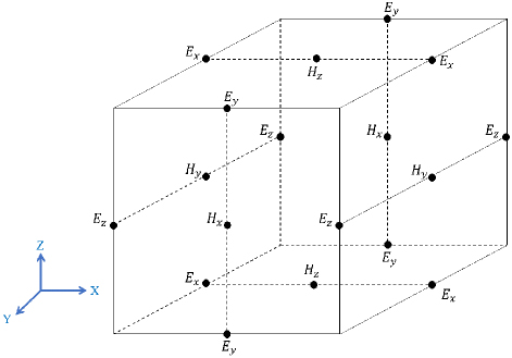
Figure 1: The Yee cell.
It is well known that the quality of the generated mesh has an important influence on the computational accuracy and efficiency of FDTD simulation. Generally, a higher mesh density typically results in a more accurate representation of physical phenomena. However, if the meshes are excessively fine, it can significantly increase computational demands, thereby lengthening simulation time and escalating resource consumption. Therefore, conducting in-depth research on the FDTD mesh generation algorithm and exploring an optimized mesh generation method that can balance the number and quality of meshes is of great significance for promoting the further development of FDTD technology.
In the early stage of the FDTD method, the uniform mesh is mainly used for calculation. However, with increasing demand for electromagnetic simulation and the increasing complexity of target structures, uniform meshes show obvious limitations in dealing with complex geometries and non-uniform media. Therefore, non-uniform mesh generation methods are gradually being introduced to better adapt to these complex situations. The non-uniform mesh generation method allows for the placement of fine mesh in areas with intricate structures and significant field changes, while using coarser mesh in other parts. This approach can ensure calculation accuracy while reducing the total number of meshes, thereby accelerating the overall calculation speed [2–20].
Sun et al. [2] presented a program to generate automatically a three-dimensional surface FDTD mesh for a complex object enclosed by conducting and thin-dielectric surfaces in 1993. Yang and Chen [3] came up with a three-dimensional, automatically adjustable, non-uniform orthogonal-mesh generator in 1999. In this paper, the mesh sizes must smoothly and gradually increase or decrease, because a rapid change in mesh size could result in a significant phase error. Fernandes [11] presented a new software package for antenna analysis and design using the FDTD method in 2007. This software package limits the ratio between the sizes of two adjacent meshes between 0.77 and 1.3. Similar setting is also shown in [12, 13]. Kim et al. [14] proposed a non-uniform sub-grid mesh configuration to increase the stability margin by separating interpolation-error and dislocation-error planes in 2012. The author also applied an adaptive interpolation technique to increase the simulation accuracy. Zhu et al. [15] adopted the intersection parity method for mesh generation in the same year. Their paper introduces the parity of intersections number method for meshing and uses the method of winding numbers to determine the position of intersections relative to triangular facets. Chen et al. [20], in 2024, presented an adaptive mesh generation method which can effectively balance simulation accuracy, and computational resource usage to a certain extent, by increasing the mesh density in areas requiring high precision and reducing the mesh density in other areas. That paper doesn’t limit the ratio of the sizes of two adjacent meshes.
Previous non-uniform mesh generation methods usually impose limitations on the size ratio between adjacent meshes. Applying this restriction to all meshes in the model not only complicates the mesh generation process but also significantly increases the overall mesh quantity. In this paper, a local transition adaptive structured mesh generation method is proposed on the basis of the adaptive structured mesh generation method in [20]. The proposed mesh generation method only adds transition meshes at the media interfaces and boundaries, which can greatly reduce the mesh quantity and simplify the mesh generation process. The detailed operations are as follows. Firstly, find the locations of media interfaces and boundaries of the model and divide the entire computational domain into numerous subregions. Then, the subregions are divided according to numerical requirement of the FDTD method and the target geometry structure. Finally, judge whether the ratio of the mesh size on both sides of adjacent subregions exceeds a certain value. If the ratio exceeds the limit value, add some transition meshes at this location. Two classical models of inverted-F antenna and cross-slot frequency selective surface are simulated as examples. The S and radiation pattern of the inverted-F antenna excited by a discrete port are calculated, and the radar cross section (RCS) of the cross-slot frequency selective surface excited by plane wave is calculated. The results show that, compared with the adaptive generation method, the proposed method can achieve considerable improvement in simulation accuracy at the cost of increasing the mesh quantity by a small amount.
II. METHOD
The proposed mesh generation method consists of three steps:
-
Identify the target boundaries and medium interfaces and place mesh lines at these locations, so that the entire calculation area will be divided into several sub-areas.
-
In the subregions, non-uniform mesh lines are placed according to the numerical requirements of FDTD method and the target structure.
-
Local transition processing is carried out on the meshes with large changes at the boundaries of adjacent subregions, so that the mesh size of the boundary region will not change rapidly.
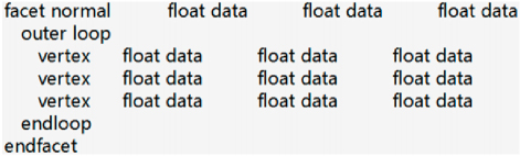
Figure 2: Format of a triangle element in a stl file.
In step 1, the media interfaces and target boundaries are obtained according to the triangle element in the stl file of the model. Figure 2 shows the format of a triangle element in the stl file. Each triangle element is described with its facet normal vector and vertex coordinates and ends with “endfacet”. Based on the vertex coordinates, we can easily get the vectors where the three sides of the triangle elements are located, as shown in Fig. 3. We determine the intersection relationship between the sides of the triangular element and the coordinate axes through dot product operation. We find the sides parallel to any coordinate axis, and the positions of these sides are media interfaces or target boundaries.
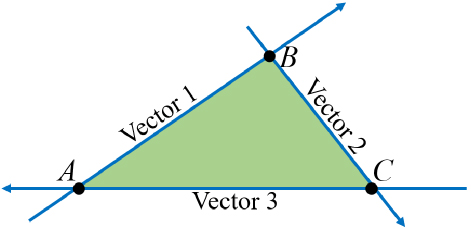
Figure 3: Triangular element and the vectors.
Subsequently, the meshes on both sides of the media interfaces and target boundaries are transacted. Assume the ratio of mesh sizes on both sides of the interface is . If meets the following conditions:
| (1) |
then the larger mesh will be divided equally into two meshes. If meets the following conditions:
| (2) |
then the larger mesh is divided into two meshes, one of which is equal to the size of the smaller mesh. Both and are constants and can be adjusted according to the need, here taking as 1.5 and as 2.
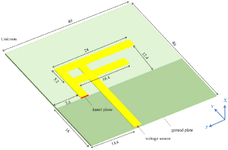
Figure 4: Geometry of the inverted-F antenna.
Let us choose inverted-F antenna as an example. Its model is shown in Fig. 4. The inverted-F antenna has three layers. The first layer is an inverted-F shaped pec patch with a thickness of 0.262 mm and width of 2.4 mm. The second layer is a substrate with a dielectric constant of 2.2 and thickness 0.786 mm. The third layer is the ground with a thickness of 0.262 mm, and its material is pec. The ground is connected to the patch with a pec piece, and the width of the piece is 0.4 mm. The simulation frequency is set to 1-4 GHz.
Firstly, the antenna is preliminarily discretized according to step 1 and step 2. Since the minimum wavelength in the simulation frequency band is 50 mm, the maximum mesh size of the entire space is set to one in twenty-five of the minimum wavelength 2 mm, and the minimum mesh size is set to 0.1 mm. The generation result in the YOZ plane is shown in Fig. 5. The yellow mesh represents the pec patch, and the blue mesh represents the medium substrate.
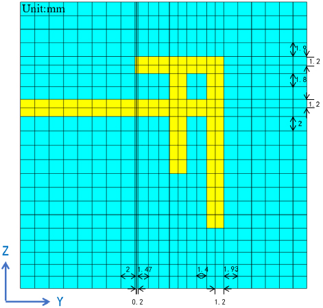
Figure 5: Meshes in YOZ plane of the inverted-F antenna obtained with the method in [20].
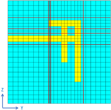
Figure 6: Meshes in YOZ plane of the inverted-F antenna obtained with the proposed method.
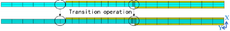
Figure 7: Meshes in XOY plane of the inverted-F antenna obtained with the method in [20] and the proposed method.
Firstly, we can find from Fig. 5 that, at some boundaries of the pec patch, the ratio of mesh sizes on both sides exceeds 1.5 or 2. Therefore, according to the proposed mesh generation method in this paper, we need to add transition meshes at these positions. The new meshes of the antenna are shown in Fig. 6. The red mesh lines in Fig. 6 are the new mesh lines. The meshes in the XOY plane are shown in Fig. 7.
It can be seen that in the X direction, which is also the thickness direction, we add transition meshes at the interface between the medium substrate and the ground, and the interface between the pec patch and the medium substrate, respectively. In the Y and Z direction, there are very few mesh lines added. The addition of these transitional grids ensures that there is no rapid change in mesh size in the boundary region, which increases the precision of mesh generation to some extent.
III. NUMERICAL EXAMPLES
The inverted-F antenna shown in Fig. 4 is simulated with the FDTD method and it is excited with a discrete port. Figure 8 shows the S curves of the inverted-F antenna obtained by the uniform mesh generation method, the adaptive mesh generation method in [20], and the proposed mesh generation method in this paper. The size of the uniform mesh is 0.4 mm in the Y and Z direction and 0.262 mm in the X direction. This set of uniform meshes is finer and has a larger mesh quantity, so its simulation result can be considered as a reliable standard. The S curve simulated by CST Studio Suite (CST) software is also given in Fig. 8. CST’s maximum mesh size is set to 2 mm, and the minimum mesh size is set to 0.1 mm. The ratio of the two adjacent meshes is between 0.77 and 1.3.
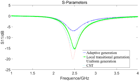
Figure 8: S of the inverted-F antenna simulated by FDTD based on three mesh generation methods and CST.
The results show that, the value of S at 2.46 GHz obtained by the adaptive mesh generation method in [20] is 7 dB, which is quite different from the values obtained by the uniform mesh generation method and CST software. However, the S-curve calculated by the proposed method are in good agreement with those obtained by the uniform grid generation method and CST software.
Figure 9 shows the radiation pattern calculated at 2.46 GHz on the XOZ plane. The FDTD simulation result based on the proposed method is between the results of the uniform mesh generation method and the adaptive mesh generation method, and the simulation result is more accurate without increasing the mesh quantity by a big amount.
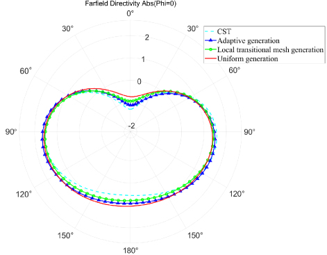
Figure 9: Radiation pattern of the inverted-F antenna simulated by FDTD based on three mesh generation methods and CST.
Mesh quantity and FDTD simulation time based on different generation methods are shown in Table 1.
Table 1: Mesh quantity and simulation time of inverted-F antenna based on different generation methods
| Generation Method | Mesh Quantity | Simulation Time |
| Adaptive generation | 7830 | 29 min 46 s |
| Local transition generation |
13888 | 33 min 11 s |
| Uniform generation | 97344 | 1 h 26 min 30 s |
| CST | 44548 | / |
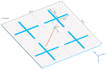
Figure 10: Geometry of the cross-slot frequency selective surface.
Table 1 shows that, based on the adaptive mesh generation method, the proposed mesh generation method increases the mesh quantity and simulation time by just a small amount. If we limit the ratio of all adjacent meshes, the mesh quantity would increase largely.
Let us select the cross-slot frequency selective surface as an example. Its model is shown in Fig. 10. The cross-slot frequency selective surface model has two layers. The first layer is a pec patch with four cross-shaped slots. Its thickness is 1.5 mm and the width of the cross-slot is 2 mm. The second layer is a medium substrate with a thickness of 3 mm and its dielectric constant is 4.4. The simulation frequency is set to 0-4 GHz.
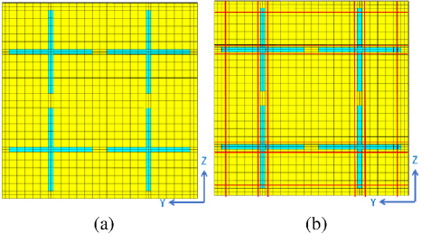
Figure 11: Meshes in YOZ plane of the cross-slot frequency selective surface obtained with (a) the method in [20] and (b) the proposed method.
Since the minimum wavelength in the simulation frequency band is 35.8 mm, the maximum mesh size of the entire space is set to one-tenth of the minimum wavelength at 3.58 mm, and the minimum mesh size is set to 0.1 mm. The results in the YOZ plane of the mesh generation method in [20] and the proposed generation method in this paper are shown in Figs. 11 (a) and (b), respectively. In Fig. 11, the yellow mesh represents the pec patch, while the blue mesh represents the medium substrate. The red mesh lines in Fig. 11 (b) are the new added transition mesh lines. The mesh generation results in the XOY plane are shown in Fig. 12.
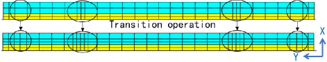
Figure 12: Meshes in XOY plane of the cross-slot frequency selective surface obtained with the method in [20] and the proposed method.
The cross-slot frequency selective surface is excited by a plane wave propagating in the positive direction of the X-axis and polarizing in the positive direction of the Z-axis. A near-field probe is placed one wavelength away from the medium substrate on the X-axis. Figure 13 shows the time-domain waveform of the probe simulated by FDTD based on the two groups of meshes and CST. CST’s maximum mesh size is set to 3.58 mm, and the minimum mesh size is set to 0.1 mm. The ratio of two adjacent meshes is between 0.77 and 1.3.
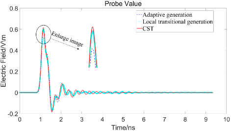
Figure 13: Time-domain waveform of the near-field probe of the cross-dipole frequency selective surface simulated by FDTD based on two groups of meshes and CST.
Figure 13 shows that the result based on the local transition adaptive mesh data is in good agreement with the CST simulation result, especially at the position of the main peak.
We then calculate the RCS in 2 GHz by using the FDTD algorithm based on the two groups of meshes. The results are shown in Fig. 14 and are compared with the result obtained with CST.
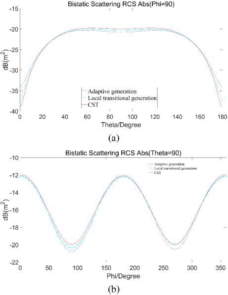
Figure 14: RCS of the cross-slot frequency selective surface simulated by FDTD based on two mesh generation methods and CST: (a) Phi90 and (b) Theta90.
Figure 14 shows that, compared with the adaptive mesh data, RCS based on local transition adaptive mesh data is in better agreement with the CST results.
Mesh quantity and FDTD simulation time obtained by different generation methods are shown in Table 2.
Table 2: Mesh quantity and simulation time of cross-slot frequency selective surface based on different generation methods
| Generation Method | Mesh Quantity | Simulation Time |
| Adaptive generation | 7620 | 18 min 49 s |
| Local transition generation |
16810 | 22 min 3 s |
| CST | 38808 | / |
Table 2 shows that, based on the adaptive mesh generation method, the proposed mesh generation method increases far less mesh quantity, which limits the ratio of all the adjacent meshes. Simulation time also increases by a small amount.
All the results of inverted-F antenna and cross-slot frequency selective surface verify from the side that the transition adaptive structured mesh generation method proposed in this paper has higher computational accuracy than the method proposed in [20].
In addition, in order to prove the accuracy of the mesh generation method proposed in this paper, we calculate the RCS of a metal sphere excited by plane wave. This sphere’s radius is 1 m. The plane wave propagates in the negative direction of the Z-axis and polarizes in the positive direction of the Y-axis. The simulation frequency is set to 0-0.4 GHz. Comparison between the FDTD simulation result based on the proposed generation method and Mie analytical result [21] is shown in Fig. 15. The comparison shows that the proposed generation method has good accuracy.
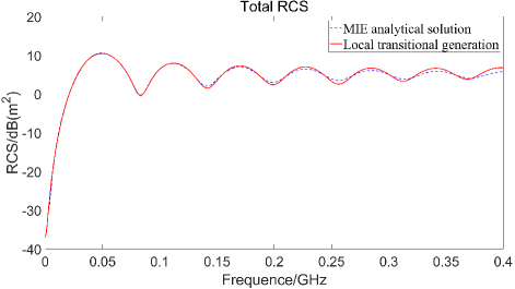
Figure 15: RCS of the sphere.
IV. CONCLUSION
In this paper, a new method of local transition adaptive structured mesh generation for FDTD simulation is proposed. By only adding transition meshes at media interfaces and boundaries, where the mesh sizes on both sides are significantly different, this method increases the simulation accuracy. Through FDTD simulation of inverted-F antenna and cross-slot frequency selective surface, it is found that the local transition adaptive mesh generation method can achieve considerable improvement in simulation accuracy at the cost of increasing a small number of meshes, compared with the adaptive mesh generation method. Compared with previous non-uniform mesh generation methods, this method could reduce mesh quantity and the complexity of mesh generation on the premise of ensuring simulation accuracy.
ACKNOWLEDGMENT
This work was supported by the National Key Research and Development Program of China (No. 2020YFA0709800) and supported by the National Natural Science Foundations of China (No. 62122061), and also supported by Stable-Support Scientific Project of China Research Institute of Radiowave Propagation (Grant No. A132303219).
REFERENCES
[1] K. Yee, “Numerical solution of initial boundary value problems involving maxwell’s equations in isotropic media,” IEEE Transactions on Antennas and Propagation, vol. 14, no. 3, pp. 302-307, May 1966.
[2] W. Sun, C. A. Balanis, M. P. Purchine, and G. Barber, “Three-dimensional automatic FDTD mesh generation on a PC,” in Proceedings of IEEE Antennas and Propagation Society International Symposium, Ann Arbor, MI, vol. 1, pp. 30-33, 1993.
[3] M. Yang and Y. Chen, “AutoMesh: An automatically adjustable, nonuniform, orthogonal FDTD mesh generator,” IEEE Antennas and Propagation Magazine, vol. 41, no. 2, pp. 13-19, Apr. 1999.
[4] A. Gheonjian and R. Jobava, “Non-uniform conforming mesh generator for FDTD scheme in 3D cylindrical coordinate system,” in DIPED - 2000. Proceedings of 5th International Seminar/Workshop on Direct and Inverse Problems of Electromagnetic and Acoustic Wave Theory, Tbilisi, Georgia, pp. 41-44, 2000.
[5] A. Taflove and S. C. Hagness, Computational Electrodynamics: The Finite-Difference Time-Domain Method. Norwood, MA: Artech House, pp. 473-483, 2000.
[6] G. Zhou, Y. Chen, and G. Shen, “Efficient non-uniform orthogonal mesh generation algorithm for cylindrical FDTD applications,” in IEEE Antennas and Propagation Society International Symposium. 2001 Digest. Held in conjunction with: USNC/URSI National Radio Science Meeting, Boston, MA, vol. 1, pp. 60-63, 2001.
[7] Y. Srisukh, J. Nehrbass, F. L. Teixeira, J.-F. Lee, and R. Lee, “An approach for automatic grid generation in three-dimensional FDTD simulations of complex geometries,” IEEE Antenna’s and Propagation Magazine, vol. 44, no. 4, pp. 75-80, Aug. 2002.
[8] K. Suzuki, T. Kashiwa, and Y. Hosoya, “Reducing the numerical dispersion in the FDTD analysis by modifying anisotropically the speed of light,” Electron. Commun. Jpn., vol. 85, no. 1, pt. 2, pp. 50-58, Jan. 2002.
[9] Y. Zhang, B.-Q. Gao, W. Ren, Z.-H. Xue, and W.-M. Li, “Analysis and application of new quasi-network characteristics of nonuniform mesh in FDTD simulation,” IEEE Transactions on Microwave Theory and Techniques, vol. 50, no. 11, pp. 2519-2526, Nov. 2002.
[10] S.-H. Sun and C. T. M. Choi, “Envelope ADI-FDTD method and its application in three-dimensional nonuniform meshes,” IEEE Microwave and Wireless Components Letters, vol. 17, no. 4, pp. 253-255, Apr. 2004.
[11] H. A. Fernandes, “Development of software for antenna analysis and design using FDTD,” master’s thesis, University of Lisbon, 2007.
[12] W. Yu and R. Mittra, “Electromagnetic scattering of underground object using nonuniform mesh FDTD and PML,” Microwave and Optical Technology Letters, vol. 21, no. 2, pp. 151-156, Apr.1999.
[13] W. Heinrich, P. M. Klaus Beilenhoff, and L. Roselli, “Optimum mesh grading for finite-difference method,” IEEE Trans. MTT, vol. 44, no. 9, pp. 1569-1574, Sep. 1996.
[14] G. Kim, E. Arvas, V. Demir, and A. Z. Elsherbeni, “A novel nonuniform subgridding scheme for FDTD using an optimal interpolation technique,” Progress in Electromagnetics Research B, vol. 44, pp. 137-161, 2012.
[15] H. Zhu, C. Gao, H.-L. Chen, Z.-H. Shi, and X.-H. Xu, “The research on FDTD mesh generation and visualization technology,” in 2012 6th Asia-Pacific Conference on Environmental Electromagnetics (CEEM), Shanghai, China, pp. 282-284, 2012.
[16] M. Berens, I. D. Flintoft, and J. F. Dawson, “Structured mesh generation: Open-source automatic nonuniform mesh generation for FDTD simulation,” IEEE Antennas and Propagation Magazine vol. 58, pp. 45-55, 2016.
[17] N. Feng, Y. Zhang, J. Zhu, Q. Zeng, and G. P. Wang, “High-accurate non-uniform grids for system-combined ADI-FDTD method in near-field scattering with proper CFL factor,” IEEE Access, vol. 9, pp. 18550-18559, 2021.
[18] X. Wang, G. Chen, S. Yang, Y. Li, W. Du, and D. Su, “An FCC-FDTD method on nonuniform grids with guaranteed stability for electromagnetic analysis,” IEEE Transactions on Antennas and Propagation, vol. 71, no. 12, pp. 9194-9206, Dec. 2023.
[19] Liang, Weibo, Y. Wu, Y. Zhang, M. Wang, C. Fan, H. Zheng, and E. Li, “Nonuniform grid single-field WCS FDTD method applied to multithread simulation of MIMO dielectric resonator antenna,” IEEE Antennas and Wireless Propagation Letters, vol. 22, no. 10, pp. 2487-2491, Oct. 2023.
[20] J. Chen, J. Guo, C. Mou, Z. Xu, and J. Wan, “A structured mesh generation based on improved ray-tracing method for finite difference time domain simulation,” Electronics, vol. 13, no. 7, p. 1189, 2024.
[21] J. M. Jin, Theory and Computation of Electromagnetic Fields. Hoboken, NJ: Wiley, 2010.
BIOGRAPHIES

Zixuan Cao was born in Zhangjiakou, China. He received the B.S. degree from Xi’an Jiaotong University, Xi’an, China, in 2023, in Information Engineering. He is currently studying for a master’s degree at Xi’an Jiaotong University, Xi’an, China. His research interests include adaptive non-uniform mesh generation method and adaptive sub-grid generation method for FDTDsimulation.

Chunhui Mou was born in Yantai, China. She received the B.S. and M.S. degrees from Xidian University, Xi’an, China, in 2012 and 2015, and the Ph.D. degree from Xi’an Jiaotong University, Xi’an, China, in 2023, all in electromagnetic field and microwave technology. She is currently working in Xi’an Jiaotong University, Xi’an, China, as a Postdoctoral Researcher. Her research interests include the fast FDTD method, FDTD mesh generation method and multi-physical field calculation.

Chenghao Wang was born in Shandong, China. He is currently a doctoral candidate at the School of Information and Communication Engineering of Xi’an Jiaotong University, majoring in Electromagnetic Field and Microwave Technology. He works at the China Research Institute of Radiowave Propagation (CRIRP), mainly focusing on research related to ground penetrating radar signal processing and other relevant work.

Juan Chen was born in Chongqing, China. She received the Ph.D. degree from Xi’an Jiaotong University, Xi’an, China, in 2008, in electromagnetic field and microwave technology. She is currently working in Xi’an Jiaotong University, Xi’an, China, as a professor. Her research interests include computational electromagnetics and microwave device design.

Shaolong Li was born in Ningxia, China. He received a master’s degree from the China Research Institute of Radiowave Propagation (CRIRP) in 2010 and has been working there ever since. He is mainly engaged in the research on radio frequency circuits such as pulsed transmitters and sampling receivers, as well as the research on ground penetrating radar antenna technology.
Cuirong Zhao was born in Jinan, Shandong Province, and graduated from Shanghai Jiao Tong University, China, in 1996, majoring in Detection Technology and Instruments. She is currently working at the China Research Institute of Radiowave Propagation (CRIRP) as a researcher. Her main research direction is the technology and application of ground penetrating radar.

Yuemeng Yin received the B.S. and M.S. degrees in electronic information from Northwestern Polytechnical University, Xi’an, China, in 2007 and 2010, respectively. He is currently a Senior Engineer with China Research Institute of Radiowave Propagation (CRIRP). His current research interests include target detection of underground and reconnaissance intelligence information processing.
ACES JOURNAL, Vol. 39, No. 11, 936–943
doi: 10.13052/2024.ACES.J.391101
© 2024 River Publishers