Design and Analysis of a Novel Vivaldi Antenna With Improved Gain for Fan Motion Detection in Smart Homes Using IR-UWB Radar
Ho-Gyun Yu and Sun-Woong Kim
1Department of Information and Communication Engineering
Chosun University, Gwangju, Republic of Korea
1030ghrbs@naver.com
2Center for Advanced Meta-Materials
Daejeon 34103, Republic of Korea
Corresponding author: woongskim1@naver.com
Submitted On: October 1, 2024; Accepted On: February 21, 2025
ABSTRACT
The proposed antenna is an ultra-wideband Vivaldi antenna optimized for impulse-radio ultra-wideband (IR-UWB) radar applications in smart home environments. Designed to detect indoor object motion, including fan movement, the antenna demonstrates enhanced directivity by integrating five semicircular slots and a polygonal structure in the radiating element. Fabricated on a TRF-45 substrate (dielectric constant of 4.5, loss tangent of 0.0035, thickness of 1.62 mm), the antenna exhibits an impedance bandwidth of approximately 2.28 GHz and achieves a maximum gain of 9.59 dBi at 8.5 GHz. The proposed design advances indoor motion detection capabilities for smart home applications by providing a compact, high-gain, and wideband antenna solution.
Index Terms: Impulse-radio ultra-wideband radar, smart home, Vivaldi antenna.
I. INTRODUCTION
By 2024, the number of single-person households in South Korea will exceed 10 million, and account for 41.8% of all households. This significant demographic shift has raised critical concerns about safety and energy efficiency. The ability to detect indoor emergencies and manage energy efficiently is becoming increasingly important for single-person households [1].
Smart home systems are able to control household appliances in real time and recognize human movement to quickly identify emergency situations. These systems increase the safety of single-person households and contribute to efficient energy use [2–4].
In smart home systems, accurate differentiation between people and objects is essential. This maximizes energy savings and prevents unnecessary energy consumption. The ability to differentiate between people and appliances such as fans contributes to the efficient operation of smart home systems [5].
Impulse-radio ultra-wideband (IR-UWB) radar uses ultra-wideband signals to detect subtle movements of both people and objects with high precision. This capability makes the UWB radar a promising technology for smart home systems and offers numerous potential applications [6–7].
In this paper, we propose an antenna with wide bandwidth, high gain, and high directivity, optimized for smart home applications. While typical UWB antennas have a bandwidth of 100-130%, the antenna presented in this study is specifically designed to maximize performance in selected frequency bands required through a practical IR-UWB radar system [8–9]. The IR-UWB radar module used in this research, IU-D-M-0.0 from Grit Custom IC, was experimentally tested in combination with the proposed antenna to validate its applicability in smart home environments. The module operates in key frequency bands of 7.7, 8.0, and 8.4 GHz, all of which are covered by the proposed antenna’s 6.25-8.53 GHz bandwidth [10]. Through this design, our study provides optimized performance for object detection in smart home applications and distinguishes itself from conventional UWB antennas.
Furthermore, this study holds unique value as it presents an object detection technology realized through an antenna design that achieves superior performance within selected frequency bands for smart home applications. The proposed antenna enables effective motion detection with its wide bandwidth and high gain, outperforming typical UWB antennas, and demonstrates potential to enhance energy management and safety in smart home systems. Our tailored antenna design addresses potential frequency range challenges in smart home environments. Through experimental validation, we establish its practical applicability in smart home scenarios, with contributions toward improved accuracy and efficiency in object detection for future smart home systems.
Accordingly, in this paper the design and structure of the proposed antenna is discussed in section II and the measurement results to validate its performance are presented in section III. Finally, section IV describes the application of the antenna in an IR-UWB radar system to evaluate its potential for smart home applications. The objective of this study was to demonstrate that the proposed antenna can contribute to efficient and reliable motion detection in smart home systems.
II. ANTENNA DESIGN
A. Antenna geometry
The geometry of the proposed Vivaldi antenna for the IR-UWB radar is shown in Fig. 1. Vivaldi antennas radiate radio waves in the z-axis direction through a slot that tapers into a triangular structure. These radiating elements are located on the top layer. To supply the radiating element of the antenna with a radio wave signal, an input source was also fed through a microstrip line located on the bottom layer.
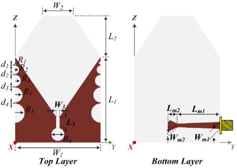
Figure 1: Geometry of the proposed Vivaldi antenna for IR-UWB radar.
To increase the gain, five semicircular slots and a polygon structure were added to the radiating element on the top layer and aperture of the edge. The proposed Vivaldi antenna was fabricated on a TRF-45 substrate with a dielectric constant of 4.5, loss tangent of 0.0035, and thickness of 1.62 mm. The design parameters of the proposed antenna follow.
The fundamental gain of the proposed antenna is determined by design parameters L and W, and the radiating element slot of the antenna tapers linearly to a triangular structure from W to W. However, to achieve a higher antenna gain, five semicircular slots with different radii (R-R) and polygonal structures (L and W) are designed. Finally, the design parameters for the microstrip line are L, W, and W. The proposed Vivaldi antenna was designed using HFSS, and the design parameters are as follows: L50 mm, W50 mm, L21.65 mm, W22.70 mm, L8.4 mm,W1.5 mm, R=1 mm, R2 mm, R3 mm, R4 mm, R5 mm, R3 mm, d=1 mm, d 1 mm, d1 mm, d 1 mm, L25.5 mm, W3 mm, L3 mm, and W1 mm.
B. Antenna analysis
To explain the design process of the proposed Vivaldi antenna, it was designed using three main design methods. The designs are shown in Fig. 2. The proposed antenna was designed using a conventional Vivaldi antenna, as shown in Fig. 2 (a). A conventional Vivaldi antenna is characterized by end-fire radiation, which concentrates radio waves and signals in one direction. However, depending on the application, it may be necessary to further improve the directivity and gain of the antenna to concentrate the signal in a specific direction. To improve the directivity and gain of the antenna, five semicircular slots and a polygon structure were added to the conventional Vivaldi antenna, as shown in Figs. 2 (b) and (c).
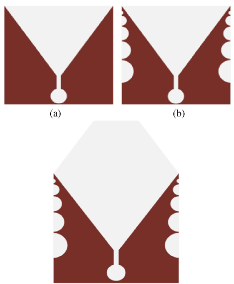
Figure 2: Schematic design of the proposed Vivaldi antenna: (a) conventional Vivaldi antenna, (b) Vivaldi antenna with five circular slots, and (c) final design of proposed Vivaldi antenna.
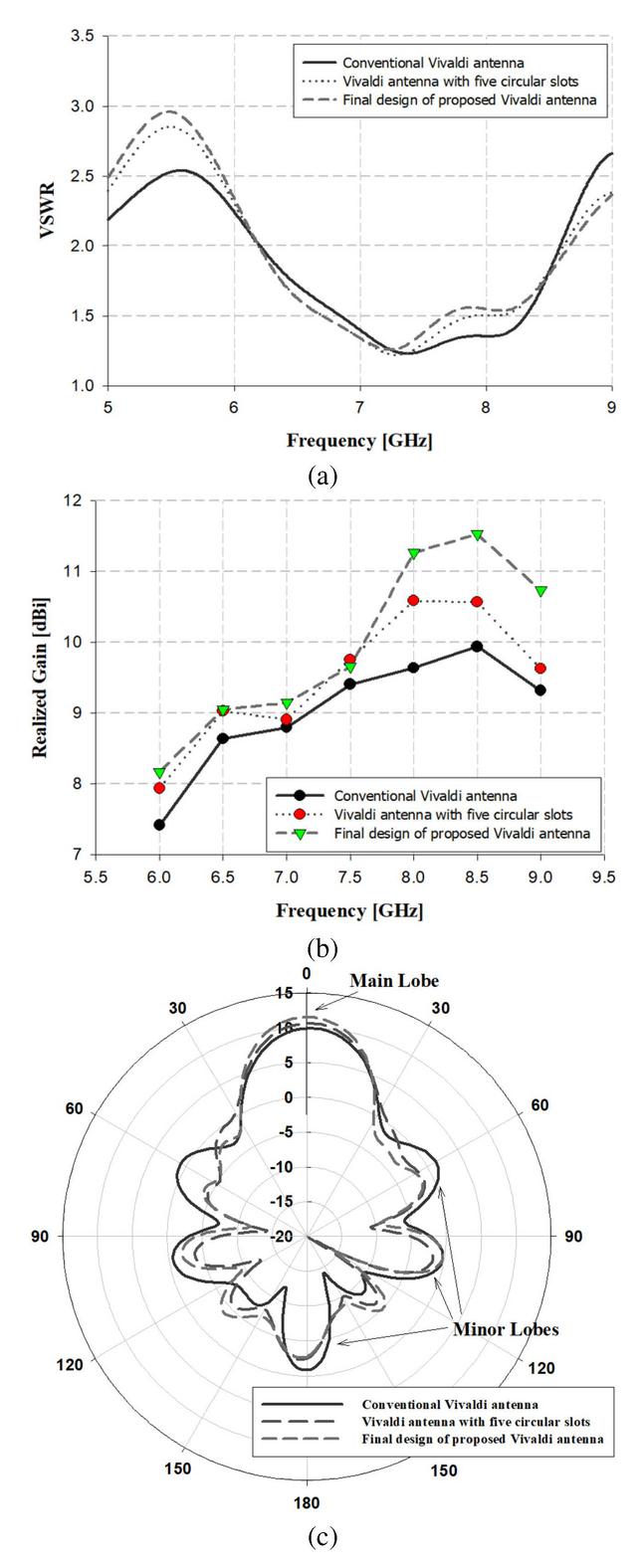
Figure 3: Simulation results of three configurations for the Vivaldi antenna: (a) VSWR, (b) realized gain, and (c) radiation pattern in the 8.5 GHz band.
For the design of the proposed Vivaldi antenna, simulations were conducted with the results presented in Fig. 3. As shown in Fig. 3 (a), the VSWR characteristics for each design were compared. The conventional Vivaldi antenna achieved a bandwidth of 2.27 GHz in the 6.28-8.55 GHz range with VSWR2, while the Vivaldi antenna with five circular slots showed an improved bandwidth of 2.43 GHz within the 6.19-8.61 GHz range.
The final design of the proposed Vivaldi antenna achieved the widest bandwidth, covering 2.46 GHz in the 6.20-8.66 GHz range, demonstrating enhanced performance over previous designs. As shown in Fig. 3 (b), the realized gain simulation results indicate that the final design of the Vivaldi antenna improves gain across the bandwidth. The conventional Vivaldi antenna achieved a maximum gain of 9.94 dBi at 8.5 GHz, while the Vivaldi antenna with five circular slots reached 10.67 dBi at 8.85 GHz. The final design of the proposed antenna recorded the highest gain of 11.53 dBi at 8.85 GHz. Figure 3 (c) illustrates the radiation pattern for the 8.5 GHz band, showing that the radiation characteristics of the proposed antenna are enhanced, primarily in the main lobe.
The enhancement of the main lobe in the proposed antenna can be attributed to the addition of five circular slots and polygonal structures, which contribute to optimizing the antenna’s directivity. These structural modifications adjust the current distribution on the radiating surface, increasing the gain of the main lobe while reducing the size of the side lobes, thereby improving the overall directivity. In other words, the circular slots and polygonal structures focus the radiated energy into the main lobe and suppress unnecessary side lobes, resulting in a more defined radiation pattern. The final design of the proposed Vivaldi antenna was suppressed to below 0 dBi in the minor lobes, except for the main lobe, and the main lobe was improved by more than 10 dBi. The simulation results for the three design methods are listed in Table 1.
Table 1: Comparison of the simulation results for the design methods
| Frequency(GHz) | Simulation Results of the Realized Gain (dBi) | ||
| Conventional Vivaldi Antenna |
Vivaldi Antenna with Five Circular Slots |
Proposed Vivaldi Antenna | |
| 6 | 7.42 | 7.94 | 8.17 |
| 6.5 | 8.64 | 9.03 | 9.05 |
| 7 | 8.80 | 8.91 | 9.15 |
| 7.5 | 9.41 | 9.76 | 9.66 |
| 8 | 9.64 | 10.59 | 11.27 |
| 8.5 | 9.94 | 10.57 | 11.53 |
| 9 | 9.32 | 9.63 | 10.74 |
The proposed Vivaldi antenna shows an improved realized gain across the entire frequency range compared to the conventional Vivaldi antenna and the Vivaldi antenna with five circular slots. Notably, it achieves a maximum gain of 11.27 dBi at 8 GHz and 11.53 dBi at 8.5 GHz, demonstrating superior radiation characteristics overall.
To explain the radiation mechanism of the proposed Vivaldi antenna, a surface-current simulation was performed for the E-field, as shown in Fig. 4.
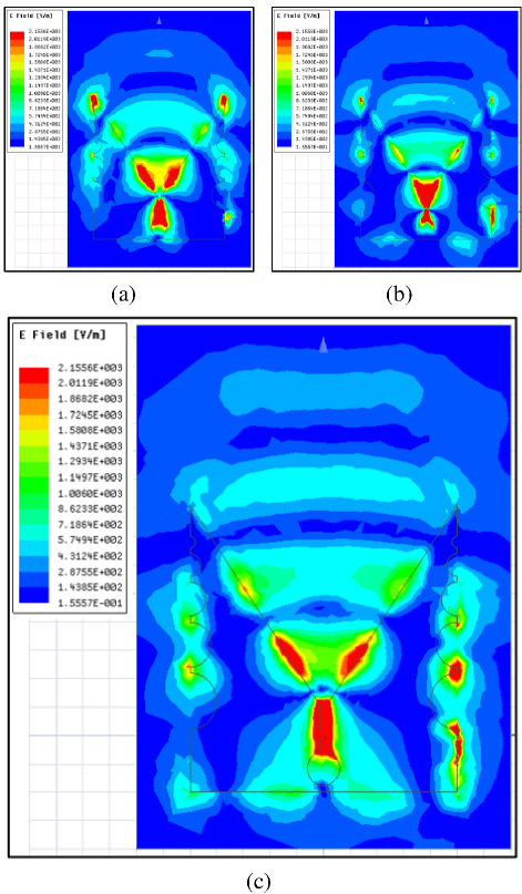
Figure 4: Simulation analysis of the surface current distribution for the proposed Vivaldi antenna: (a) 6.5 GHz, (b) 7.5 GHz, and (c) 8.5 GHz.
As shown in Fig. 4, the Vivaldi antenna exhibits a current distribution along the length of its tapered slot. This current extends to the termination of the slot, leading to the emission of radiation along the z-axis. At different frequencies, this current induces the generation of wavelengths resulting in the directional radiation properties observed at the open end of the antenna. These radiated waves were directed with precision to the intended transmission orientation within the planned radarsystem.
III. RESULTS AND DISCUSSION OF THE ANTENNA
A. Experimental environment
The proposed Vivaldi antenna was fabricated to verify the design, and the measurement results were obtained using a variety of instruments. A photograph of the fabricated Vivaldi antenna is shown in Fig. 5.
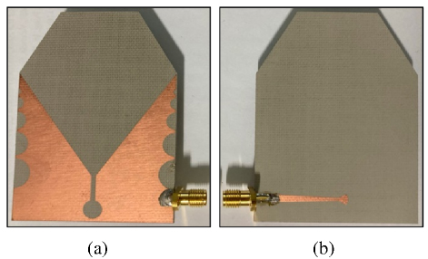
Figure 5: Photograph of the fabricated Vivaldi antenna: (a) top layer and (b) bottom layer.
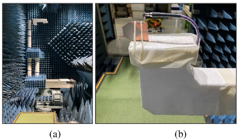
Figure 6: Measurement configuration: (a) experimental environment-1 and (b) experimental environment-2.
The gain and radiation pattern of the fabricated Vivaldi antenna were measured using a large antenna measurement system. The measurement results within the proposed bandwidth were obtained with a Tx antenna in a far-field anechoic chamber. The experimental environment is shown in Fig. 6.
B. Measurement results
To obtain the VSWR results, the fabricated Vivaldi antenna was measured using a vector network analyzer (E8361A, Agilent Co.). The VSWR results for the fabricated Vivaldi antenna are shown in Fig. 7.
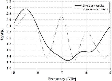
Figure 7: VSWR results of the fabricated Vivaldi antenna.
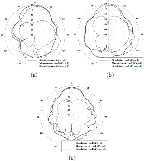
Figure 8: 2D radiation pattern results for the E-plane (YZ-plane) of the fabricated Vivaldi antenna: (a) 6.5 GHz, (b) 7.5 GHz, and (c) 8.5 GHz.
As shown in Fig. 7, the simulated VSWR result of the fabricated Vivaldi antenna was satisfied by VSWR2 at 6.25-8.53 GHz, resulting in an impedance bandwidth of 2.28 GHz. In contrast, the measurement results showed some discrepancies from the simulation results. The measurement results were included in the impedance bandwidth of the simulation, but the 7 GHz and 8 GHz bands were somewhat suppressed. However, this should not be a major problem in the proposed application. This will be demonstrated in the nextsection.
The simulation and measurement results for the 2D radiation pattern were analyzed in the E-plane (YZ plane) and H-plane (XZ plane), as shown in Figs. 8and 9.
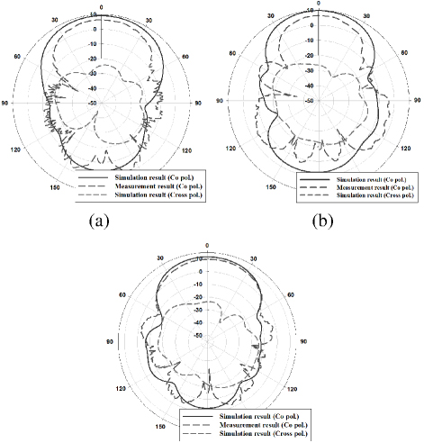
Figure 9: 2D radiation pattern results for the H-plane (XZ-plane) of the fabricated Vivaldi antenna: (a) 6.5 GHz, (b) 7.5 GHz, and (c) 8.5 GHz.
As shown in Figs. 8 and 9, the 2D radiation patterns of the fabricated Vivaldi antenna were analyzed for the directional radiation pattern, in which the waves were concentrated in both the E- and H-planes in the Z direction. The 3 dB beamwidth (HPBW: half power beam width) of the simulation and measurement results for the E-plane are 45 and 38 at 6.5 GHz, 35 and 41 at 7.5 GHz, and 30 and 34 at 8.5 GHz. For the simulation and measurement results, the H-plane is 74 and 58 at 6.5 GHz, 60 and 45 at 7.5 GHz, and 59 and 60 at 8.5 GHz. In addition, the simulation and measurement results for the maximum gain are 9.05 dBi and 7.07 dBi at 6.5 GHz, 9.66 dBi and 7.24 dBi at 7.5 GHz, and 11.53 dBi and 9.59 dBi at 8.5 GHz. Furthermore, the simulated cross-polarized radiation pattern showed attenuated radiation characteristics in both the E- and H-planes compared to the main radiation direction, which complements the directional characteristics and contributes to enhancing the antenna’s performance.
A noticeable difference is observed between the simulation and measurement results, which can be attributed to a few factors. First, as the antenna was fabricated using an etching process, minor inaccuracies may have arisen during fabrication. The etching process could have caused a dimensional variation of a few millimeters, potentially affecting the measurement results. Second, there may be unaccounted losses between the antenna and the measurement cable. Despite this noticeable discrepancy, the proposed antenna’s practicality was verified by successfully integrating it with an actual IR-UWB radar system.
In this study, existing studies were compared with the proposed antenna to analyze its performance.
Table 2: Performance comparison between existing wideband antenna designs and the proposed antenna
| Ref. | Antenna Type | Frequency Range (GHz) | Gain(dBi) | Application |
| [11] | Vivaldi | 4.00-8.00 | 8.3 | Through-wall radar |
| [12] | Bowtie | 0.34-0.77 | 9.2 | Ground penetrating radar |
| [13] | Vivaldi | 0.47-1.00 | 2.57 | UHF DVB-T/T2 |
| [14] | Patch | 7.1-7.9 | 8.4 | IR-UWB radar |
| [15] | Vivaldi | 660-15 | 15 | Concealed object detection |
| [16] | Bowtie | 0.31-0.93 | 9.3 | Ground penetrating radar |
| [17] | Vivaldi | 2.42-11.52 | 8.61 | Medical imaging |
| Proposed Antenna | Vivaldi | 6.25-8.53 | 9.59 | Smart home system |
Table 2 presents a performance comparison of different types of wideband antennas, including bowtie, patch, and Vivaldi antennas. These antennas are widely used in different fields because of their high gain and wide bandwidth. The proposed Vivaldi antenna operates in the frequency range of 6.25-8.53 GHz with a gain of 9.59 dBi, demonstrating its potential for smart home system applications.
IV. EXPERIMENTAL STUDY AND RESULTS
A. Setup and configuration of the radar
As shown in Fig. 10, a test setup was established to verify the performance of the fabricated antenna. The radar module used for the fan motion detection experiment was an IU-D-M-0.0 from GRIT Customs IC Inc. In this experiment, the radar module consists of a transmitter and a receiver. The transmitted UWB signal is reflected off the rotating fan blades and received by the receiver. The radar records amplitude variations in the reflected signal over time, frame by frame, to analyze changes in the signal caused by the rotation of the fan blades. This allows the radar system to detect the motion of the fan blades, and the measured data is used to determine the positional variations and rotation cycle of the fan.
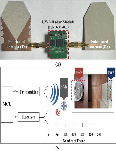
Figure 10: Testing setup for the fan motion detection experiment: (a) radar configuration and (b) fan motion detection setup.
Table 3: Specification for the experiment
| Parameter | Min | Typical | Max | Unit |
| Frequency range | 7.7 | 8.0 | 8.4 | GHz |
| Bandwidth | 1.7 | 1.9 | GHz | |
| EIRP | -45.7 | -44.0 | -43.1 | dBm/MHz |
| -17.9 | -16.0 | -14.7 | dBm/50 MHz | |
| Equivalent sampling rate | 20.48 | Gbps | ||
| Detection range | 0.1 | 15 | m |
The specifications of the IU-D-M-0.0 radar module, summarized in Table 3, were selected to optimize the detection of fan motion within the experimental setup [10]. These specifications enabled precise measurement and analysis of fan motion and ensured accurate performance evaluation of the fabricated antenna.
B. Signal processing and experimental results
As shown in Fig. 11, two important filters were applied to process the UWB radar data: clutter reduction and high-frequency noise reduction. These filters are critical for improving fan motion detection by suppressing clutter signals and emphasizing the relevant motion signals.
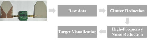
Figure 11: Block diagram of UWB radar signal processing.
In this study, the received signal consists of three components: the clutter signal , the target signal , and noise , as represented by the equation:
| (1) |
The clutter reduction step is designed to remove the static background noise (clutter) from the radar signal, which typically originates from stationary objects in the environment. This is done using a difference filter that calculates the difference between the current and previous signal samples. This approach emphasizes dynamic changes in the signal while suppressing static components such as clutter. The filter can be expressed in the z-domain as follows:
| (2) |
where is a filter coefficient that controls the rate of clutter attenuation. The numerator represents a high-pass characteristic that filters out low-frequency components associated with static clutter, while the denominator introduces an exponential moving average to smooth the signal [18–19]. After clutter reduction, the radar signal enters the high-frequency noise reduction phase, where a low-pass filter is applied to suppress high-frequency noise and preserve the low-frequency components associated with the fan’s movement. In the final stage of target visualization, the processed radar signals are converted into graphical representations to clearly depict the detected motion of the fan. Figure 12 illustrates the three stages of signal processing.
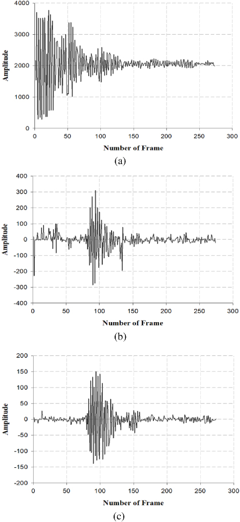
Figure 12: Results of signal processing: (a) raw radar data, (b) data after clutter reduction, and (c) data after high-frequency noise reduction.
In Fig. 12, the first result (a) shows the raw data in which the clutter signals dominate. After clutter reduction, the result (b) shows a cleaner signal with reduced noise. Finally, result (c) demonstrates the high-frequency noise-reduction phase, in which the signal is smoothed and only the essential motion signals are retained. Figure 13 illustrates the detection of the movement of the fan.
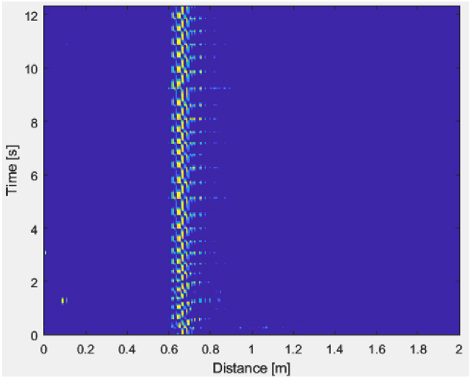
Figure 13: Detection of the movement of the fan.
As shown in Fig. 13, a periodic movement of the fan at a certain distance was detected using the time and distance axis. This result shows that the radar system successfully detected the movement of the fan.
V. CONCLUSION
In this study, a high-gain antenna capable of detecting indoor motion for smart home systems was proposed to meet the growing need for safety and energy efficient management in single-person households. The proposed antenna is characterized by a wide impedance bandwidth of 2.28 GHz in the frequency range of 6.25 to 8.53 GHz, a high gain of 9.59 dBi in the 8.5 GHz band, and excellent directivity characteristics. Based on these performance characteristics, the antenna was integrated into an IR-UWB radar module and successfully validated through experiments to detect the motion of objects, such as fans, in an indoor environment.
The contribution of this research lies in the successful demonstration of the applicability of the proposed antenna for precise motion detection and energy management in smart home systems. The wide bandwidth and high gain of the antenna provide the basis for improving the accuracy of motion detection in various applications and emphasize its importance as a component in future smart home configurations.
However, limitations of this study include the need for further miniaturization of the antenna and challenges in measuring fan rotation due to the low frame rate of the radar. Future research should focus on the development of low-profile antennas with improved resolution for IoT-based indoor occupancy detection and smart home systems. In addition, further experiments are needed on fan movement, human positioning, and biometric data measurement. These efforts pave the way for the integration of AI-based intelligent radar technologies and further expand the potential of the proposed system.
REFERENCES
[1] The Dong-A Ilbo, Single-person households reach 10 million in Korea [Online]. Available: https://www.donga.com/en/article/all/20240410/4871941/1#:~:text=10%2C%202024%2007%3A48.,all%20household%20types%20at%2041.8%2510April2024.
[2] A. Sanchez-Comas, K. Synnes, and J. Hallberg, “Hardware for recognition of human activities: A review of smart home and AAL related technologies,” Sensors, vol. 20, no. 15, pp. 1-26, July 2020.
[3] D. Bouchabou, S. M. Nguyen, C. Lohr, B. LeDuc, and I. Kanellos, “A survey of human activity recognition in smart homes based on IoT sensors algorithms: Taxonomies, challenges, and opportunities with deep learning,” Sensors, vol. 21, no. 18, pp. 1-28, Sep. 2021.
[4] G. Bhavanasi, L. Werthen-Brabants, T. Dhaene, and I. Couckuyt, “Patient activity recognition using radar sensors and machine learning,” Neural Computing and Applications, vol. 34, pp. 16033-16048, May 2022.
[5] M. Diyan, B. N. Silva, and K. Han, “A multi-objective approach for optimal energy management in smart home using the reinforcement learning,” Sensors, vol. 20, no. 12, pp. 1-20, June 2020.
[6] S. Klavestad, G. Assres, S. Fagernes, and T.-M. Gronli, ”Monitoring activities of daily living using UWB radar technology: A contactless approach,” IoT, vol. 1, no. 2, pp. 320-336, Oct. 2020.
[7] S. Singh, Q. Liang, D. Chen, and L. Sheng, ”Sense through wall human detection using UWB radar,” EURASIP Journal on Wireless Communications and Networking, vol. 2011, no. 20, pp. 1-11, June 2011.
[8] V. Portosi, A. M. Loconsole, A. Campana, F. Anelli, and F. Prudenzano, “A novel L-shaped metalens for ultra-wide band (UWB) antenna gain improvement,” Applied Sciences, vol. 13, no. 08, pp. 1-15, Apr. 2023.
[9] J. Ghimire and D. Y. Choi, “Ultra-wide band double-slot podal and antipodal Vivaldi antennas feed by compact out-of-phase power divider slot for fluid properties determination,” Sensors, vol. 22, no. 12, pp. 1-19, June 2022.
[10] GRIT Custom Integrated-Chip [Online]. Available: http://www.gritcic.com/ 12 Sep. 2024.
[11] J. Zhang, H. Lan, M. Li, and Y. Yang, “A handheld nano through-wall radar locating with the gain-enhanced Vivaldi antenna,” IEEE Sensors Journal, vol. 20, no. 05, pp. 4420-4429, Dec. 2019.
[12] Y. Li and J. Chen, “Design of miniaturized high gain bow-tie antenna,” IEEE Transactions on Antennas and Propagation, vol. 70, no. 01, pp. 738-743, Jan. 2022.
[13] N-R. Kwon, S-H. Ahn, and W-S. Lee, “Wideband printed antipodal Vivaldi antenna using straight slots for UHF DVB-T/T2 applications,” Applied Computational Electromagnetics Society (ACES) Journal, vol. 37, no. 06, pp. 726-732, June2022.
[14] V-T. Nguyen and J-Y. Chung, “Design of a planar antenna array with wide bandwidth and narrow beamwidth for IR-UWB radar applications,” Applied Sciences, vol. 12, no. 17, pp. 1-9, Aug. 2022.
[15] A. O. Asok, G. Nath S. J., and S. Dey, “Concealed object detection with microwave imaging using Vivaldi antennas utilizing novel time-domain beamforming algorithm,” IEEE Access, vol. 10, pp. 116987-117000, Nov. 2022.
[16] S. Pi, T. Wang, and J. Lin, “Directional and high-gain ultra-wideband bow-tie antenna for ground-penetrating radar applications,” Remote Sensing, vol. 15, no. 14, pp. 1-17, July 2023.
[17] S. Saleh, T. Saeidi, and N. Timmons, “Simple compact UWB Vivaldi antenna arrays for breast cancer detection,” Telecom, vol. 05, no. 02, pp. 312-332, Apr. 2024.
[18] A. Lazaro, A. Girbau, and R. Villarino, “Techniques for clutter suppression in the presence of body movements during the detection of respiratory activity through UWB radars,” Sensors, vol. 14, no. 02, pp. 2595-2618, Feb. 2014.
[19] S. Ahmed, D. Wang, J. Park, and S.-H. Cho, ”UWB-gestures, a public dataset of dynamic hand gestures acquired using impulse radar sensors,” Scientific Data, vol. 102, no. 08, pp. 1-9, Apr. 2021.
BIOGRAPHIES

Ho-Gyun Yu received his M.S. degree and completed his Ph.D. coursework from the Department of Information and Communication Engineering at Chosun University, Gwangju, South Korea, in 2019 and 2023, respectively. He is currently a Researcher at the Mechatronics Research Institute in Gwangju. His research interests include UWB antennas, UWB radar, and AI.

Sun-Woong Kim received his M.S. and Ph.D. degrees from the Department of Information and Communication Engineering at Chosun University, Gwangju, South Korea, in 2014 and 2018, respectively. He is currently a Researcher at the Center for Advanced Meta-Materials. His research interests include antennas, UWB antennas, IR-UWB radar, and metasurface antennas.
ACES JOURNAL, Vol. 40, No. 3, 203–211
doi: 10.13052/2025.ACES.J.400305
© 2025 River Publishers