Accelerated Variant Model-aided Optimization of Coupled Line Bandpass Filter
Ahmet Uluslu
Department of Electronics and Automation
Istanbul University-Cerrahpaşa, Istanbul 34500, Turkey
auluslu@iuc.edu.tr
Submitted On: October 16, 2024; Accepted On: December 15, 2024
ABSTRACT
Here, a 5-row microstrip coupled line filter design with six different variable design parameters having a center resonance frequency of 2.45 GHz is considered as a multi-dimensional and single-objective optimization problem using a variant of the newly proposed Chameleon swarm algorithm. In this study, three different objective functions specially adapted from mathematical models were used for the current problem. Additionally, artificial neural network (ANN) modeling support was used for acceleration, thus eliminating the extra hardware cost that may be needed. The filter toolbox, which was recently released with the MATLAB 2021b version, was used throughout the optimization process. The study includes multiple innovations, including the updated algorithm, new toolbox and original objective functions.
Index Terms: Chameleon swarm algorithm, coupled line bandpass filter, evolutionary algorithms, non-uniform microstrip filter, optimization techniques, swarm intelligence algorithms.
I. INTRODUCTION
Microwave filters are very important in RF and microwave applications. They combine or separate different frequencies from each other. Filters are frequently encountered in microwave systems, especially in satellite and mobile communication systems. The most sought-after features in these filter designs are high performance, low loss, small size and low cost. At the beginning of the usage areas of bandpass filters, we can offer devices such as oscillators and mixers to prevent unwanted signals. Many microwave systems, such as these devices, incorporate bandpass filter structures to block unwanted signals. In order to meet the requirements arising in this context, filters are designed as collective element and discrete element circuits. These designs consist of waveguide, coaxial line and microstrip transmission lines [1]. Microstrip parallel-connected filters consisting of microstrip transmission line are widely used in these designs because they have many advantages [2]. These parallel-connected microstrip filters used can create an unsymmetrical passband response as well as excess passband at multiples of the targeted frequency. The reason for the common harmonic’s formation in parallel connected microstrip filters is the difference in the phase velocities in the inhomogeneous dielectric medium in the microstrip structure. This causes performance degradation in systems such as frequency divider or WLAN receiver.
Combined microstrip lines are used in many circuit functions and the design procedures are well established [3, 4]. Principle application areas are directional combiners, filters and delay lines [5]. Parallel coupled line filters are generally used in microwave technologies at high frequencies (up to 0.8-30 GHz). At low- and mid-level frequencies, bandpass or filtering filters are generally in the form of distributed circuits and are used by combining classical resistors, coils and capacitors in different ways according to needs [6]. Resistors, coils and capacitors become an unstable and unsolvable material that encounters many problems as higher frequencies are increased. For this reason, at high frequencies, parallel combined line filters can be used as a solution with a completely different way of thinking and production without the need for conventional circuit elements. In microstrip structures, materials with different properties are combined on top of each other in different thickness, height and length, and these long strips are produced on the card surface in a straight, horizontal, perpendicular and parallel manner. The thickness of these strips, the distance between the strips, how long they will be and whether the strips will be connected to each other are decided during the design [7]. When the structure of the material used in the strips and the state of the layers are evaluated together with other components, it will answer questions such as what the center frequency, bandwidth and harmonics of the designed filter will be. As a result, since trouble-free filters cannot be designed with resistance coils and capacitors at high frequencies, fabricated to do their job, parallel combined line filters, which are stable at high frequencies and comply with the principles of materials science, are designed [8]. When two unshielded transmission lines are placed side by side, a proportion of the power available to the main line is coupled to the secondary line. Bandpass filters are indispensable elements of communication system designs. They reduce harmonics and spurious emissions for transmitters [9]. In coupled lines, the characteristic impedance can be increased [10] to widen the gaps and reduce coupling. Narrowing the line widths can cause an increase in conductor loss. Electromagnetic field analysis or experimental measurements may be needed to find the distance to be left between the resonators [11]. However, the design equations of the stepped track structure are only correct for the central frequency of the passband and further optimization with CAD tools is still required [12]. In brief, although there are methods that contain many empirical equations for filter designs, their complexity and inconsistency in some cases have led designers to filter simulation programs [13, 14].
Although there is a great interest in the design and optimization of microstrip combined line filters in the literature, there are many studies on it [15, 16]. In one study, circuit implementation of the filter was made through concentrated components such as inductors (L) and capacitors (C) for even and odd filter order. Afterwards, it was designed in a microstrip structure using mathematical equations and simulated with the help of the CST program. Both the inconsistency of the mathematical equations and the complexity of the method have made the design very difficult [17]. In another study, microstrip coupled line bandpass filter design with 400 MHz bandwidth has been made. Since this study is based on mathematical equations, it has computational complexity as well as computational redundancy [18]. In another study, a method for optimizing the coupling gaps for a microstrip bandpass filter design using cross-linked resonators to achieve high selectivity is presented [19]. PSO was used as the algorithm. The optimization process is based on mathematical equations. In addition, many filter design optimization studies have been done [20–23]. However, many of them perform the validation simulation for a single model by optimizing from numerical calculations.
In recent years, scientists have developed many optimization methods based on different methods in order to overcome multi-dimensional and various optimization problems, in engineering science as well as other fields. In this context, there are several optimization studies on transistors that form the basis of microwave electronics [24–27]. Optimization problems contain single- or multi-objective problems that need to be improved. The mathematical expression of these problems is called the objective function. In addition, these objective functions are combined within themselves and include the cost function. In most problems, the objective functions and design variables are linear. Nonlinear objective functions, on the other hand, have limitations due to their complex structure [28]. Often, nonlinear problems contain sharp and multiple peaks along with many local optima [28]. It may be necessary to generate complex objective functions for optimization problems with complex and large design parameters. The main purpose of optimization is to achieve the global optimum. Meta-heuristic algorithms are very successful in both preventing the local optimum and finding the global optimum. For this reason, studies are carried out on new meta-heuristic algorithm models. One of them is the Chameleon swarm algorithm (CSA), which has been discussed recently. Chameleons are mostly creatures that live in forests or deserts and are constantly searching for food. There was no optimization algorithm in the literature that mimicked the behavior of chameleons in nature, until [29]. In this study, a meta-heuristic algorithm called CSA is presented to solve global optimization problems [29]. The inspiration for this algorithm is the dynamic behavior of chameleons looking for food in nature. In another study on this successful study, developed with existing CSA variant models, supported by original complex linear and nonlinear objective functions, variant models played an active role in finding more performance results [28].
In order to overcome the traditional filter design problems mentioned previously, the complexities and inconsistencies in filter designs suggest that the optimization problem of bandpass filter design can be overcome by using the newly proposed variant CSA. The fact that both the bandwidth and the center resonance frequency can be easily adjusted by changing only the objective function with optimization is a step towards solving traditional problems. In addition, the fact that there is no empirical equation, and the system is simulation-based is an advantage over other studies in terms of closeness to reality. In addition, the large number of filter design parameters and the fact that the filter is bandpass make the problem difficult. In order to overcome this power optimization design problem, the variant CSA supplemented with the original objective functions will be used. There are many bandpass filter studies in the literature, and almost none of them solved by the optimization method are simulation-based. The filter toolbox of MATLAB 2021, which has just been put into use with the 2021b version, saves us from computational confusion. In addition, no filter optimization studies have yet been encountered with the algorithm or its derivatives used.
This article is organized as follows. Filter design is mentioned in section II. In section III, information about the objective and cost functions used together with the variant optimization used is given. The study part is in section IV, and self-criticism is in section V. The paper concludes with section VI.
II. FILTER DESIGN
Microstrip transmission lines are the most widely used transmission lines in microwave engineering and applications. Discussing the advantages and disadvantages of microstrip transmission lines, the fact that the circuit is on a patch allows it to easily adapt to the surface on which it is applied. We can add ease of production and low cost as another advantage. If we talk about the disadvantages, its high insulation can cause radiation and undesired filter response. Also, although the microstrip supports transverse electromagnetic mode (TEM) due to the fill factor, in some cases it may appear non-TEM due to the interconnection of the lines. Therefore, we can classify the frequency of the microstrip bandpass filter as asymmetric [30]. The dielectric constant of the substrate is greater than the effective dielectric constant because some parts of the transmission line are in air. Therefore, dielectric constants are important for microstrip lines. There are many studies on microstrip coupled line filter design [31, 32]. In particular, microstrip line Chebyshev single band and dual bandpass filters are widely available [33–35]. There are also many bandpass filter designs made with different approaches [33–35].
Here, a bandpass filter with a middle band of 2.45 GHz with a microstrip combined line filter structure will be designed. The proposed filter consists of the supply connected to the parallel lines connected between the two ports. In the proposed design, the characteristic impedance is chosen as Z 50 , while the microstrip bandpass is designed on Teflon material with =4.4 and the combined line filter height h 1.6 mm from the ground plane. Figure 1 shows the schematic of the filter design. The design parameter values specified in the diagram are given in Table 1 in detail. Of the eight design parameters specified here, six of them are variable and two of them are fixed values. In addition, three of the variable design parameters contain six different variable parameters. In the design processes, PEC was chosen as the conductor and Teflon as the substrate. Although there are many empirical equations and methods for microstrip coupled line filter design, it has been mentioned that the equations are not suitable for practical designs due to their inconsistency and the technique is old [13–14]. For this reason, the filter toolbox of MATLAB 2021, which is one of the toolboxes that are libraries of MATLAB functions adapted to MATLAB for the solution of special problems in optimization operations and filter simulations in the study, was used. A toolbox in Simulink is
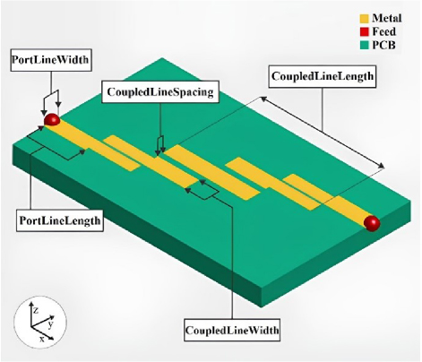
Figure 1: Coupled line filter.
Table 1: Coupled line filter design parameters
| Parameter | Definition | Center Value | Value Range |
| FilterOrder | Filter order | 5 | - |
| PortLineLength | Length of input and output lines | 27.9 (mm) | 40% |
| PortLineWidth | Width of input and output lines | 5.1 (mm) | 40% |
| CoupledLineLength | Lengths of coupled lines | [27.9 27.9 27.9 27.9 27.9 27.9] | 40% |
| CoupledLineWidth | Widths of coupled lines | [3.6 4.9 4.9 4.9 4.9 3.6] | 40% |
| CoupledLineSpacing | Distance between coupled lines | [0.1827 1.9 1.9 1.9 1.9 0.1827] | 40% |
| Height | Height of coupled line filter from ground plane | 1.6 (mm) | constant |
| GroundPlaneWidth | Width of ground plane | 55.1 (mm) | 40% |
| Substrate | Type of dielectric material | Teflon | - |
| Conductor | Type of metal used in conducting layers | PEC | - |
Design problems are getting more difficult day by day and designers’ demand for better solutions makes existing optimization algorithms insufficient and directs researchers to develop new algorithms. Meta-heuristic algorithms work by integrating them into real simulations to mimic some properties of commodities existing in nature [36]. One of the algorithms that has been developed in recent years and inspired by nature is CSA. This algorithm supports the concept of ‘no-free-lunch’ (NFL) [29]. Chameleons usually live-in forests or deserts and constantly search for food. A study published a few years ago found an optimization algorithm that mimics the behavior of chameleons in nature [29]. Essentially, the algorithm adapts the movements chameleons make while searching for food to the mathematical model. One part of this is that chameleons catch their prey by rapidly throwing their tongues. When all these behaviors are applied to create an optimization algorithm, a model that finds suitable solutions is obtained. The mentioned CSA algorithm is an algorithm that has proven its success in global optimization problems. In addition, it is seen that more successful results are obtained in the study compared to other meta-heuristic algorithms such as GA, GWO and PSO [29].
The source of inspiration of CSA consists of briefly following the prey, pursuing the prey with its eyes and attacking the prey [28]. To summarize the functions of the algorithm used:
Initialization and function evaluation: Since CSA is a population-based algorithm, this stage covers the beginning of the process.
Search for prey: Covers the updating of the behavior and movements of the chameleons while searching for food.
Rotation of the chameleon eyes: Chameleons have the ability to determine the location of their prey by using the ability to rotate their eyes independently of each other.
Prey hunting: When chameleons are very close to their prey, they attack and conclude the hunting process. We can say that the chameleon that comes closest to its prey is the best and is assumed to be optimal.
In another study, a U-slot antenna design with four resonance frequencies has been discussed as a multi-dimensional and single-objective optimization problem by using CSA and its variants developed in collaboration with CSA, proposed in [28]. It has been suggested that the CSA and its variants can undoubtedly be adapted to any optimization problem with a large number of variable design parameters [28]. The mCSA algorithm produced will be used in the study.
A. Variants of CSA
Reproduction, crossover and mutation are among the most frequently used operators in many population-based optimization algorithms, especially genetic-based optimization algorithms. It is made possible by these basic processes for the previous generation to transfer their characteristics to new generations. Thus, individuals with good characteristics are more likely to be selected for breeding. Considering all these advantages, mutation and crossover operators that were not found in the original CSA were added to the basic CSA and a variant model was derived [28].
Crossover and mutation are two basic operators used in genetic algorithms to create new individuals from existing individuals. The crossover operator is used to generate two new individuals (children) through information exchange (gene swap) from two individuals (parents) in the current population. The purpose of crossover is to combine good parts of old chromosomes to produce new individuals that are expected to be better. The frequency of crossover is controlled by a parameter called crossover probability. A high crossover rate will cause the search space to be explored very quickly, and individuals that are better than others will deteriorate very quickly after new breeding processes. A low crossover rate will cause very few new and different individuals to enter the new generation resulting from reproduction, and the research space will not be adequately scanned. Therefore, determining a reasonable probability value for the crossover rate is important for the performance of the algorithm. Major crossover operators are single-point crossover, two-point crossover and PMX. According to the two-point crossover, the two points to be crossed over in the chromosomes are determined and these parts are exchanged to obtain two new generation chromosomes. Other genes are inherited from the first parent to the first progeny chromosome, respectively. In the same way, transfer is made from the second parent to the second new generation chromosome. During the transfer, if the transferred gene is already present in the new chromosome, the other gene is passed on. If not, this gene is transferred to the new chromosome. In the study, the two-point crossover operator is preferred.
The mutation operator, on the other hand, simulates the genetic mutation event in nature and plays an important role in the success of GA. This operator generates a new solution by changing the value of some genes of the chromosomes of an existing solution. The mutation operator provides scanning of different regions of the solution space by inserting new information into the existing population. In this way, it helps to overcome the problem of early convergence. In a genetic algorithm without a mutation operator, the optimal solution can only be obtained if the necessary information is found in the initial population. Therefore, the population size of the genetic algorithm without a mutation operator will have to be kept very large. This will reduce the speed of the algorithm. The genes to be mutated are randomly determined according to a very small mutation rate. A high mutation rate will introduce excessive randomness to the search and accelerate divergence. Conversely, a low mutation rate will slow divergence and prevent full exploration of the search space. Therefore, the problem of early convergence will arise. Three types of mutation operators have been studied. These are the ’Swap’, ’Insert’ and ’Shift’ mutation operators. The swap operator swaps two randomly determined genes on a randomly determined chromosome. In the study, the ’Swap’ operator was preferred.
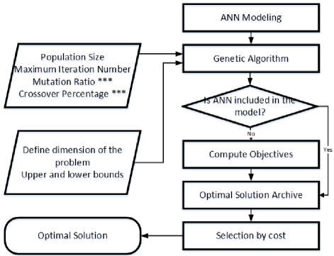
Figure 2: Flowchart for optimal solution of CSA with accelerated variant model support of the coupled line bandpass filter.
First, a cut-off point was created between the results found. The algorithm was forced to find the desired results because the costs were shown high in the results that were outside the desired limit. After the calculation of the targets, artificial neural network (ANN) modeling should be added before the solution archive is created. This can shorten the optimization time by reducing the number of iterations to reach the minimum cost value. In addition, all the results found in each step were brought together to form a feasible solution set and this set was used for selection. Figure 2 shows its mathematical modeling. The beginning of the process is to define the parameters of the algorithm, such as the population size, maximum iterations and weight coefficients, as shown in Fig. 2. At this point, the latest development, ANN model support, was specified externally. Thus, the optimization time was shortened by up to six times. As seen in Fig. 2, if the ANN model is included, the calculation part is skipped, and time is saved. All this ends when the best solution is reached.
B. Objective and cost functions
The variant model of the CSA, which is a new optimization technique, will be supported with original objective functions in order to obtain more performance results. Here, three different types of objective function pairs are defined for the pass and stop band segments adapted from linear and nonlinear mathematical models. These were named in a study as polynomial, power and exponential model, respectively [28]. Two measurement functions, S and S, were chosen as the decision variables that make up these unique objective functions. Here, it is aimed that S should be as small as possible (maximum -10 dB) in the passband, and S should be close to 0 in the passing band, and S should be as small as possible (maximum -10 dB) and S should be close to 0 in the stopping band. Since S and S have the same importance for this problem, the weighting coefficients of the measurement functions (wc 0.5) are taken as equal.
Adapted from the polynomial model, the objective function pairs are defined as follows for two separate parts, the bandpass and the bandstop. Bandpass part:
| (1) |
| (2) |
Bandstop part:
| (3) |
| (4) |
The objective function pairs adapted from the power model are defined as follows for two separate parts, the bandpass and the bandstop. Bandpass part:
| (5) |
| (6) |
Bandstop part:
| (7) |
| (8) |
Adapted from the exponential model, the objective function pairs are defined for two separate parts, the bandpass and the bandstop. Bandpass part:
| (9) |
| (10) |
Bandstop part:
| (11) | ||||
| (12) |
where i=2.44 and 2.46, j=2.36 and 2.54. Each represent a resonance cutoff frequency.
In addition to all these objective functions, a cost function has been determined. It is found as a result of the collection of the objective function pairs determined for the pass and stop band parts and is defined as follows:
| (13) |
In the next section, a detailed working case will be presented on the optimization of the combined line filter with the predetermined design parameters for the bandpass model with a center frequency of 2.45 GHz.
IV. RESULTS
In the analysis part of the study, the variant model of the CSA, which was previously proposed in a study and has proven its success against other traditional algorithms, will be used in the optimization problem of the bandpass combined line filter design with a center frequency of 2.45 GHz. As is known, changing the length and width of the lines will cause different results of the S parameters. In the study, firstly, the analysis of the cases with and without ANN added to show the effect of ANN support on the study was made. Then, the most optimal algorithm parameters will be selected for the problem. Finally, experiments will be made with equal weight functions for three different original objective function pairs adapted based on the mathematical models with the selected optimal algorithm parameters.
A. Performance analysis of ANN-aided modeling
Since the success of the proposed CSA against traditional algorithms was given in a recent study [28], no additional comparison was included in this study. Instead, since the optimization processes take a long time, ANN modeling support was used for acceleration, thus eliminating the extra hardware cost that may be needed. In this part of the study, experiments were carried out for different population values by choosing maximum iteration=30, which is parallel to the study in the literature. In order to see the difference in the graphs more clearly, the results are shown for two different cases, with and without ANN modeling support, for population (N)=60, which was found to be the most successful result and which we accepted as the default parameter, in the next part [28]. In Fig. 3, the typical cost and function evaluation number (FEN) change variations with the best performance repetition are shown. The best results from 10 different studies are selected and exhibited for both cases. With ANN modeling support, the step to reach the minimum cost was reduced from 30 to 25. Therefore, optimum was reached approximately 20% earlier. In addition, as shown in Fig. 3, ANN modeling and the archive section created with these models were included at the beginning of the application. As a result of skipping the calculation part of the objectives, it was seen that the application time was reduced by approximately six times.
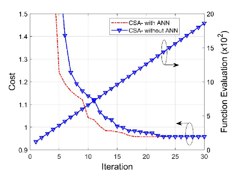
Figure 3: Typical cost and FEN variations with iteration of the best performance of CSA selected from 10 runs for optimization.
B. Optimal parameter set selection for optimization
Since CSA is a population-based algorithm, the selection of the population size is of great importance [29]. Considering both the possibility of being stuck in the local optimum and the waste of resources, this value should be chosen as the most optimum [37]. Performance comparisons were made over the cost (13) function by using OFp-OFp-OFs-OFs (1,2,3,4) among the objective function pairs determined with population (N)=30, 60 and 100 values in order for the study to be based on solid foundations. The results obtained are shown in Fig. 4 as typical variations of cost and FEN with the repetition of the best performance selected from 10 different studies. In addition, the cost and FEN variations in Fig. 4 are given in Table 2. Among the results obtained for this study, it is seen that the population (N) value which gives the result with the lowest minimum and average cost is 60.
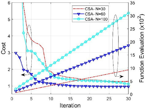
Figure 4: Typical cost and FEN variations with iteration of the best performance selected from among 10 runs based on population parameter selection.
Table 2: Performance evaluations of algorithm by population parameter for results in Fig. 4 (maximum iteration30)
| Population | Minimum | Maximum | Mean | |
| 30 | Cost | 1.262 | 10.815 | 2.583 |
| FEN | 750 | 60 | 930 | |
| 60 | Cost | 0.958 | 2.978 | 1.239 |
| FEN | 1500 | 120 | 1860 | |
| 100 | Cost | 1.113 | 10.174 | 2.170 |
| FEN | 2500 | 200 | 3100 |
C. Performances of different objective functions
The objective functions determined in the optimization process are primarily tried to converge to zero in proportion to their weight coefficients. For this reason, objective functions are critically important for an optimization problem. In this section, we have detailed mathematical calculations in the previous section in order to find S as small as possible (maximum -10 dB) in the bandpass part, and close to 0 in S, and as small as possible (-10 dB) in S in the bandstop part and close to 0 in S. Experiments were made using three different model objective function pairs adapted from the models. The best result obtained using OFp-OFp-OFs-OFs (1,2,3,4) is given in Fig. 5 as typical magnitude-frequency variation of S-S between 4 GHz and 5 GHz. Likewise, the most successful result obtained using OFp-OFp-OFs-OFs (5,6,7,8) is given in Fig. 6 as typical magnitude-frequency variation of S-S between 4 GHz and 5 GHz. Finally, the most successful result obtained using OFp-OFp-OFs-OFs (9,10,11,12) is given in Fig. 7 as typical magnitude-frequency variation of S-S between 4 GHz and 5 GHz. In addition, the design parameter values found as a result of this optimization are given numerically in Table 3. When all these results are considered together, it is seen that the most successful result with wider frequency bandwidth and better return loss is found by using OFp-OFp-OFs-OFs (5,6,7,8), which is called the Power Model.
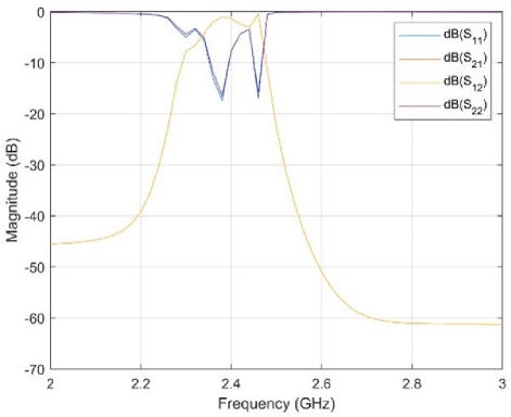
Figure 5: S parameters of the bandpass filter obtained using MATLAB with the polynomial model objective function.
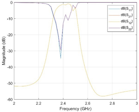
Figure 6: S parameters of the bandpass filter obtained using MATLAB with the power model objective function.
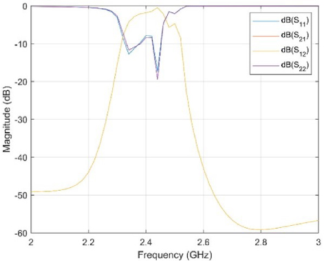
Figure 7: S parameters of the bandpass filter obtained using MATLAB with the exponential model objective function.
Table 3: Performance evaluations of algorithm by population parameter for results in Figs. 5–7 (maximum iteration=30)
| Parameter | Polynomial Model Value (mm) | Power Model Value (mm) | Exponential Model Value (mm) |
| Port Line Length | 17.47 | 34.21 | 27.81 |
| Port Line Width | 4.25 | 4.78 | 4.92 |
| Coupled Line Length | [22.7 22.7 22.7 22.7 22.7 22.7] | [22.28 22.28 22.28 22.28 22.28 22.28] | [22.28 22.28 22.28 22.28 22.28 22.28] |
| Coupled Line Width | [2.36 4.85 4.85 4.85 4.85 2.36] | [3.79 5.01 5.01 5.01 5.01 3.79] | [3.24 5.1 5.1 5.1 5.1 3.24] |
| Coupled Line Spacing | [0.24 2.29 2.29 2.29 2.29 0.24] | [0.12 2.29 2.29 2.29 2.29 0.12] | [0.16 2.13 2.13 2.13 2.13 0.16] |
| Ground Plane Width | 54.97 | 54.34 | 46.98 |
V. DISCUSSION
At the beginning of the study, modeling support was not added because the optimization processes were short for a computer with powerful hardware. Since the optimization processes became undesirably long with additional trials, the flow of the study was directed to modeling-supported optimization. A much longer model (8-9 rows) could have been preferred from an architectural perspective. However, this would only extend the processes, and it would be unknown whether it would have any effect on the verification of the successful implementation. In future studies, it is possible to make the processes faster by changing the network used in modeling support. A suggested approach for longer-lasting models such as antenna optimization can also be tried.
VI. CONCLUSION
In this study, a new variant CSA in the literature of a combined line filter with a center frequency of 2.45 GHz, three of which contain six different variable parameters in themselves, in total eight design parameters, is considered as a multi-dimensional and single-objective optimization problem. The study started with the performance measurements of the modeling-supported shortening of the optimization processes. Then, it continued with the selection of the optimum population parameter considering both the possibility of getting stuck in the local optimum and the waste of resources. The linear and nonlinear objective functions used in the study are completely original and have been specially designed for the bandpass filter model, one of the mathematical models. Although the CSA model preferred in the study is a very new optimization algorithm, it has not yet been encountered in any filter design optimization problem in the literature. In addition, the variant model used played an active role in finding more performance results in another study [28]. The study aimed to find the optimum filter design dimensions. In all these selections, objective function pairs played an active role as well as algorithm parameters. Compared to other results, the most successful result with wider frequency bandwidth and better return loss was obtained using OFp-OFp-OFs-OFs (5,6,7,8) adapted from the power model. The study discussed includes many innovations with all these aspects and sheds light on future studies. It shows that this algorithm, which can overcome the problems of filter designers, can be a safe, practical and efficient solution for multi-dimensional optimization applications. Henceforth, CSA can undoubtedly be adapted by changing the objective functions for any optimization problem with a large number of design parameters.
REFERENCES
[1] A. Uluslu, “Microstrip Low Pass Filter Analysis and Design,” in Research & Reviews in Engineering- Gece Kitaplğ Yaynevi, Gece Kitaplğ Yaynevi, 2021.
[2] J. Hong and M. J. Lancaster, Microstrip Filters for RF/Microwave Applications. Hoboken, NJ: Wiley, 2001.
[3] S. B. Cohn, “Parallel-coupled transmission-line-resonator filters,” IEEE Trans Microw Theory Tech, vol. 6, no. 2, pp. 223-231, Apr. 1958.
[4] G. L. Matthaei, “Design of wide-band (and narrow-band) band-pass microwave filters on the insertion loss basis,” IEEE Trans. Microw. Theory Tech., vol. 8, no. 6, pp. 580-593, Nov. 1960.
[5] S. S. Olokede and B. S. Paul, “Design of a narrow-band microstrip ring resonator bandpass filter,” in 2017 Progress In Electromagnetics Research Symposium - Spring (PIERS), pp. 1835-1841, May 2017.
[6] L. Zhu, S. Sun, and R. Li, Microwave Bandpass Filters for Wideband Communications, vol. 20. Hoboken, NJ: Wiley, 2012.
[7] C.-S. Ye, Y.-K. Su, M.-H. Weng, C.-Y. Hung, and R.-Y. Yang, “Design of the compact parallel-coupled lines wideband bandpass filters using image parameter method,” Progress In Electromagnetics Research, vol. 100, pp. 153-173,2010.
[8] M. Makimoto and S. Yamashita, “Bandpass filters using parallel coupled stripline stepped impedance resonators,” IEEE Trans. Microw. Theory Tech., vol. 28, no. 12, pp. 1413-1417, Dec. 1980.
[9] C. J. Kikkert, “A design technique for microstrip filters,” in 2008 2nd International Conference on Signal Processing and Communication Systems, pp. 1-5, Dec. 2008.
[10] D. Ahn, C.-S. Kim, M.-H. Chung, D.-H. Lee, D. W. Lew, and H. J. Hong, “The design of parallel coupled line filter with arbitrary image impedance,” in 1998 IEEE MTT-S International Microwave Symposium Digest, pp. 909-912,1998.
[11] E. G. Cristal, “Tapped-line coupled transmission lines with applications to interdigital and combline filters,” IEEE Trans. Microw. Theory Tech., vol. 23, no. 12, pp. 1007-1012, Dec. 1975.
[12] K. W. Kim, C.-H. Park, and S.-J. Han, “A new design procedure of tapped coupled-line filters,” in IEEE Antennas and Propagation Society Symposium, pp. 2863-2866, 2004.
[13] J. Ossorio, J. Vague, V. E. Boria, and M. Guglielmi, “Exploring the tunability range of classic circular waveguide dual mode filters using EM-based CAD,” in 2017 IEEE MTT-S International Conference on Numerical Electromagnetic and Multiphysics Modeling and Optimization for RF, Microwave, and Terahertz Applications (NEMO), pp. 332-334, May 2017.
[14] G. Mansour, M. K. A. Rahim, and H. A. Aldeeb, “Cross-coupled microstrip bandpass filters with finite frequency transmission zeros,” in 2021 IEEE 1st International Maghreb Meeting of the Conference on Sciences and Techniques of Automatic Control and Computer Engineering MI-STA, pp. 684-688, May 2021.
[15] T. Mahouti, T. Yldrm, and N. Kuşkonmaz, “Artificial intelligence-based design optimization of nonuniform microstrip line band pass filter,” International Journal of Numerical Modelling: Electronic Networks, Devices and Fields, vol. 34, no. 6, Nov. 2021.
[16] A. Uluslu, “Design of microstrip filter by modeling with reduced data,” Applied Computational Electromagnetics Society (ACES) Journal, vol. 36, no. 11, pp. 1453-1459, Dec. 2021.
[17] T. Ragani, N. A. Touhami, and M. Agoutane, “Designing a microstrip coupled line bandpass filter,” International Journal of Engineering & Technology, vol. 2, no. 4, p. 266, Sep. 2013.
[18] M. Sasic and S. T. Imeci, “Design of microstrip coupled-line bandpass filter,” Heritage and Sustainable Development, vol. 3, no. 1, pp. 44-52, Apr. 2021.
[19] S. Vikash, K. Natarajan, B. Sri Hari, B. Sri Pragathi, T. Poornima, and S. Natarajamani, “Multi-objective optimization of cross coupled resonators based microstrip bandpass filter using PSO,” in 2020 5th International Conference on Communication and Electronics Systems (ICCES), pp. 322-325, June 2020.
[20] H. Oraizi and N. Azadi-Tinat, “A novel method for the design and optimization of microstrip multi-section bandpass combline filters,” in 2006 European Microwave Conference, pp. 1217-1220, Sep. 2006.
[21] T. Singh, J. Chacko, N. Sebastian, R. Thoppilan, A. Kotrashetti, and S. Mande, “Design and optimization of microstrip hairpin-line bandpass filter using DOE methodology,” in 2012 International Conference on Communication, Information & Computing Technology (ICCICT), pp. 1-6, Oct. 2012.
[22] E. V. Navin Baaskar, R. Harshini, T. Poornima, and S. Natarajamani, “Design of microstrip bandpass filter based on genetic optimization,” in 2019 International Conference on Communication and Electronics Systems (ICCES), pp. 1237-1239, July 2019.
[23] V. A. Karpova and N. V. Ivanov, “Optimization of a microstrip tunable bandpass filter design,” in 2021 IEEE Conference of Russian Young Researchers in Electrical and Electronic Engineering (ElConRus), pp. 129-132, Jan. 2021.
[24] F. Gunes, A. Uluslu, and P. Mahouti, “Pareto optimal characterization of a microwave transistor,” IEEE Access, vol. 8, pp. 47900-47913, 2020.
[25] F. Kiani, A. Seyyedabbasi, and P. Mahouti, “Optimal characterization of a microwave transistor using grey wolf algorithms,” Analog Integr Circuits Signal Process, vol. 109, no. 3, pp. 599-609, Dec. 2021.
[26] F. Güneş, S. Demirel, and P. Mahouti, “Design of a front-end amplifier for the maximum power delivery and required noise by HBMO with support vector microstrip model,” Radioengineering, vol. 23, no. 1, pp. 134-143, 2014.
[27] F. Güneş, S. Demirel, and P. Mahouti, “A simple and efficient honey bee mating optimization approach to performance characterization of a microwave transistor for the maximum power delivery and required noise,” International Journal of Numerical Modelling: Electronic Networks, Devices and Fields, vol. 29, no. 1, pp. 4-20, Jan. 2016.
[28] A. Uluslu, “Chameleon swarm algorithm assisted optimization of U-slot patch antenna for quad-band applications,” IEEE Access, vol. 10, pp. 74152-74163, 2022.
[29] M. S. Braik, “Chameleon swarm algorithm: A bio-inspired optimizer for solving engineering design problems,” Expert Syst. Appl., vol. 174, p. 114685, July 2021.
[30] I. J. Bahl and D. K. Trivedi, “A designer’s guide to microstrip line,” Microwaves, vol. 16, pp. 174-182, May 1977.
[31] X. Wu, Y. Li, and X. Liu, “High-order dual-port quasi-absorptive microstrip coupled-line bandpass filters,” IEEE Trans. Microw. Theory Tech., vol. 68, no. 4, pp. 1462-1475, Apr. 2020.
[32] S. Chatterjee, T. K. Das, and B. Gupta, “Harmonic suppression in in-line parallel-coupled microstrip bandpass filter by Minkowski fractals,” in 2017 Mediterranean Microwave Symposium (MMS), pp. 1-4, Nov. 2017.
[33] S. R. Choudhury, A. Sengupta, and S. Das, “Bandpass filters using multilayered microstrip structures,” in 2018 Emerging Trends in Electronic Devices and Computational Techniques (EDCT), pp. 1-3, Mar. 2018.
[34] R. A. Rahim, S. I. S. Hassan, M. N. Junita, and N. A. M. Damrah, “Microstrip dual-band bandpass filter for ISM band applications,” in 2015 IEEE International Conference on Control System, Computing and Engineering (ICCSCE), pp. 281-286, Nov. 2015.
[35] M. B. Priya, K. Ramprakash, P. Pavithra, and D. A. Joe, “A cost effective dual band Chebyshev parallel coupled microstrip line bandpass filter for ISM band applications,” in 2017 International Conference on Wireless Communications, Signal Processing and Networking (WiSPNET), pp. 623-626, Mar. 2017.
[36] M. Jain, V. Singh, and A. Rani, “A novel nature-inspired algorithm for optimization: Squirrel search algorithm,” Swarm Evol. Comput., vol. 44, pp. 148-175, Feb. 2019.
[37] C. R. Reeves and J. E. Rowe, Genetic Algorithms—Principles and Perspectives, vol. 20. Boston, MA: Springer US, 2002.
BIOGRAPHIES

Ahmet Uluslu received his Ph.D. from Istanbul Yıldız Technical University Electronics and Communication Engineering Department in 2020. He completed his master’s degree at the Department of Electromagnetic Fields and Microwave Techniques from the same university. He is working as an associate professor at Istanbul University - Cerrahpaşa Electronics and Automation Department. His current research areas are microwave circuits, especially optimization techniques of microwave circuits, antenna design optimization-modelling, surrogate-based optimization and artificial intelligence algorithm applications.
ACES JOURNAL, Vol. 39, No. 12, 1082–1091
doi: 10.13052/2024.ACES.J.391207
© 2024 River Publishers