A Compact High Scanning Rate Leaky-Wave Antenna Based on Spoof Surface Plasmon Polaritons Transmission Line
Xiaoyan Zhang1, 2, Siyuan Yu1, Aiyun Zhan1, and Yan Mei1
1School of Information and Software Engineering East China Jiaotong University, Nanchang 330013, China
xy_zhang3129@ecjtu.edu.cn, 1577397340@qq.com, 707290432@qq.com, 360291931@qq.com
2State Key Laboratory of Millimeter Waves Nanjing, China
Submitted On: October 24, 2024
Accepted On: May 29, 2025
ABSTRACT
A leaky-wave antenna with wide scanning angle and high scanning rate based on spoof surface plasmon polaritons transmission line (SSPPs-TL) is proposed. A tilted unit structure is introduced to flexibly adjust the dispersion characteristics, which not only reduces the cut-off frequency of the antenna but also enhances the electric field confinement. In addition, in order to achieve faster beam scanning, a row of periodic metal patches are placed on one side of the SSPPs slow wave structure, while periodic modulation metal strips are introduced on the other side. The proposed design converts slow waves into fast waves while broadening the scanning angle, thereby increasing the scanning rate. The effectiveness of the proposed scheme has been verified by the designed SSPP leaky-wave antenna in this paper. The measured results demonstrate that the designed antenna achieves a total scanning range of 41∘ to 30∘ and a maximum gain of 9.31 dBi in the operating frequency band of 5.8–8.4 GHz. Moreover, this antenna features a low profile and a compact structure and can be applied in communication systems.
Keywords: Asymmetric transmission structure, beam scanning, high scanning rate, leaky-wave antenna, spoof surface plasmon polaritons (SSPPs)..
1 INTRODUCTION
In recent years, leaky-wave antennas [1] have received extensive attention due to their characteristics, including frequency beam scanning, strong directivity, compact structure and low cost. Compared with traditional array antennas [2], leaky-wave antennas do not require a complex feed network or a large number of array elements to control beam scanning. Therefore, they offer significant advantages, such as light weight, small size, and low cost, making them highly suitable for radar sensors and wireless communication systems [3].
The radiation of leaky-wave antennas is typically generated by the gradual leakage of electromagnetic energy along the structure [4, 5, 6]. These structures can be categorized into two types: uniform leaky-wave antennas [7, 8] and periodic leaky-wave antennas [9]. Uniform leaky-wave antennas are usually designed based on patch array structures, which results in a large longitudinal size. In contrast, periodic leaky-wave antennas do not rely on antenna arrays and can excite radiation modes solely through the transmission structure of periodic sine modulation. However, they have the disadvantage of large horizontal dimensions. To address the limitations of leaky-wave antenna structures, various methods have been introduced into the design in recent years, including Goubau lines [10], composite right/left-handed metamaterial transmission line [11], substrate integrated waveguide [12, 13] and spoof surface plasmon polaritons transmission lines (SSPPs-TLs) [14, 15, 16]. An SSPPs-TL can emulate the optical properties of surface plasmon polaritons (SPPs) at microwave frequencies, exhibiting characteristics such as short wavelength, field focusing, and strong dispersion. Thus, it has become an important structure for facilitating the design of beamforming antennas.
In the early stages of SSPP antenna research, wider beam scanning angles attracted more attention. For example, in 2016, Yin et al. designed a patch-type SSPP leaky-wave antenna operating at 3–6 GHz with a scanning angle of 55∘ [17]. In 2017, Guan et al. extended the scanning angle to 66∘ by enhancing the coupling strength of the SSPP antenna with a double-layer structure [18]. In 2018, a 16 GHz bandwidth was utilized to achieve a remarkable 90∘ scanning range [19]. However, the above designs face similar problems of a large size or a low scanning efficiency (because of the large frequency band). Since then, the study of compact SSPP antennas with narrow bandwidths and relatively wide scanning angles has attracted increasing interest. In 2018, an SSPP antenna by loading periodic sinusoidal modulation strips was proposed. Its bandwidth was only 2 GHz, but its scanning range reached from 30∘ to 51∘ [20]. However, its size remained relatively large . In 2019, a similar technique was used to reduce the size of an SSPP antenna to with a scanning angle of 64.6 ∘ and a bandwidth of 4.5 GHz [21]. The reason for the low scanning rates of SSPP antennas is that most of their structures are periodic, which may result in the Bragg effect. Bragg resonance can significantly reduce radiation efficiency and may even completely suppress electromagnetic wave radiation. This phenomenon is referred to as open stopband (OSB). In 2024, an impedance-discontinuous SSPP periodic structure was introduced to suppress OSB, which enables the antenna to achieve a scanning angle of 84∘ while maintaining a relatively small size and bandwidth (5 GHz) [22]. In summary, the primary challenge for SSPP antennas lies in balancing a narrow bandwidth and a compact size while achieving a wide scanning angle.
In this paper, a wide-angle high scanning rate SSPP antenna is proposed. The tilted straight strips are utilized as the periodic structure of the SSPPs-TL, which can reduce the lateral size of the antenna, lower the cutoff frequency, and enhance the electric field bonding ability. On one side of the SSPPs-TL, radiation patches are introduced to leak electromagnetic energy from the SSPPs-TL into free space, while on the other side, periodic modulation metal ripples are introduced to form an asymmetric SSPPs transmission structure. The asymmetric structure disrupts the Bragg reflection condition and reduce the energy reflection, thus weakening the influence of the OSB, expanding the scanning range of the antenna and improving its scanning rate, which is crucial for spectrum conservation and improving frequency band utilization efficiency, as it can cause continuous beam angle changes within a limited spectral range, reduce the directional dwell time of the beam, and thus reduce the probability of signal interference through spatiotemporal signal distribution.
2 DESIGN CONFIGURATION AND APPROACH
2.1 Overall design of the antenna
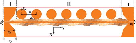
Figure 1 Overall structure of the proposed SSPPs leaky-wave antenna.
The overall structure of the proposed antenna is illustrated in Fig. 1. It has a size of mm2. The substrate of the antenna is an F4B dielectric with a thickness of 0.8 mm and a relative dielectric constant of 2.25 (loss tangent of 0.001). The coppers on the substrate have a thickness of 0.035 mm. This antenna consists of two parts: I and II. Part I comprises a coplanar waveguide and two transition structures at both ends, which are designed for impedance matching between the coplanar waveguide and the SSPPs-TL. Part II consists of double-sided asymmetric SSPPs strips and seven equidistant circular metal radiation patches. These asymmetric periodic strips effectively suppress sidelobes and enhance wide-edge radiation. Furthermore, to enhance the gain of the leaky-wave antenna, the height of the strips is gradually increased by . Utilizing this method effectively lowers the cut-off frequency of SSPPs-TL, thereby enabling a tighter confinement of electromagnetic energy. Subsequently, when radiation patches are incorporated, a greater amount of energy is coupled into the radiation and subsequently radiated into free space, which leads to an enhanced gain. Ultimately, the electromagnetic waves propagate in parts I and II and radiate into free space by coupling with radiation patches.
2.2 Design of SSPPs-TL
The structures of the SSPPs-TL are shown in Fig. 2. To reduce the longitudinal size of the antenna, tilted unit structures are employed. The metal strips on the upper and lower sides of the transmission line exhibit distinct configurations. Except for the ones used for impedance matching at both ends, the strips on the upper side of the transmission line are evenly distributed in parallel, while the others on the lower side exhibit periodic wave like distribution characteristics.
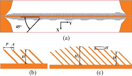
Figure 2 Structures of the SSPPs-TL: (a) overall structure, (b) unit structures on the upper and (c) lower side of SSPPs-TL.
The dispersion characteristics of the metal strips shown in Fig. 2 (c) are given in Fig. 3. The data is obtained using the CST Microwave Studio’s eigenmode solver. The variation in wave number defined as
| (1) |
is observed. Here, is the frequency of the leaky wave and is its phase velocity. The relationship between and the parameters of the strips is
| (2) |
where is the wave number in free space, and represent the width and period of the strips (see Fig. 2), respectively. Generally, is much smaller than . Therefore, is critical. Increasing will shorten the wavelength, thereby tightly binding the electromagnetic waves to the surface of SSPPs units. According to equation (2), only when can be obtained. Therefore, in the range of 9 GHz, the theoretical value of is less than 3.87 mm. In this case, the phase velocity of the electromagnetic wave on the surface of SSPP satisfies , which is a slow wave.
To verify the above analysis, is initially set to 3 mm, and the tilt angles () of the metal strips are changed from 30∘ to 90∘. As Fig. 3 (a) shows, as decreases, the dispersion curve approaches to the light values at 45∘ and 30∘. Because a small tilt angle will increase the overall lateral size of the antenna, is chosen in this paper. Then, and are set to 0.3 mm and 1.44 mm, respectively; is changed from 2.4 mm to 3 mm and 3.6 mm, with a scanning frequency range of 0–25 GHz. From the data in Fig. 3 (b), we can see that, at the same frequency, as increases, becomes larger, and the corresponding of the leaky wave decreases, causing the dispersion curve to deviate from light. In addition, in the scanning frequency band of 10 GHz, as increases, the of electromagnetic waves changes smoothly, seemingly confined to the range of 10 GHz. All of the above phenomena indicate that the fundamental mode of the SSPP waveguide is located in the slow wave region. As increases, the leakage wave field will be more tightly combined with the SSPPs units and cannot be directly radiated into space.
By periodically loading metal circular patches on the SSPPs-TL, spatial harmonics can be introduced to radiate electromagnetic energy. According to the leaky-wave antenna theory, the main beam radiation direction of the SSPP antenna is determined by [10]
| (3) |
where is the propagation constant of the spatial harmonic, which is defined as
| (4) |
is the modulation period of the patches. According to equations (1) and (4), once changes, also changes, which in turn adjusts to achieve a phase control, allowing the SSPP antenna to achieve continuous scanning of the beam from back to end over a wide-angle range.
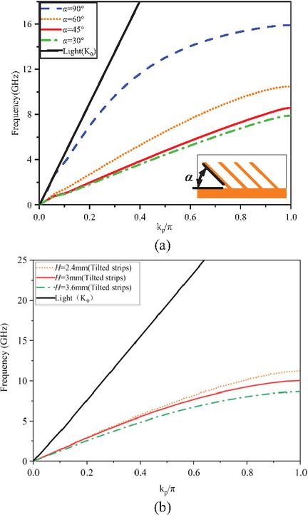
Figure 3 Dispersion characteristics of the SSPPs-TLs constructed from metal strips with (a) tilt angles and (b) different heights.
Figures 4 (a) and (b) depict the SSPPs-TLs’ electric field intensity distributions at different frequencies. The data indicate that the cut-off frequency of the SSPPs-TLs is 10 GHz. When the operating frequency (6–9 GHz), the electric fields near the SSPPs-TLs are tightly bound, which can effectively transfer electromagnetic energy from port 1 to port 2. When the frequency , the electric field gradually weakens. Comparing the electric field intensity distribution characteristics of Figs. 4 (a) and (b), it is evident that the asymmetric structure of SSPPs-TLs provides stronger confinement to electromagnetic waves.
Figure 4 (c) illustrates the electric field intensity distribution after the addition of seven metal circular patches on the upper side of the SSPPs-TL. On the one hand, the patches guide the electric field intensity confined on both sides of SSPP-TL to the edge of the patches and radiate into free space. On the other hand, the introduction of metal patches further improves the impedance matching of the SSPPs-TL and expands its bandwidth, as shown in Fig. 6. As shown in Fig. 6 (b), when the number of patches increases from 3 to 7, the impedance matching at 9–9.5 GHz becomes better.
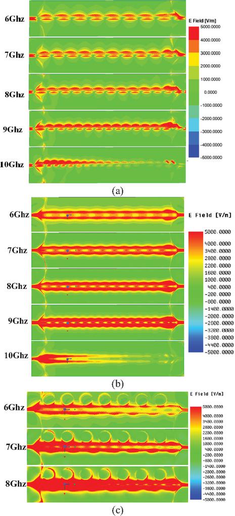
Figure 4 Electric field intensity distribution diagram of the SSPPs-TLs with (a) symmetric structures, (b) asymmetric structures at GHz and (c) circular metal patches at GHz.
The reflection coefficients shown in Fig. 6 exhibit ripples, and similar phenomena are commonly observed in the reflection coefficient of SSPP antennas [11, 13]. The reason may be that the SSPP structure is composed of many unit slots, resulting in the generation of many resonance points.
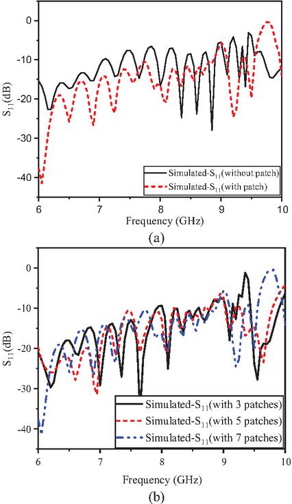
Figure 5 Comparison of values of SSPPs-TLs in the following situations: (a) with and without patches and (b) the number of patches has increased from 3 to 7.
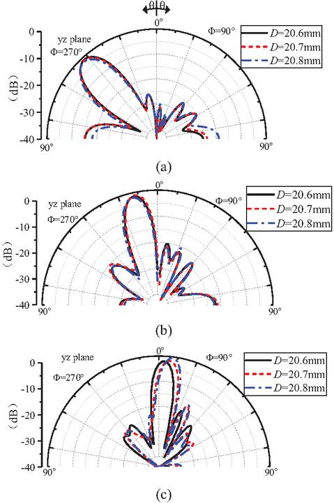
Figure 6 Radiation patterns at different values of at (a) GHz, (b) 7.4 GHz and (c) 8.8 GHz.
In order to radiate the electromagnetic energy of leaky waves, equidistant circular metal patches are introduced to interfere with the transmission characteristics of SSPPs waveguides. According to Fig. 3, when GHz, the guided wavelength of SSPPs-TL is 13.8 mm. Therefore, the radius of each circular patch is set to , and the patch spacing is mm [17]. Figure 6 compares the changes in SSPP antenna patterns when changes from 20.6 to 20.8 mm. Obviously, 20.7 mm is not an optimal value. When GHz with mm, the directional patterns of the SSPP antenna shows a significant rightward rotation.
Figure 7 shows the effect of changing the values of the unit slot on the antenna. The data shows that when GHz and 8.6 GHz, the beam angle of mm and 0.3 mm is almost the same as that of mm, with no significant change; but when GHz, the beam angle of mm significantly rotates to the right, showing obvious beam scanning characteristics.
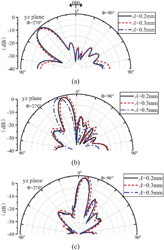
Figure 7 Radiation patterns at different values of at (a) GHz, (b) 7.6 GHz and (c) 8.6 GHz.
As shown in Fig. 8, at 6.2 GHz, the influence of parameter from 1.43 mm to 1.45 mm on the radiation pattern is not significant.
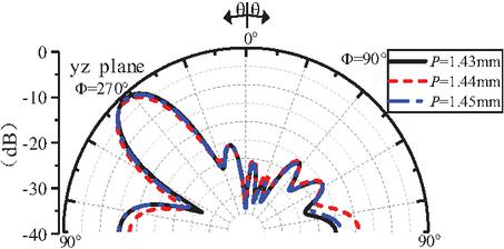
Figure 8 Radiation pattern at different values of at 6.2 GHz.
After optimization, the parameters of the SSPP antenna are shown in Table 1.
Table 1 Optimized parameters
| Parameter | Value (mm) | Parameter | Value (mm) |
| 1.8 | 1.44 | ||
| 0.5 | 3 | ||
| 17.5 | 4.2 | ||
| 14.5 | 0.3 | ||
| 7 | |||
| 20.8 | |||
| 0.3 | |||
| 0.3 |
3 MEASURED RESULTS AND DISCUSSION
The proposed SSPP leaky-wave antenna is fabricated and tested (see Fig. 9). As shown in Fig. 9 (a), two ports are connected to the SMA connector, one end is fed and the other end is connected to a 50-ohm matching load. The radiation characteristics such as radiation pattern and gain of the fabricated antenna prototype are measured by microwave anechoic chamber (see Figs. 9 (b) and (c)).
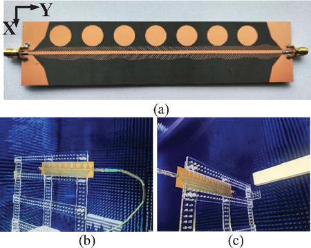
Figure 9 Physical images and testing environment: (a) antenna physical photo; (b) and (c) testing environment in an anechoic chamber.
An Agilent Network Analyzer (Keysight E5071C) is used to measure the -parameters of the antenna. The simulated and measured reflection coefficients are compared and shown in Fig. 10. It can be seen that they match well. The test results show that the amplitude of the reflection coefficient in the range of 5–10 GHz is less than 10 dB, indicating that the antenna achieves good impedance matching and energy transmission in the working frequency range. However, due to the compact and dense structures of the proposed SSPP leaky-wave antenna, the losses caused by fabrication tolerance are very significant. Moreover, radiation loss, dielectric loss, or conductor loss are not considered in simulation, which lead to the measured being significantly lower than the simulated ones.
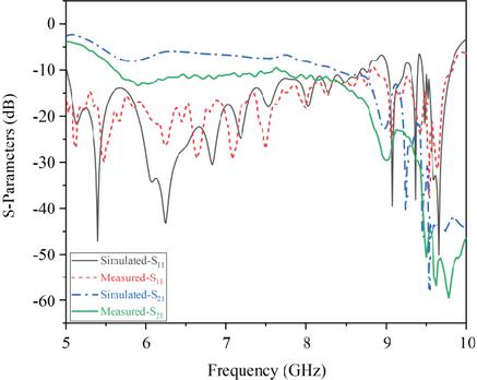
Figure 10 Comparisons of -parameters between simulation and measurement of the proposed SSPP antenna.
The simulated and measured radiation patterns of the designed antenna at different frequencies are shown in Fig. 11. Specifically, it can be seen from the diagram that the scanning angle of the symmetrical structure only reaches 56∘ in the 2.8 GHz frequency band. After the introduction of asymmetric structure, the main beam scans from front to back as the frequency increases in the operating frequency band. The simulated scanning angle range is to and the tested scanning angle range is 41∘ to 30∘ (). Although the angle is slightly offset, the simulation and measurement results are basically consistent.
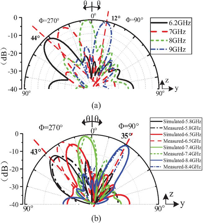
Figure 11 Comparison of simulation and measurement results of E-plane radiation patterns of the proposed SSPP leaky-wave antenna: (a) simulation results of symmetrical structure at 6.2 GHz to 9 GHz and (b) simulated and measured results at 5.8–8.4 GHz.
Figure 12 compares the simulated and tested gains of the SSPP antenna. It can be seen that the simulation gain of the antenna reaches 8.02–11.91 dBi and the test gain is 7.7–10.17 dBi. The low-frequency part matches well. It can also be seen that the gain of the SSPP antenna exhibits oscillatory characteristics, with a gain at 8 GHz going lower, then at 8.5 GHz going higher. Similar features have also appeared in [17, 19, 22]. This is because increases from dB ( GHz) to dB at 7.75 GHz and decreases to dB at 8.25 GHz. The change of antenna impedance matching affects the radiation efficiency. At the same time, when GHz, the sidelobe of the antenna increases from dB ( GHz) to dB ( GHz). At GHz, the sidelobe level of the antenna decreases to dB. The test results and simulation results show consistent patterns, but the simulated gain is 1.2 dB higher than the test results. The reason for this phenomenon may be due to the loss and dispersion characteristics of the antenna material changing with frequency.
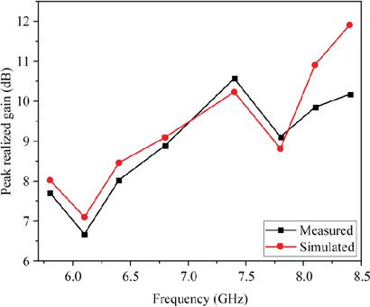
Figure 12 Comparison of simulated and measured gains of the proposed SSPP antenna.
Table 2 compares the performance of the SSPP antenna designed in this paper with other SSPP antennas listed in [17, 19, 20, 21, 22]. It can be seen that while ensuring a wide scanning angle of 71∘, the proposed design has a smaller electrical size of only , and its bandwidth is limited to 2.6 GHz, achieving the goal of balancing scanning rate and miniaturization, with better performance.
Table 2 Performance comparison between SSPP antennas
| Ref. | Bandwidth (GHz) | Scanning Range | Max Gain (dBi) | Antenna Size |
| 17 | 3 (6–9) | 55∘ | 11 | () |
| 19 | 16 (8–24) | 12.5 | () | |
| 20 | 2 (5–7) | 81∘ | 19.4 | () |
| 21 | 4.5 (2.87.3) | 10.23 | () | |
| 22 | 5 (7–12) | 10.3 | () | |
| This Work | 2.6 (5.88.4) | 10.17 | () |
4 CONCLUSION
In this paper, a wide angle and high scanning rate leaky-wave antenna based on SSPP structure is designed, fabricated and tested. The side of the proposed structure adopts a uniform metal strip structure, and a periodic radiation patch is loaded above it to couple the electromagnetic energy from the SSPP structure and radiate it into free space. The periodic metal ripple modulation is introduced on the other side, and the overall asymmetric structure is used to improve the scanning angle range, suppress the side lobe and improve the scanning rate.
ACKNOWLEDGMENT
The authors wish to acknowledge the support of Open Project of Millimeter Wave Key Laboratory (K202431).
REFERENCES
[1] M. Francesco and A. Alu, “Leaky-wave theory, techniques, and applications: From microwaves to visible frequencies,” Proceedings of the IEEE, vol. 103, no. 5, pp. 793–821, 2015.
[2] Q. L. Zhou, B. W. Zhang, N. W. Liu, and G. Fu, “A high-gain low-sidelobe dual-polarized broadband array antenna,” Applied Computational Electromagnetics Society (ACES) Journal, vol. 39, no. 01, pp. 24–30, Jan. 2024.
[3] W. Menzel and A. Moebius, “Antenna concepts for millimeter-wave automotive radar sensors,” Proceedings of the IEEE, vol. 100, no. 7, pp. 2372–2379, July 2012.
[4] H. O. Hanoosh, M. K. A. Rahim, N. A. Murad, and Y. M. Hussein, “A 33 antenna beamforming network based on waveguide Nolen matrix for Ka-bands,” IEEE Access, vol. 12, pp. 151893–151906, 2024.
[5] L. Cui, W. Wu, and D. G. Fang, “Printed frequency beam-scanning antenna with flat gain and low sidelobe levels,” IEEE Antennas Wireless Propag. Lett., vol. 12, pp. 292–295, 2013.
[6] Y. M. Hussein, M. K. A. Rahim, N. A. Murad, and H. O. Hanoosh, “Low loss wideband 44 Butler matrix networks based on substrate integrated waveguide for 5G applications,” IEEE Access, vol. 12, pp. 7896–7910, 2024.
[7] G. Lovat, P. Burghignoli, and D. R. Jackson, “Fundamental properties and optimization of broadside radiation from uniform leaky-wave antennas,” IEEE Trans. Antennas Propag., vol. 54, no. 5, pp. 1442–1452, May 2006.
[8] H. Yi, S. W. Qu, and X. Bai, “Antenna array excited by spoof planar plasmonic waveguide,” IEEE Antennas Wireless Propag. Lett., vol. 13, pp. 1227–1230, 2014.
[9] M. H. Rahmani and D. Deslandes, “Backward to forward scanning periodic leaky-wave antenna with wide scanning range,” IEEE Trans. Antennas Propag., vol. 65, no. 7, pp. 3326–3335, July 2017.
[10] K. Rudramuni, K. Kandasamy, A. Kandwal, and X.-L. Tang, “Goubau-line leaky-wave antenna for wide-angle beam scanning from backfire to endfire,” IEEE Antennas Wireless Propag. Lett., vol. 17, no. 8, pp. 1571–1574, Aug. 2018.
[11] Z. Fu, T. Zhang, T. Wu, Y. Lan, W. Huang, and L. He, “Wide-angle frequency scanning leaky-wave antenna loaded CSRR patch based on SSPP transmission line,” International Journal of Antennas and Propagation, vol. 21, no. 83, pp. 1–11, Apr. 2019.
[12] J. Liu, D. R. Jackson, and Y. Long, “Substrate Integrated Waveguide (SIW) leaky-wave antenna with transverse slots,” IEEE Trans. Antennas Propag., vol. 60, no. 1, pp. 20–29, Jan. 2012.
[13] D. K. Karmokar, S. L. Chen, D. Thalakotuna, P.-Y. Qin, T. S. Bird, and Y. J. Guo, “Continuous backward-to-forward scanning 1-D slot-array leaky-wave antenna with improved gain,” IEEE Antennas Wireless Propag. Lett., vol. 19, no. 1, pp. 89–93, Jan. 2020.
[14] X. P. Shen and T. J. Cui, “Conformal surface plasmons propagating on ultrathin and flexible films,” Proceedings of the National Academy of Sciences, vol. 110, no. 1, pp. 40–45, 2013.
[15] L. Li, P. Chen, P. Zhu, and K. Yang, “A compact rejection filter based on spoof surface plasmon polaritons and folded split-ring resonators with controllable rejection bandwidth,” Applied Computational Electromagnetics Society (ACES) Journal, vol. 34, no. 9, pp. 1405–1410, Sep. 2019.
[16] Y. Song and A. Zhang, “Balanced filtering power divider based on odd-mode hybrid microstrip and slotline spoof surface plasmon polaritons,” Applied Computational Electromagnetics Society (ACES) Journal, vol. 38, no. 07, pp. 532–538, July 2023.
[17] J. Y. Yin, J. Ren, and Q. Zhang, “Frequency-controlled broad-angle beam scanning of patch array fed by spoof surface plasmon polaritons,” IEEE Trans. Antennas Propag., vol. 64, no. 12, pp. 5181–5189, Dec. 2016.
[18] D. F. Guan, P. You, Q. Zhang, Z.-H. Lu, S.-W. Yong, and K. Xiao, “A wide-angle and circularly polarized beam-scanning antenna based on microstrip spoof surface plasmon polariton transmission line,” IEEE Antennas Wireless Propag. Lett., vol. 16, pp. 2538–2541, 2017.
[19] L. L. Liu, J. Wang, X. Yin, and Z. N. Chen, “Wide-angle beam scanning leaky-wave antenna using spoof surface plasmon polaritons structure,” Electronics, vol. 7, no. 12, p. 348, 2018.
[20] D. Wei, J. Li, J. Yang, Y. Qi, and G. Yang, “Wide-scanning-angle leaky-wave array antenna based on microstrip SSPPs-TL,” IEEE Antennas Wireless Propag. Lett., vol. 17, no. 8, pp. 1566–1570, Aug. 2018.
[21] H. R. Zhu, B. Wu, and Q. S. Cheng, “Dual-frequency-scanning broadband antenna based on Z-shape spoof surface plasmon polaritons,” Applied Physics Express, vol. 12, no. 8, p. 084001, 2019.
[22] J. Y. Yin, X. Y. Cao, and J. Y. Deng, “Continuously beam-scanning leaky-wave antenna based on impedance-matched spoof surface plasmon polaritons,” IEEE Antennas Wireless Propag. Lett., vol. 22, no. 9, pp. 2080–2084, Sep. 2023.
BIOGRAPHIES

Xiaoyan Zhang received the B.S. degree in applied physics and M.S. degree in physical electronics from Yunnan University, Kunming, China, in 2001 and 2004, respectively, and the Ph.D. degree in Electromagnetic Field and Microwave Technology from Institute of Electronics, Chinese Academy of Sciences, in 2007. Her research interests include electromagnetic computation, antenna design and wireless power transmission structure design.

Siyuan Yu was born in 1999 in Ningbo, Zhejiang Province, China. He obtained a bachelor ’s degree in engineering from Wuxi Taihu University, Jiangsu, China, and is now studying in the School of Information Engineering, East China Jiaotong University. His main research direction is antenna design.

Aiyun Zhan was born in Nantong, Jiangsu, China, in 1973. She received the B.S. degree from Southwest Jiaotong University in 1997, and M.S. degree from East China Jiaotong University in 2008. She is currently working at the School of Information Engineering, East China Jiaotong University. Her research interests focus on channel coding and optical communication.

Yan Mei obtained the bachelor’s degree in communication engineering from the School of Information and Communication, National Defense University of the People’s Liberation Army of China, in 2002, and the master’s degree in computer science and technology from East China Jiaotong University in 2009. Her research interests include wireless communication and deep learning.
ACES JOURNAL, Vol. 41, No. 5, 449–456
DOI: 10.13052/2026.ACES.J.410507
© 2026 River Publishers