Discussion of the Transmission Efficiency of Quasi-optical Reflector Antenna Across Various Levels of Feeder Performance
Haoran Zhang and Ming Jin
College of Information Science and Technology
Beijing University of Chemical Technology, 100191 Beijing, China
2023210600@mail.buct.edu.cn, jinming@mail.buct.edu.cn
Submitted On: November 6, 2024; Accepted On: January 24, 2025
ABSTRACT
For microwave radiometer calibration, higher main beam efficiency reduces interference from environmental brightness temperature (BT). A key challenge for high-frequency microwave sounders is achieving high main beam efficiency with limited mirror size. Although efficiency has improved to around 95-98%, there is still room for improvement. This study investigates the main beam efficiency of ground-based radiometer antenna systems, considering feeders with different radiating qualities and mirror conditions. A quasi-ellipsoidal mirror with feeders operating at multiple discrete frequencies is designed to optimize the optical path for microwave calibration. The key focus is transmission efficiency, which affects BT leakage. Numerical results for various feeders are compared - straight wall corrugated horns with 98.2% Gaussian content, dual-mode horns with 98.5%, curved wall corrugated horns with 99.8%, and ideal Gaussian beams - highlighting achievable transmission levels in different polarizations with different feeders. Design curves for the high main beam efficiency quasi-optical reflector antenna system are provided. Such information is beneficial and of direct referencing value for practical radiometer reflector antenna designs.
Index Terms: Brightness temperature leakage, microwave radiometer calibration, quasi-optical reflector antenna.
I. INTRODUCTION
The microwave radiometer payload performs an important part in remote sensing techniques for monitoring the earth environment from surface to atmosphere [1, 2]. As the radiometer payloads passively detect weak and non-coherent thermal radiation from the earth environment, its antenna needs high gain, low side-lobe characteristics [3]. Thus, reflector antennas are often used in microwave radiometer systems.
The quasi-optical (QO) reflector antenna [4, 5] is a kind of compact reflector antenna which is suitable for applications of microwave sounders. It is based on optical system design ideas, where electromagnetic waves propagate in the form of a Gaussian beam in free space, and the width and curvature of the Gaussian beam can be controlled by the mirror, lens and other devices. A well-designed QO reflector antenna leads to less leakage, which is significant in radiometer applications.
Specifically in the calibration process, which is vital for radiometer quantitative observation, the leakage from the reflector antennas is an important factor, which should be suppressed as much as possible [6–11]. As can be found in the reported microwave radiometer payloads [6, 7, 9, 11], achieved main beam efficiency is at a level of 0.950.98. Comparatively, the emissivity level of a modern calibration target is 0.9990.9999, which is another source of leakage disturbing calibration accuracy [12–14]. It can be concluded, leakage from the reflector antenna is a significant factor contributing to calibration error, as it leads to the notable intrusion of background brightness temperature (BT) which is generally hard to control or accurately model.
To minimize the leakage caused by reflectors, main beam efficiency needs to be further improved. However, there are no design guidelines specifically for achieving high main beam efficiency in QO reflector antennas. During designing a low-leakage QO antenna for a ground-based radiometer calibration test system with accuracy demands, the authors developed a set of prototypes with various levels of feeder performance, which leads to a comprehensive database for the quantitative conclusion for low-leakage design. In this work, the authors will demonstrate the quantitative analysis with further considerations of factors such as reflector size and polarization, forming a direct reference for designers of radiometer reflector antennas.
II. FORMULA DEFINITION
In this work, the authors utilized the factor of Gaussian content, which is the similarity level between horn antenna fields and the pure Gaussian fields of fundamental mode [15, 16], to govern the performance of the feeder. To further improve calibration accuracy, it is significant that the QO reflector antenna [17] can be with a main beam efficiency notably higher than the current level of 0.950.98. High main beam efficiency is linked to the Gaussian content of the feeder horn, which is a qualitative acknowledgement. However, it is of practical referencing value if the quantitative reference can be given, including both the factors of feeder Gaussian content and reflector size.
In this section, the authors will give specific definitions of Gaussian content and main beam efficiency in this analysis.
A. Gaussian content
Gaussian fundamental mode scalar field distribution can be expressed as:
| (1) |
is the transverse position vector diameter perpendicular to the propagation direction, , , z is the propagation distance along the propagation direction (z-axis). z is 0 at the waist of the Gaussian beam (radius of the waist ):
| (2) | ||||
| (3) | ||||
| (4) |
For the main polarization field of the horn antenna, which is based on CST, the Gaussian content can be obtained at the radiation interface:
| (5) |
Figure 1 (a) shows the field (dB) in CST and Fig. 1 (b) shows the field (linear) in our field analyses.
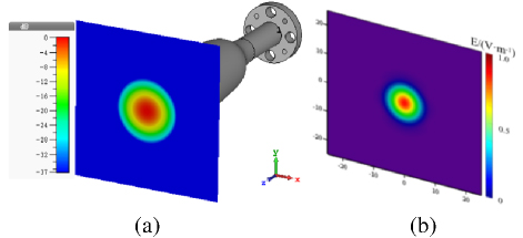
Figure 1: Main polarization field of the horn antenna.
B. Main beam efficiency and leakage
If a sufficiently large cross-section A is taken near the front of the feed opening, the edge field is attenuated significantly. The field distribution on the interface is E, H, and the incident power is obtained by integrating the surface flux of the Poynting vector:
| (6) |
After passing behind the mirror far enough (across the observation area), take a cross-section A equal to the size of the reflector, define the exit field distribution of the cross-section as E, H, and obtain the exit power by integrating the surface flux of the Poynting vector:
| (7) |
Main beam efficiency (power transfer efficiency) is defined as:
| (8) |
Power transmission leakage is defined as:
| (9) |
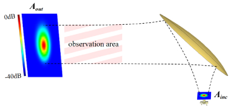
Figure 2: Main beam efficiency analysis scenario.
III. RESULTS AND COMPARISONS
In this part, the authors introduce the different kinds of feed horns used in QO antenna, and main beam efficiency is compared in different conditions.
The horn antennas here include the common horns which are often used in radiometer antenna system, such as the curved wall corrugated horn, the linear wall corrugated horn and the dual-mode horn [18, 19]. The far-field and near-field information of the reflector antenna are given, which can visually show the leakage of the reflector. Simulation value of main beam efficiency is discussed with different frequencies, polarization, kinds of feed horns and size of reflectors, which is significant to the design of radiometer reflector antenna system.
A. Horn antennas
This part introduces the structure and performance of feed horns which are often used in radiometers with three frequencies of 54, 89 and 118 GHz. The types of the feeders are the curved wall corrugated horns, linear profile corrugated horns and dual-mode conical horns (dual-mode horn is only designed in 89 and 118 GHz). Taking the design of 89 GHz frequency as an example, the typical structure of the feeds is shown in Fig. 3.
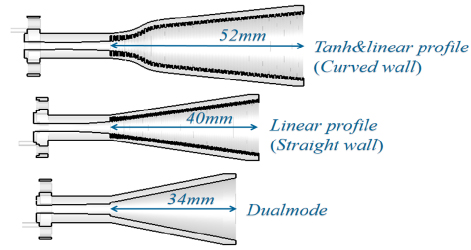
Figure 3: 89 GHz feed horns.
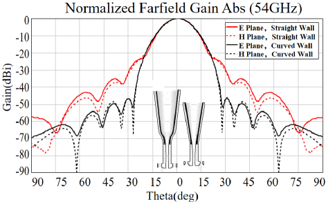
Figure 4: 54 GHz far-field pattern. Red lines mark the angular coverage of the QO reflector with cross-section radius L0.1 m, and the distance Zc from the feed Gaussian waist position to the center of the reflector is 0.155 m.
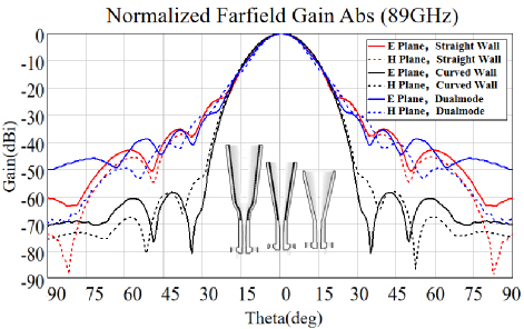
Figure 5: 89 GHz far-field pattern.
The far-field pattern of the feed horn of each frequency is shown in Figs. 4–6. These feed horns can get a pretty good performance in far-field pattern that the side-lobe level is below -35 dB. It is worth noting that that far-field pattern of the curved wall corrugated horn rapidly rolls down with , which is important for a high-performance radiometer reflector antenna.
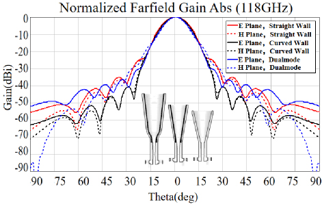
Figure 6: 118 GHz far-field pattern.
As shown in Table 1, the Gaussian parameters of all feed horns at the three frequencies are summarized. The curved wall corrugated horn has the highest Gaussian content level of more than 99.5%, the straight wall corrugated horn and the dual-mode horn have a Gaussian content around 98.5%.
Table 1: Gaussian parameters of the feed horn
| Feed Horn | / | Gaussian Content |
| Tanh&linear profile corrugated horn (54 GHz) | 1.430.02 | 99.85% |
| Linear profile corrugated horn (54 GHz) | 1.430.02 | 98.35% |
| Tanh&linear profile corrugated horn (89 GHz) | 1.430.02 | 99.8% |
| Linear profile corrugated horn (89 GHz) | 1.430.02 | 98.2% |
| Dual-mode horn (89 GHz) | 1.430.02 | 98.8% |
| Tanh&linear profile corrugated horn (118 GHz) | 1.640.02 | 99.7% |
| Linear profile corrugated horn (118 GHz) | 1.640.02 | 98.2% |
| Dual-mode horn (118 GHz) | 1.640.02 | 98.5% |
B. Reflectors of different sizes
Information on the sufficient size of reflector for achieving a specific main beam efficiency is generally interesting for radiometer antenna designers. To conclude that information, the reflector instance is set to be with different truncated sizes for expanding the data range. Specifically, as shown in Fig. 7, L refers to the cross-section size of reflector and (z) refers to the ideal Gaussian beam waist radius when the beam propagates to the center of the mirror, so that the relative size of the reflectors can be understood as L/(z). Our analysis of main beam efficiency includes five sizes of reflectors, which can help examine the relationship between main beam efficiency and the relative size of reflectors.
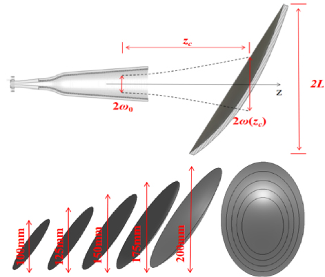
Figure 7: Relationship between (z) and L.
C. Comparison of reflected fields in far-field and near-field
In this section, the authors showcase the reflected fields of 89 GHz, to help understand the phenomenon of reflector leakage. To the author’s knowledge, the most important reason for reflector leakage is insufficient size of reflector for covering the diffusing fields from the small-aperture feeder. Meanwhile from the view of feeders, the ability to suppress wasted radiation in far off-axes angles is important for achieving high main beam efficiency. In the analysis, there are three different feeders - straight wall corrugated horn, dual-mode horn and curved wall corrugated horn - which have different levels of Gaussian content related to far off-axes side-lobe performance. Considering a relatively small reflector size (L0.1 m), one can easily see the power leakage in the 3D far-field pattern in Fig. 8, referenced with a pure Gaussian beam illumination. The Gaussian beam and curved wall corrugated horn cause less power leakage, while the straight wall corrugated horn can cause obvious power leakage.
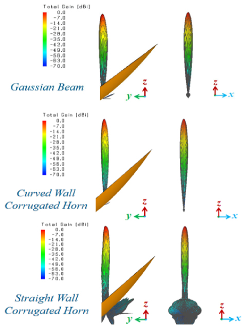
Figure 8: 89 GHz normalized far-field pattern (from 0 to -70 dB [20]).
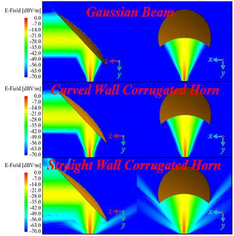
Figure 9: 89 GHz near-field plane (from 0 to -70 dB [20]).
Figure 9 shows how power transmission leakage occurs at 89 GHz. Specifically, the reason is the relative size between the beam width and the reflector. With the increase of Gaussian content level, leakage obviously decreases, which shows the significance of Gaussian content level of feed horns in radiometer reflector antennas. The normalized reflected electric fields of 89 GHz are shown in Fig. 10. We can see that the reflected fields of Gaussian beam have the characteristics of power focusing and edge attenuation. The reflected fields of the curved wall corrugated horn are similar to the reflected fields of the Gaussian beam, while the reflected fields of the straight wall corrugated horn have poor beam quality, which means the straight wall corrugated horn (with a Gaussian content about 98.2%) will have a relatively bad performance in radiometer reflector antenna applications.
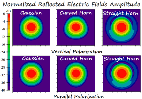
Figure 10: 89 GHz normalized reflected electric fields amplitude (dB), considering the reflector with a cross-section radius L100 mm, which leads to notably higher than 0.99.
When further calculating main beam efficiency using equations (7) and (8), the direct integrated physical optics (PO) algorithm is used, as it will not introduce numerical influences caused by the iterative solving process of the full-wave MLFMA (multi-layer fast multi-pole algorithm) of FEKO. However, as the diffraction algorithm is not included, the PO calculated fields do not contain the edge diffraction effects. Therefore, a method investigation has to be made on whether the edge diffraction effect is notable in the main area of considered parameter region.
Specifically, the authors compared the reflected fields by their PO and FEKO solvers (Fig. 11), in the case of the 89 GHz straight wall corrugated horn, and L/w(z)2.167 (L0.075 m). In this case, is around 99%, which is the main parameter region where investigations are focused.
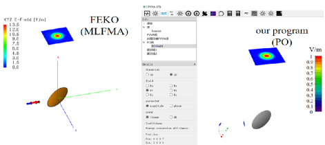
Figure 11: Configuration of reflected fields calculation by FEKO (full wave MLFMA) left, and by our program based on physical optics (PO) right.
For the first comparison, the authors took a cross-section aperture of 0.2 m. The reflected fields are shown in the 40 dB dynamic range (Fig. 12), and the correlation between FEKO results and results from our program is above 0.999, as shown in Fig. 12. Thus, the PO calculation gives accurate results in the main-beam area. Further, in order to find field leakage caused by edge diffraction off the main-beam path, the authors took a larger cross-section area of 0.6 m. The reflected fields are shown in the 40 dB dynamic range and 60 dB dynamic range in Fig. 13. It can be observed that, for the weak diffracted pattern away from the main-beam path, there are indeed differences in the two sets of results. However, the fields in the pattern-differed area are very weak compared to those in the main-beam area. Therefore, PO calculation is sufficient for field and further main beam efficiency analysis for cases of 99%, without considering edge diffraction. However, it should be noted that, when reflected fields investigation is performed when is notably lower, (0.950.98), edge diffraction should be included in the analysis.
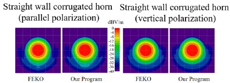
Figure 12: Comparison between reflected field results of straight wall corrugated horn at 89 GHz in cases of parallel-pol and vertical-pol reflection (correlation efficiency between results by the two methods achieves a level of 0.999).
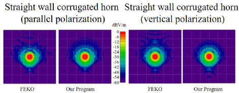
Figure 13: Comparison of reflected field results by FEKO and PO: 89 GHz reflected fields of straight wall corrugated horn, parallel-pol and vertical-pol reflection (40 dB dynamic range, upper row, and 60 dB dynamic range, lower row).
D. Main beam efficiency
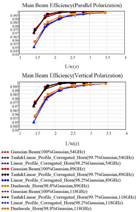
Figure 14: Counted main beam efficiency (parallel-pol and vertical-pol).
Next, the achieved main beam efficiency is calculated and analyzed in considered feeders at different frequencies of different beam waist radius and reflectors of different sizes. Figure 14 quantitatively shows the feeders with Gaussian content of about 98.5% and 99.5%, whose main beam efficiency changes with the relative size of the reflector. The vertical ordinates of Fig. 14 are main beam efficiency, and the horizontal ordinates are relative size of reflector (normalized by the equivalent beam waist radius of the propagated fields at the reflector). Main beam efficiency rises with Gaussian content. For example, Gaussian content of the pure Gaussian beam and curved corrugated horn are similar, and their main beam efficiency curves are similar too. Equally, the dual-mode horn antenna and linear profile corrugated horn show the same regularity.
A common horn antenna with 98.5% Gaussian content needs L3(z) to attain a high main beam efficiency of 99.5%. This is important in the design of radiometer reflectors.
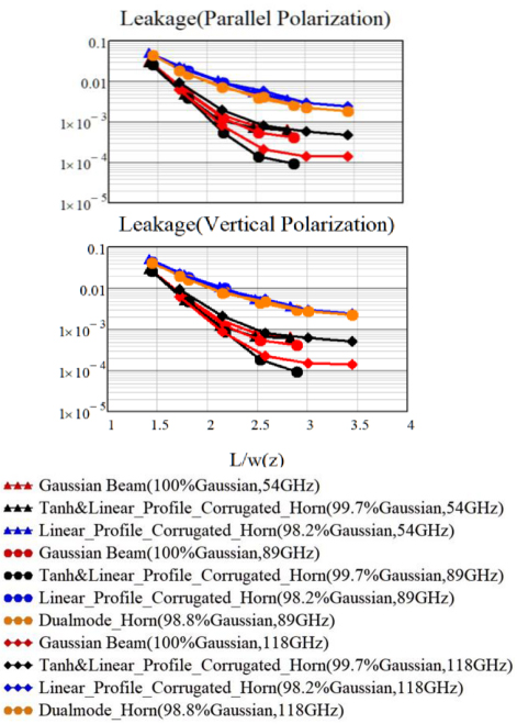
Figure 15: Counted main beam efficiency (parallel-pol and vertical-pol).
E. Leakage
Power transmission leakage can be obtained by main beam efficiency from Fig. 14. Figure 15 shows the leakage when different horns irradiate different sizes of reflector antenna systems. In order to facilitate observation and analysis, a logarithmic scale is used in Fig. 15. After averaging the leakage of Gaussian beam and curved wall corrugated horns, we have a clearer insight on the leakage information shown in Fig. 16.
Regarding practical applications in radiometer systems, leakage of the QO reflector antenna is becoming notable for achieving a high-accuracy BT transfer, as progress in other factors have been made in recent years [6, 7, 9, 11]. For example, leakage from the calibration target can be reduced to a level of 0.0001 (emissivity40 dB), while leakage from the reflector can be at a level over 0.01 (0.99, from the reported radiometer payloads design). The results of this work clearly indicate that achieving Gaussian content in the feeder (or QO feeder network) fields to the state-of-the-art level is of practical significance. This is particularly important for enhancing main beam efficiency when reflector sizes are limited.
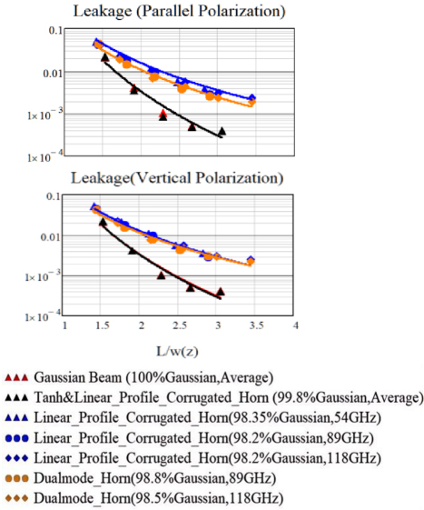
Figure 16: Leakage of the reflector antenna (curve fitting, parallel-pol and vertical-pol).
F. Additional fabricated Ka-band instance
It is interesting and important that the curves in sections III D and E are of reference value to general QO designs. Therefore, in this section, a fabricated Ka-band feeder and its paired QO reflector are considered as in Fig. 17 (a). The feeder is a typical straight wall corrugated horn antenna, and it shall be noted that the Ka-band is out of the range of data instances in section III. The aperture fields of the Ka-band feeder are tested in Figs. 17 (b) and 18 (a). The reflected fields (parameters listed in Table 2) are calculated to show the achieved main beam efficiency, for comparison with concluded curves in section III.
| Parameter | Length/m |
| cross-section of reflector (L) | 0.1 |
| radius of curvature 1 (R) | 0.137 |
| radius of curvature 2 (R) | 0.512 |
| incident distance (d) | 0.13 |
| exit distance (d) | 0.287 |
In the specific calculation of main beam efficiency, the equivalent waist radius of the tested field was determined to be 1.08. From this, the beam waist radius at the reflector was calculated to be 4.25. Subsequently, the reflected fields were computed (see Figs. 18 (b) and 19) to evaluate the main beam efficiency. The results are presented in Fig. 20, where a comparison with the curves derived in section III is made. As shown in Fig. 20, the results exhibit good agreement with the previously concluded curves. This example demonstrates that the curves presented in section III have practical reference value for typical QO designs.
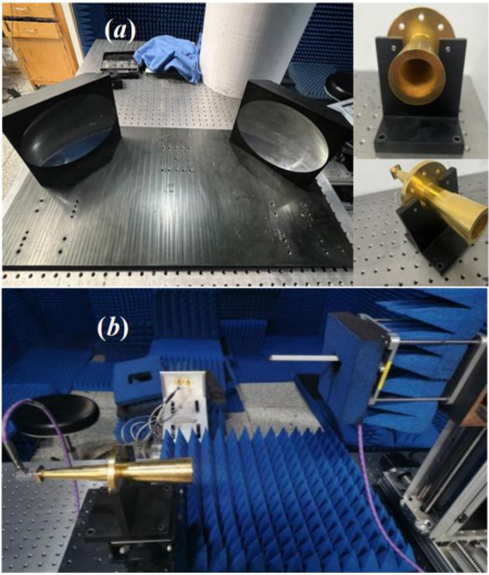
Figure 17: The considered fabricated Ka-band straight wall feeder antenna and its aperture field testing configuration. (a) Feeder antenna and its paired QO reflector and (b) aperture field testing configuration (planar field scanning). (Feeder antenna and testing facility provided by the microwave engineering laboratory in Beihang University.)
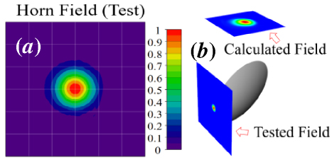
Figure 18: (a) Tested fields of the Ka-band feeder and (b) computation configuration for the reflector reflected fields.
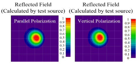
Figure 19: Reflected fields in two polarization cases.
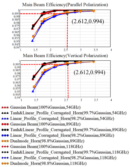
Figure 20: Counted main beam efficiency results based on the tested Ka-band feeder aperture fields, and comparison with concluded curves based on 54 GHz/89 GHz/118 GHz feeders.
IV. DISCUSSION
This study is driven by the need to improve QO reflector main beam efficiency, which is becoming a notable obstructive factor in improving radiometer calibration accuracy. Compared with reported main beam efficiency level at 9598% in applied radiometer payloads, this study investigates the strategy to achieve main beam efficiency higher than 99%, and that (99%) may be still not be enough for future requests from radiometer designers.
This study explores the relationship between power transmission leakage and reflector antenna design, considering different frequencies, Gaussian content of feeds and reflector sizes. Notably, the power transmission leakage for various frequencies follows a similar trend. It is clear that, besides the reflector size, the Gaussian content achieved by the feeder is alsosignificant.
It is worth emphasizing that the rapid roll-off of the far-field pattern (feeder) is crucial for pursuing high efficiency at the cutting edge, which is shown for the curved-wall corrugated horn in Figs. 4–6. As can be found in Fig. 16, a very large reflector can be used with a 98.5% Gaussian content feed (straight wall horn or dual-mode horn), for pursing a 99.9% level of main beam efficiency. Further, it should also be noted, in the QO systems, beam propagation from the feeder to the reflector should not be directly considered as far-field but is a near-field process. Reflector leakage is found to be larger than it seems in the far-field pattern. For example, as shown in Fig. 4, angular coverage of the reflector with a L0.1 m can be for the 54 GHz feeder (distance Z between the feeder Gaussian waist to the center of reflector is 0.155 m). Out of that angular region, the side-lobes are smaller than -30 dB for the straight wall corrugated feed (shown in Fig. 4), but the counted main beam efficiency is 0.996, which means a leakage notably larger than -30 dB happens.
The authors present these results to provide a universal reference for the design of QO reflector antennas aimed at achieving extremely high efficiency. Figure 14 shows the main beam efficiency values that a common radiometer reflector antenna can achieve according to different reflector sizes with different types of feeder antennas. The instance of Ka-band straight wall corrugated horn conforms the validity of the concluded curves as a common reference. It is clear that, for achieving an extremely high main beam efficiency, such as 0.999, the Gaussian quality of the QO feeder is significant. For example, if an extremely high performance QO reflector antenna is required with leakage less than 0.001, a reflector with L2.5(z) and a well-designed horn with 99.5% (Gaussian content) isnecessary.
Although the calculated result of the main beam efficiency in Ka-band is in agreement with the analysis results of straight wall corrugated feeders, it is regrettable that is not a measured value. When 0.99, measuring the main beam efficiency becomes a technical challenge and requires further methodology development. The authors plan to further investigate the high efficiency QO reflector system (or the QO feed network), as it becomes significant for improving radiometer calibration accuracy. However, the investigations should focus on both the design implementation and the measurement validation.
V. CONCLUSION
In this paper, the authors analyzed the power transmission leakage of a reflector antenna under different feed types. The high Gaussian feed horn, characterized by its rapid roll-off in the far-field pattern, demonstrated superior performance in this study. Additionally, the power transmission leakage of the reflector antenna was quantitatively analyzed across various levels of feeder performance. These findings are universally applicable and hold practical significance for the design of high-performance reflector antennas used in radiometers.
ACKNOWLEDGMENT
The authors appreciate the help from Professor Ming Bai and Dr. Ning Leng at the Microwave Engineering Laboratory, Beihang University, for providing the measurement facility & equipment and technique support.
REFERENCES
[1] D. Draper, Q. Remund, D. Newell, and S. Krimchansky, “A comparison of GPM Microwave Imager (GMI) high frequency channel brightness temperatures to the Advanced Technology Microwave Sounder (ATMS),” in IEEE International Geoscience and Remote Sensing Symposium (IGARSS), Milan, Italy, pp. 5146-5149, 2015.
[2] N. Sun and F. Weng, “Evaluation of Special Sensor Microwave Imager/Sounder (SSMIS) environ-mental data records,” IEEE Transactions on Geoscience and Remote Sensing, vol. 46, no. 4, pp. 1006-1016, Apr. 2008.
[3] M. Jin, R. Yuan, X. Li, Y. Tao, Q. Gao, and M. Bai, ”Wideband microwave calibration target design for improved directional brightness temperature radiation,” IEEE Geoscience and Remote Sensing Letters, vol. 19, pp. 1-5, 2022.
[4] Z. Li, Y. Zhang, K. Liu, D. Liu, and J. Miao, “A millimeter and sub-millimeter wave multi-channel quasi-optical system for microwave radio-meter,” in IEEE Geoscience and Remote Sensing Symposium, Quebec City, QC, Canada, pp. 3033-3036, 2014.
[5] A. L. Woodcraft, S. T. Froud, R. J. Wylde, P. A. R. Ade, R. V. Sudiwala, C. E. Tucker, S. M. Tun, M. Bray, P. Campbell, G. Maxwell-Cox, and V. Kangas, “Design and testing of the quasi-optical network for the MetOp-SG microwave sounder,” in 17th European Conference on Antennas and Propagation (Eu-CAP), Florence, Italy, pp. 1-5, 2023.
[6] W. Hongjian, “Design and analysis of FengYun3 Microwave Humidity Sounder (FY3MHS) Antenna,” in IEEE International Symposium on Antennas and Propagation and USNC-URSI Radio Science Meeting, Atlanta, GA, USA, pp. 471-472, 2019.
[7] I. A. Osaretin, M. W. Shields, J. A. M. Lorenzo, and W. J. Blackwell, “A compact 118-GHz radiometer antenna for the micro-sized microwave atmospheric satellite,” IEEE Antennas and Wireless Propagation Letters, vol. 13, pp. 1533-1536, 2014.
[8] V. Kangas, S. D’Addio, G. Mason, M. Buckley, G. Tennant, and P. Campbell, “Microwave sounder instrument for MetOp second generation,” in 13th Specialist Meeting on Microwave Radiometry and Remote Sensing of the Environment (MicroRad), Pasadena, CA, USA, pp. 232-235, 2014.
[9] R. Dey, R. Ram, S. Kulshrestha, V. K. Singh, and M. B. Mahajan, “Design and development of antenna system for millimeter-wave humidity sounder payload,” in IEEE Microwaves, Antennas, and Propagation Conference (MAP-CON), Ahmedabad, India, pp. 1-4, 2023.
[10] W. J. Blackwell, “Antenna development for microwave sounding CubeSats,” in IEEE Inter-national Symposium on Antennas and Propagation (APSURSI), Fajardo, PR, USA, pp. 1537-1538, 2016.
[11] R. Albers, A. Emrich, and A. Murk, “Antenna design for the arctic weather satellite micro-wave sounder,” IEEE Open Journal of Antennas and Propagation, vol. 4, pp. 686-694, 2023.
[12] E. Kim, V. Leslie, J. Lyu, C. Smith, I. Osaretin, S. Abraham, M. Sammons, K. Anderson, J. Amato, J. Fuentes, M. Hernquist, M. Landrum, F. Rodriguez-Gutierrez, J. Kam, P. Cho, H. Yang, Q. Liu, and N. Sun, “Pre-launch performance of the Advanced Technology Microwave Sounder (ATMS) on the Joint Polar Satellite System-2 Satellite (JPSS-2),” in IEEE International Geoscience and Remote Sensing Symposium, Waikoloa, HI, USA, pp. 6353-6356, 2020.
[13] D. A. Houtz, W. Emery, D. Gu, K. Jacob, A. Murk, D. K. Walker, and R. J. Wylde, “Electromagnetic design and performance of a conical microwave blackbody target for radiometer calibration,” IEEE Transactions on Geoscience and Remote Sensing, vol. 55, no. 8, pp. 4586-4596, Aug. 2017.
[14] K. Jacob, A. Schröder, L. von Werra, F. Reinhard, P. Raisin, and A. Murk, “Radiometric characterization of a water-based conical blackbody calibration target for millimeter-wave remote sensing,” IEEE Journal of Selected Topics in Applied Earth Observations and Remote Sensing, vol. 12, no. 6, pp. 1688-1696, June 2019.
[15] L. Cheng, Y. Li, X. Zhang, L. Xia, Y. Yang, and P. Li, “A fast and accurate design method for the smooth-walled horn antenna with a high Gaussian coupling efficiency,” in 16th UK-Europe-China Workshop on Millimetre Waves and Terahertz Technologies (UCMMT), Guang-zhou, China, pp. 1-3, 2023.
[16] L. Cheng, F. Wu, Y. Zhou, D. Li, Y. Yang, and L. Jin, “Study on horn antenna with a high Gaussian coupling efficiency,” in CIE International Conference on Radar (Radar), Haikou, Hainan, China, pp. 1976-1979, 2021.
[17] B. Li, M. Jin, M. Bai, and Z. Li, “Quasi-optical antennas design in the standard measurement facility on the emissivity from microwave calibration targets,” Journal of Astronautic Metrology and Measurement, vol. 38, no. 6, pp. 9-15, 2018.
[18] J. E. McKay, D. A. Robertson, P. J. Speirs, R. I. Hunter, R. J. Wylde, and G. M. Smith, “Compact corrugated feedhorns with high Gaussian coupling efficiency and -60 dB sidelobes,” IEEE Transactions on Antennas and Propagation, vol. 64, no. 6, pp. 2518-2522, June 2016.
[19] F. Teng, J. Wan, and J. Liu, “Design of a 118 GHz corrugated horn based on the modal analysis,” in IEEE International Workshop on Electromagnetics: Applications and Student Innovation Competition (iWEM), Guangzhou, China, pp. 1-3, 2021.
[20] FEKO. Altair Engineering, Inc., Troy, MI, 2020.
BIOGRAPHIES

Haoran Zhang received the B.Sc. degree from Beijing University of Chemical Technology (BUCT) in 2023, where he is now pursuing his master’s degree. His research interest is the design of quasi-optical antennas.

Ming Jin received the B.Sc. and Ph.D. degrees from Beihang University (BUAA), Beijing, China, in 2007 and 2013, respectively. From 2007 to 2012, he was a research assistant in the Microwave Engineering Laboratory, Beihang University. From December 2010 to March 2011, he was a Visiting Scholar at Arizona State University. In 2019, he joined the College of Information Science and Technology, Beijing University of Chemical Technology (BUCT) as an associate professor. His research interests include microwave radiometer calibration techniques, quasi-optical beam propagation and computational electromagnetics.
ACES JOURNAL, Vol. 40, No. 2, 138–147
doi: 10.13052/2025.ACES.J.400207
© 2025 River Publishers