Electromagnetic Characteristics Comparative Investigation of Five-phase Wide-and-Narrow Stator Poles Axial Flux Switched Reluctance Motors with Different Rotor Poles Number
Fengyuan Yu, Xing Wang, Hao Chen, Wenju Yan, Hongwei Yang,Popov Stanislav Olegovich, Bodrenkov Evgenii Alexandrovich,Nurkhat Zhakiyev, and Yassen Gorbounov
1School of Electrical Engineering
China University of Mining and Technology, Xuzhou 221116, China
fyyu@cumt.edu.cn, hchen@cumt.edu.cn, yanwenju09@126.com, ts22230175p31@cumt.edu.cn
2International Joint Research Center of Central and Eastern European Countries on
New Energy Electric Vehicle Technology and Equipment
Xuzhou 221008, China
3512@cumt.edu.cn
3Shenzhen Research Institute
China University of Mining and Technology
Shenzhen 518057, China
4Institute of Energy
Peter the Great Saint-Petersburg Polytechnic University
195251 Saint Petersburg, Russia
popovso@spbstu.ru, bodrenkovea@spbstu.ru
5Department of Science and Innovation
Astana IT University, Astana, Kazakhstan
nurkhat.zhakiyev@astanait.edu.kz
6Department of Informatics
New Bulgarian University, Sofia 1618, Bulgaria
y.gorbounov@mgu.bg
Submitted On: December 25, 2024; Accepted On: September 8, 2025
ABSTRACT
Axial flux switched reluctance motors (AFSRMs) offer advantages such as a large air-gap surface area, compact structure, and high torque density. This paper proposes a novel five-phase AFSRM structure featuring wide-and-narrow stator poles (NWS-AFSRM) and presents a comparative study of the electromagnetic characteristics of the five-phase NWS-AFSRM with varying rotor pole numbers. Firstly, while maintaining a constant stator pole count, four feasible rotor pole configurations are determined: 20/12, 20/14, 20/16, and 20/18-poles. Subsequently, based on these four pole combinations, their corresponding phase excitation sequences are investigated. Using the finite element analysis (FEA) method, both static and dynamic electromagnetic characteristics are evaluated to analyze the influence of rotor pole number on the motor’s electromagnetic performance.
Index Terms: Axial flux switched reluctance motor, electromagnetic performance, finite element analysis, phase excitation sequence.
I. INTRODUCTION
The switched reluctance motor (SRM) has the advantages of robust structure, low manufacturing cost, high fault tolerance and high DC-link voltage utilization. Hence, SRM has been applied in electric vehicles, aerospace, and mining industry equipment [1, 2]. Depending on the direction of the main flux path of the air gap with respect to the direction of the rotation axis, SRM could be classified into radial flux SRM (RFSRM), transverse flux SRM (TFSRM) and axial flux SRM (AFSRM) structures [3–5]. The torque output capacity of RFSRM is affected by its axial length, making it unsuitable for applications where axial mounting space is limited. In contrast, the AFSRM has a higher torque density and is more advantageous in low speed and high torque operating conditions.
In recent years, AFSRM has been investigated from the perspective of novel motor structure and parameter optimization. Reference [6] presented a 6/4-pole single stator single rotor AFSRM structure with doubly salient stator-rotor poles. The electromagnetic performance was evaluated using the finite element analysis (FEA) method, and the results showed that the AFSRM obtained a stronger torque output capability than the conventional RFSRM. However, the long flux path constituted by the doubly salient structure results in the motor’s torque output capability not being fully exploited. References [7–9] proposed the short magnetic path by combining the single-tooth winding and the segmented rotor structure on the SRM, thus improving the torque output capability of the motor.
References [10, 12] compare the static and dynamic performance of SRMs with different flux paths. In [13–18], SRM structures combining axial and short flux paths are proposed, demonstrating their ability for torque performance improvement. However, all of the above structures use a three-phase structure. Compared with the three-phase SRM drive system, the multiphase SRM drive system has the following advantages: (1) single-phase drive voltage is reduced so that low power level switching devices can be used, reducing the requirement for inverter capacity per phase; (2) multiphase motor torque frequency is increased and the torque pulsation is reduced; (3) fault tolerance and reliability of multiphase motors are improved, providing a higher degree of freedom for applications requiring high reliability; (4) more controllable resources.
In this paper, characteristics of the five-phase wide-and-narrow stator poles (NWS)-AFSRM are investigated, and the influence of rotor poles numbers on motor performance is analyzed. The paper is organized as follows. In section II, the NWS-AFSRM structure is presented and the phase excitation sequence of four five-phase NWS-AFSRM is investigated. In section III, the FEA model of the four NWS-AFSRM is developed and the static electromagnetic performance is analyzed. Section IV investigates the dynamic electromagnetic performance of four motors and analyses the impact of phase conduction sequence on the dynamic torque output capacity. Section V concludes this paper.
II. FIVE-PHASE WIDE-AND-NARROW STATOR POLES AFSRM
Figure 1 illustrates the three-phase double stator NWS-AFSRM structure. The NWS-AFSRM has double stator and single rotor configuration with two identical stator discs set axially on either side of the segmented inner rotor. The main flux path flows along the axial direction of the motor, and there is a plane-type air gap between two stator discs and one segmented rotor disc. Its stator features alternately arranged wide-and-narrow poles, with concentrated windings wound solely on the wide poles, while the narrow poles remain unwound. In references [9, 10], this winding configuration is referred to as a single-tooth winding or a single-layer conventional winding configuration.
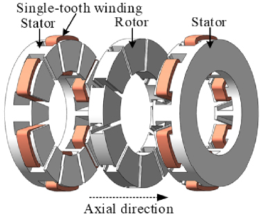
Figure 1: Three-phase double stator wide-and-narrow stator poles AFSRM structure.
The number of stator and rotor poles has a significant influence on the motor performance. The possible combination of stator and rotor poles for the NWS-AFSRM is:
| (1) |
where LCM means the least common multiple, Ns, Nr, and Nph represent the number of stator poles, rotor poles, and motor phases, Nsd and Nrd denote the number of poles of the stator and rotor of the unit motor.
Based on equation (1), the feasible stator/rotor pole combinations for three-phase, four-phase, and five-phase NWS-AFSRMs are readily obtained, as summarized in Table 1.
Table 1: Stator and rotor poles selection for NWS-AFSRM with different phase number
| Phase Number | Nsd | Nrd |
| 3 | 6 | 4, 5 |
| 4 | 8 | 5, 7 |
| 5 | 10 | 6, 7, 8, 9 |
According to Table 1, the feasible stator/rotor pole number combinations for three-phase NWS-AFSRMs are identified as 12/8 and 12/10, while potential combinations for four-phase NWS-AFSRMs are 16/10 and 16/14. Additionally, possible stator/rotor pole numbers for five-phase NWS-AFSRMs include 20/12, 20/14, 20/16, and 20/18.
Based on the principle of minimum reluctance, the phase excitation sequence for both the three-phase 12/8 and 12/10 NWS-AFSRMs is ABC. Similarly, the sequence for the four-phase 16/10 and 16/14 NWS-AFSRMs is ABCD. It can be observed that for both three-phase and four-phase NWS-AFSRMs, variations in rotor pole number do not result in new excitation sequences and the next conducting phase is always adjacent to the previous one.
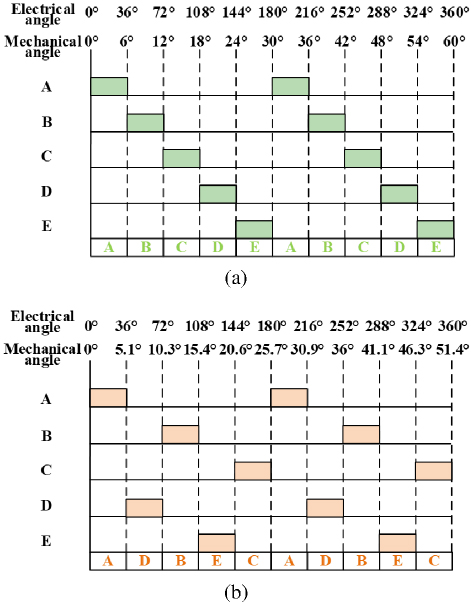
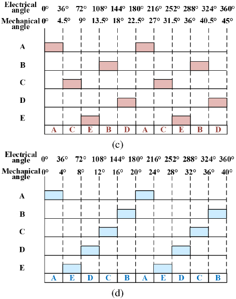
Figure 2: Excitation phase sequence of the four five-phase NWS-AFSRMs: (a) 20/12, (b) 20/14, (c) 20/16, and (d) 20/18.
However, for five-phase NWS-AFSRMs, differences in rotor pole number lead to the emergence of distinct excitation sequences. Figure 2 illustrates schematic diagrams of the phase excitation sequences for four five-phase NWS-AFSRMs with differing rotor pole numbers. As depicted in Fig. 2, the phase excitation sequence for the 20/12 five-phase NWS-AFSRM is ABCDE. For the 20/14, 20/16, and 20/18 machines, the excitation sequences are ADBEC, ACEBD, and AEDCB, respectively. It should be noted that for 20/12 and 20/18 motors, the next conducting phase is always adjacent to the preceding phase. Conversely, for 20/14 and 20/16 motors, the next conducting phase is non-adjacent to the preceding phase.
Furthermore, as a multiphase motor, the five-phase NWS-AFSRM offers advantages over conventional three-phase motors, such as lower overall cost of the drive system, reduced torque ripple, and enhanced reliability. Therefore, this paper focuses on the five-phase NWS-AFSRM to investigate the influence of rotor pole number and phase excitation sequence on its electromagnetic characteristics.
III. STATIC PERFORMANCE ANALYSIS
The main parameters of the five-phase NWS-AFSRM with four different rotor poles number are listed in Table 2. In order to achieve a fair comparison, these motors have the same dimensions externally, such as the same stator-rotor inner diameter, stator-rotor outer diameter, air gap length, axial length, and winding parameters.
Table 2: Parameters of the five-phase NWS-AFSRM
| Motor Parameters | Items | 20/12 | 20/14 | 20/16 | 20/18 |
| Rated voltage | V | 96 | 96 | 96 | 96 |
| Rated speed | r/min | 600 | 600 | 600 | 600 |
| Outer diameter | mm | 175 | 175 | 175 | 175 |
| Inner diameter | mm | 101 | 101 | 101 | 101 |
| Stator yoke length | mm | 7.5 | 7.5 | 7.5 | 7.5 |
| Stator pole length | mm | 32 | 32 | 32 | 32 |
| Stator slot width | mm | 10 | 10 | 10 | 10 |
| Rotor pole length | mm | 17 | 17 | 17 | 17 |
| Rotor slot width | mm | 19 | 15 | 14 | 11.5 |
| Air-gap length | mm | 0.4 | 0.4 | 0.4 | 0.4 |
| Winding coil turns per slot | / | 50 | 50 | 50 | 50 |
| Axial length | mm | 96.8 | 96.8 | 96.8 | 96.8 |
Figure 3: Finite element models of four five-phase NWS-AFSSRMs with different rotor poles number: (a) 20/12, (b) 20/14, (c) 20/16, and (d) 20/18.
Based on the parameters of the four motors in Table 2, their 3D finite element models were built in Altair flux software, as shown in Fig. 3.
A. Magnetic density characteristics
The magnetic density distribution map can reflect the magnetic saturation level of the motor’s stator and rotor cores. By applying an excitation current of 30 A to phase-C individually, the results of the magnetic density distribution of these four motors in the rotor aligned position and the unaligned position are obtained, as illustrated in Figs. 4 and 5.
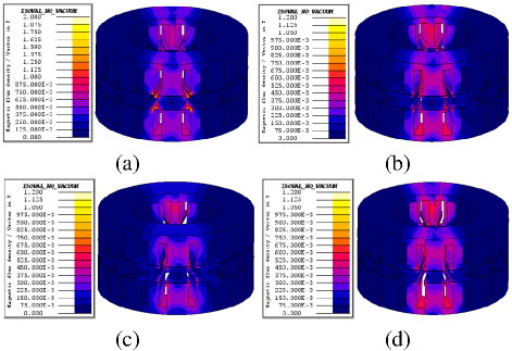
Figure 4: Magnetic density maps of the four five-phase NWS-AFSSRMs at the rotor unaligned position: (a) 20/12, (b) 20/14, (c) 20/16, and (d) 20/18.
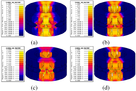
Figure 5: Magnetic density maps of the four five-phase NWS-AFSSRMs at the rotor aligned position: (a) 20/12, (b) 20/14, (c) 20/16, and (d) 20/18.
From Fig. 4, it can be observed that in the completely unaligned position, the magnetic flux density of the rotor segment core is small, and magnetic saturation occurs only at the rotor pole shoes. Meanwhile, there is little difference in the manifestation of magnetic density among the four motors, only slightly varying numerically. As found in Fig. 5, the magnetic flux density is uniformly distributed in the stator yoke, stator wide pole, stator narrow pole, and rotor block. Similar to the phenomenon in the unaligned position, the magneto-density clouds of the four motors in the aligned position are only slightly different in terms of the magneto-density intensity.
B. Inductance and torque characteristics
The inductance-angle-current and torque-angle-current characteristics can reflect the torque output capability of the NWS-AFSRM. Therefore, the phase self-inductance and static torque characteristics of four five-phase NWS-AFSRMs at different current levels (30 A and 60 A) are shown in Figs. 6 and 7.
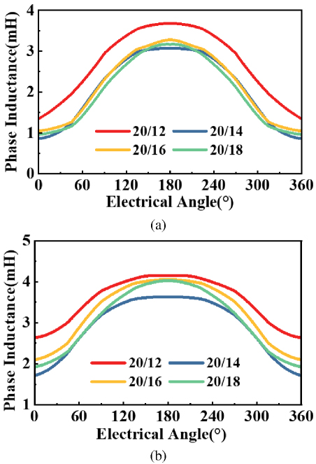
Figure 6: Phase self-inductance of the four five-phase NWS-AFSRMs at different excitation currents: (a) 30 A and (b) 60 A.
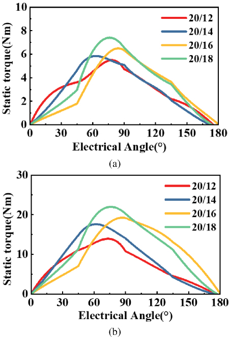
Figure 7: Static torque of the four five-phase NWS-AFSRMs at different excitation currents: (a) 30 A and (b) 60 A.
Table 3: Root mean square value of static torque for the four motors
| Excitation Current | 20/12 | 20/14 | 20/16 | 20/18 |
| 30 A | 3.417 | 3.539 | 3.713 | 4.257 |
| 45 A | 6.332 | 7.177 | 8.033 | 8.954 |
| 60 A | 8.702 | 10.527 | 12.414 | 13.275 |
| 75 A | 10.741 | 12.748 | 14.902 | 16.635 |
Root mean square values of static torque at different current levels (30 A, 45 A, 60 A, 75 A) are listed in Table 3. As observed, as the number of rotor poles increases, the root mean square of the static torque increases as well in different excitation current. It can be noted that the step angle decreases with increasing Nr as compared to motors with low rotor pole numbers. This leads to a decrease in the relative stator pole arc angle per revolution for the same multiphase conduction cycle. This means that more slot area is available for the excitation winding without reducing the maximum multiphase conduction cycle. Therefore, increasing the number of rotor poles can increase the static torque capacity of themotor.
IV. DYNAMIC PERFORMANCE ANALYSIS
In order to further analyze the dynamic performance of the motor, dynamic simulation models are established. It should be noted that the asymmetrical half-bridge converter circuit is employed for the power converter module, as depicted in Fig. 8.
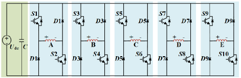
Figure 8: Five-phase asymmetric half-bridge power converter.
Figure 9 shows the dynamic torque waveforms of the four motors under the single pulse control method. The rotational speeds are set at 600 r/min and 1000 r/min. In order to ensure the fairness of the comparison, the turn-on and turn-off angles of the four motors are uniformly set at 0 and 36 electrical angles.
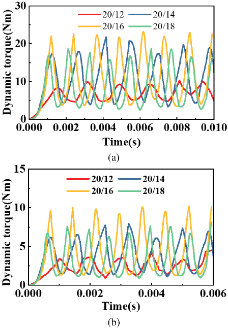
Figure 9: Dynamic torque of the four five-phase NWS-AFSRMs at different speeds: (a) 600 r/min and (b) 1000 r/min.
Table 4: Dynamic torque for the four motors
| Speed | 20/12 | 20/14 | 20/16 | 20/18 | |
| 600 r/min | Tmin | 4.538 | 3.396 | 3.163 | 2.449 |
| Tmax | 10.318 | 21.960 | 22.715 | 19.449 | |
| Tavg | 7.133 | 11.108 | 11.151 | 8.482 | |
| 1000 r/min | Tmin | 0.940 | 1.136 | 1.163 | 0.914 |
| Tmax | 4.636 | 8.024 | 10.133 | 8.049 | |
| Tavg | 2.582 | 3.997 | 4.365 | 3.274 |
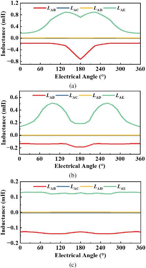
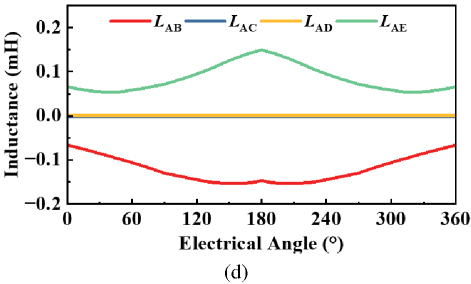
Figure 10: Comparison of mutual inductance for the four five-phase NWS-AFSRMs: (a) 20/12, (b) 20/14, (c) 20/16, and (d) 20/18.
From the results of Fig. 9 and Table 4, it is analyzed that the dynamic torque of the motor at the same number of ampere-turns is not increasing as the number of rotor poles increases. Among these four motors, the motor with the highest dynamic torque is 20/16 which is not the same as the static torque results.
The mutual inductance characteristics of the four motors are further analyzed in this paper. In NWS-AFSRM, mutual inductance refers to the ability of a current change in one phase winding to induce an effect in another phase winding. Generally, a lower mutual inductance value between phases corresponds to reduced interference between the respective windings [19-20]. Results of the mutual inductance of the four motors analyzed by FEA are presented in Fig. 10. Note that LAB, LAC, LAD, and LAE denote the mutual inductance values measured in windings B, C, D, and E, respectively, when current is applied to phase winding A.
As observed in Fig. 10, when excitation current is applied to phase A, the mutual inductances LAB and LAE are significant for all four motors, whereas LAC and LAD remain negligible. This phenomenon can be attributed to the structural characteristics of the NWS-AFSRM. Specifically, phase A shares auxiliary stator poles with both phase B and phase E. Consequently, excitation of phase A inevitably influences phases B and E to some degree. In contrast, the C-phase winding is separated from the A-phase winding by the B-phase winding and, similarly, the D-phase winding is separated from the A-phase winding by the E-phase winding. As a result, excitation of phase A has minimal effect on phases C and D. These observations are corroborated by the magnetic flux density distributions presented in Figs. 4 and 5.
As established in section II, the 20/12-pole and 20/18-pole NWS-AFSRMs exhibit ABCDE and AEDCB phase excitation sequences, respectively, where each subsequently energized phase is spatially adjacent to its predecessor. Due to the mutual coupling between adjacent phases, this configuration induces torque decay in the outgoing phase during commutation. Conversely, the ADBEC and ACEBD sequences of the 20/14-pole and 20/16-pole NWS-AFSRMs feature non-adjacent phase transitions, effectively avoiding inter-phase torque decay. In summary, among the four five-phase NWS-AFSRM configurations, the limited dynamic torque capability of the 20/12-pole and 20/18-pole machines is attributed to their significant mutual inductances LAB and LAE. These substantial mutual inductances adversely affect the dynamic torque performance. Conversely, the superior dynamic torque capability of the 20/14-pole and 20/16-pole configurations stems from their negligible mutual inductances LAC and LAD. This minimal mutual coupling enables them to maximize their inherent dynamic torque potential.
V. CONCLUSION
In this paper, the three-dimensional FEA approach is employed to investigate the influence of rotor poles number and phase commutation sequence on the electromagnetic performance of five-phase NWS-AFSRM. It was found that the static and dynamic electromagnetic torque of the four machines exhibited distinct characteristics, and potential underlying causes for this phenomenon were analyzed. Key findings are summarized as follows.
-
Phase excitation sequence varies with the rotor pole number. The sequences for the 20/12, 20/14, 20/16, and 20/18-pole configurations are ABCDE, ADBEC, ACEBD, and AEDCB, respectively.
-
Static torque under identical ampere-turn excitation increases monotonically with increasing rotor pole number. The static torque values, ranked from lowest to highest, correspond to the 20/12, 20/14, 20/16, and 20/18-pole machines.
-
In contrast, dynamic torque does not exhibit a monotonic increase with rotor pole number. The dynamic torque values, ranked from lowest to highest, correspond to the 20/12, 20/18, 20/14, and 20/16-pole machines.
-
Owing to the single-tooth wound structure and short flux path characteristics of the NWS-AFSRM, flux generated during the excitation of one phase adversely affects adjacent phases but minimally impacts non-adjacent phases. This phenomenon is identified as the primary reason for the superior dynamic torque of the 20/14-pole and 20/16-pole five-phase NWS-AFSRMs compared to the 20/12-pole and 20/18-pole counterparts.
Therefore, by designing appropriate combinations of stator slot number and rotor pole number in multiphase NWS-AFSRMs, the detrimental effects of mutual inductance between adjacent phases on motor performance can be mitigated. This provides a novel perspective for enhancing the performance of five-phase and higher-phase-count machines.
Note that the conclusions drawn in this study are based on the results of three-dimensional FEA. While this method represents a well-established standard in the electromagnetic design and analysis of electric machines, it is acknowledged that physical prototyping and experimental validation remain essential. Accordingly, future work will involve fabricating a prototype and establishing a test platform to experimentally verify the FEA results presented herein.
ACKNOWLEDGMENT
This work is supported by the National Natural Science Foundation of China International (regional) cooperation and exchange projects NSFC-RSF (W2412064), the Shenzhen Collaborative Innovation Special Plan International Cooperation Research Project (GJHZ20220913144400001), the General Research Project of Shenzhen Science and Technology Plan (JCYJ20220818100000001), the Jiangsu Funding Program for Excellent Postdoctoral Talent (2024ZB008), the China Postdoctoral Science Foundation (2024M763541), the 2022 China-CEEC University Joint Education Program (2022200), and the 2023 China-CEEC University Joint Education Program (2023304).
REFERENCES
[1] L. Ge, N. Du, J. Song, J. Zhang, Z. Fan, D. Zhang, and S. Song, “Advanced technology of switched reluctance machines in more electric aircraft: A review,” IEEE Trans. Power Electron., vol. 40, no. 1, pp. 195-216, Jan. 2025.
[2] K. Diao, G. Bramerdorfer, X. Sun, Z. Yang, and S. Han, “Multiobjective design optimization of a novel switched reluctance motor with unequal alternating stator yoke segments,” IEEE Trans. Transp. Electrif., vol. 9, no. 1, pp. 512-521, Mar. 2023.
[3] H. Torkaman, A. Ghaheri, and A. Keyhani, “Axial flux switched reluctance machines: A comprehensive review of design and topologies,” IET Electr. Power Appl., vol. 13, no. 3, pp. 310-321, Mar. 2019.
[4] M. Belhadi, G. Krebs, C. Marchand, et al., “Evaluation of axial SRM for electric vehicle application,” Electr. Power Syst. Res., vol. 148, pp. 155-161, July 2017.
[5] J. Ma, J. Li, H. Fang, Z. Li, Z. Liang, Z. Fu, L. Xiao, and R. Qu, “Optimal design of an axial-flux switched reluctance motor with grain-oriented electrical steel,” IEEE Trans. Ind. Appl., vol. 53, no. 6, pp. 5327-5337, Nov.-Dec. 2017.
[6] H. Arihara and K. Akatsu, “Basic properties of an axial-type switched reluctance motor,” IEEE Trans. Ind. Appl., vol. 49, no. 1, pp. 59-65, Jan.-Feb. 2013.
[7] Z. Xu, D.-H. Lee, and J.-W. Ahn, “Design and operation characteristics of a novel switched reluctance motor with a segmental rotor,” IEEE Trans. Ind. Appl., vol. 52, no. 3, pp. 2564-2572, May-June 2016.
[8] X. Sun, K. Diao, G. Lei, Y. Guo, and J. Zhu, “Study on segmented-rotor switched reluctance motors with different rotor pole numbers for BSG system of hybrid electric vehicles,” IEEE Trans. Veh. Technol., vol. 68, no. 6, pp. 5537-5547, June 2019.
[9] B. C. Mecrow, E. A. El-Kharashi, J. W. Finch, and A. G. Jack, “ Segmental rotor switched reluctance motors with single-tooth windings,” IEE Proc.-Electr. Power Appl., vol. 150, no. 5, Sep. 2003.
[10] X. Y. Ma, G. J. Li, G. W. Jewell, and Z. Q. Zhu, “Recent development of reluctance machines with different winding configurations, excitation methods, and machine structures,” CES Transactions on Electrical Machines and Systems (TEMS), vol. 2, no. 1, pp. 82-92, Mar. 2018.
[11] T. Husain, W. Uddin, and Y. Sozer, “Performance comparison of short-pitched and fully pitched switched reluctance machines over wide speed operations,” IEEE Trans. Ind. Appl., vol. 54, no. 5, pp. 4278-4287, Sep.-Oct. 2018.
[12] E. Cosoroaba, E. Bostanci, Y. Li, et al., “Comparison of winding configurations in double-stator switched reluctance machines,” IET Electr. Power Appl., vol. 11, no. 8, pp. 1407-1415, Sep. 2017.
[13] A. Labak and N. C. Kar, “Designing and prototyping a novel five-phase pancake-shaped axial-flux SRM for electric vehicle application through dynamic FEA incorporating flux-tube modeling,” IEEE Trans. Ind. Appl., vol. 49, no. 3, pp. 1276-1288, May-June 2013.
[14] R. Madhavan and B. G. Fernandes, “Axial flux segmented SRM with a higher number of rotor segments for electric vehicles,” IEEE Trans. Energy Convers., vol. 28, no. 1, pp. 203-213, Mar. 2013.
[15] R. Madhavan and B. G. Fernandes, “Performance improvement in the axial flux-segmented rotor-switched reluctance motor,” IEEE Trans. Energy Convers., vol. 29, no. 3, pp. 641-651, Sep. 2014.
[16] W. Sun, Q. Li, L. Sun, L. Zhu, and L. Li, “Electromagnetic analysis on novel rotor-segmented axial-field SRM based on dynamic magnetic equivalent circuit,” IEEE Trans. Magn., vol. 55, no. 6, pp. 1-5, June 2019.
[17] W. Sun, Q. Li, L. Sun, and L. Li, “Development and investigation of novel axial-field dual-rotor segmented switched reluctance machine,” IEEE Trans. Transp. Electrif., vol. 7, no. 2, pp. 754-765, June 2021.
[18] F. Yu, H. Chen, W. Yan, V. Pires, J. Martins, P. Rafajdus, A. Musolino, L. Sani, M. Aguirre, M. Saqib, M. Orabi, and X. Li, “Design and multiobjective optimization of a double-stator axial flux SRM with full-pitch winding configuration,” IEEE Trans. Transp. Electrif., vol. 8, no. 4, pp. 4348-4364, Dec. 2022.
[19] E. S. Sanches and J. A. Santisteban, “Mutual inductances effect on the torque of an axial magnetic flux switched reluctance motor,” IEEE Latin America Trans., vol. 13, no. 7, pp. 2239-2244, July 2015.
[20] J. Ye, B. Bilgin, and A. Emadi, “Elimination of mutual flux effect on rotor position estimation of switched reluctance motor drives,” IEEE Trans. Power Electron., vol. 30, no. 3, pp. 1499-1512, Mar. 2015.
BIOGRAPHIES

Fengyuan Yu received the Ph.D. degree from the School of Electrical Engineering, China University of Mining and Technology, Xuzhou, China, in 2023. Since 2023, he has been a Post-Doctoral Researcher with the China University of Mining and Technology. His research interests include switched reluctance drive, special motor design, power converters, and motor control.

Xing Wang received the B.S. and M.S. degrees from China University of Mining and Technology, Xuzhou, China, in 1996 and 1999, respectively. Her research interests include switched reluctance drive, electric vehicle, electric traction, wind power generator, power converters, and motor control.

Hao Chen received his B.S. and Ph.D. degrees from the Department of Automatic Control, Nanjing University of Aeronautics and Astronautics, Nanjing, China, in 1991 and 1996, respectively. Since 1996, he has been with China University of Mining and Technology, where he is currently a Full Professor with the School of Electrical Engineering. His research interests include motor control, linear launcher, electric vehicles, electric traction, servo drives, and wind power generator control.

Wenju Yan received the B.S. and Ph.D. degrees from the China University of Mining and Technology, Xuzhou, China, in 2013 and 2018, respectively. Since 2018, he has been with China University of Mining and Technology, where he is currently an Associate Professor with the School of Electrical Engineering. His research interests include electric vehicles, electric traction, iron loss analysis, and motor design.

Hongwei Yang is pursuing his master’s degree in electrical engineering at China University of Mining and Technology, Xuzhou, China. His current research interests include electric vehicles, electric traction, and special motor design.

Popov Stanislav Olegovich received the M.S. degree from in the field of electric power plants and automation of power systems in 2008, and the PhD degree of Technical Sciences associate professor Institute of Energy, working from 2008 to the present in SPBSTU.

Bodrenkov Evgenii Alexandrovich received the B.S. and M.S. degrees from Federal State Budgetary Educational Institution of Higher Education, Amur State University, and the Ph.D. degrees from Federal State Autonomous Educational Institution of Higher Education, Peter the Great St. Petersburg Polytechnic University.

Nurkhat Zhakiyev is a senior researcher and associate professor with a Ph.D. in the field of physics and currently serves as the head of the Department of Science and Innovation at the Astana University of Information Technology, Kazakhstan. He has nearly a decade of research experience in computational modeling of energy systems and physical processes, with a focus on data science in energy and environmental economics and climate change mitigation analysis. He started his career in 2007 as a junior researcher at West Kazakhstan State University, then rose through the ranks in various higher education institutions and research institutes in Astana, where he gained extensive experience in research and project management. He has worked as a principal researcher or co-researcher on projects funded by the Ministry of Science and Higher Education of Kazakhstan, the Royal Academy of Engineering, the British Council and other institutions in various fields such as low carbon development, greenhouse gas emission forecasting, energy efficiency solutions and more.

Yassen Gorbounov received his B.S., M.S., and Ph.D. degrees from the Sofia University of Technology, Sofia, Republic of Bulgaria, in 2002, 2004, and 2013, respectively. Since 2017, he has been working as an Associate Professor at the Sofia University of Technology. His current research interests include power electronics and the mining industry.
ACES JOURNAL, Vol. 40, No. 9, 883–892
doi: 10.13052/2024.ACES.J.400909
© 2025 River Publishers