Modeling and Analysis of Equivalent Magnetic Network Model for Novel Asymmetric Rotor Permanent Magnet-assisted Synchronous Reluctance Motor
Hao Chen, Ziqiang Wei, Xing Wang, Shudong Hou, Antonino Musolino, Murat Shamiyev, Pulatov Abror Abidovich, Emmanuel Karapidakis, Aris Dimeas, and Sherif Moussa
1Shenzhen Research Institute
China University of Mining and Technology, Shenzhen 515100, China
hchen@cumt.edu.cn, 3512@cumt.edu.cn
2School of Electrical Engineering
China University of Mining and Technology, Xuzhou 221116, China
tb23230015p41@cumt.edu.cn
3Nexus Intelligent Equipment (Zhejiang) Co. Ltd.
Zhejiang, China
njdr2007@126.com
4Department of Energy, System, Territory and Construction Engineering (DESTEC)
University of Pisa, 56122 Pisa, Italy
antonino.musolino@unipi.it
5Tashkent State Technical University
Tashkent City, Republic of Uzbekistan
antonino.musolino@unipi.it, Hello_murat@mail.ru, abrorobidovich@mail.ru
6School of Engineering
Hellenic Mediterranean University (HMU),
Estavromenos Campus, 71004 Heraklio, Crete, Greece
karapidakis@hmu.gr
7Athens National University of Technology
Greece
adimeas@power.ece.ntua.gr
8School of Engineering
Canadian University, Sheikh Zayed Road, 117781 Dubai, UAE
smoussa@cud.ac.ae
Submitted On: November 30, 2024; Accepted On: September 2, 2025
ABSTRACT
This paper presents a novel asymmetric rotor permanent magnet-assisted synchronous reluctance motor (NAR-PMa-SynRM) designed to enhance torque output and reduce torque ripple by employing unconventional methods compared to traditional approaches where permanent magnets are embedded within magnetic barriers. In this design, tile-shaped permanent magnets are embedded along the rotor d-axis, coupled with an asymmetric magnetic barrier structure. To streamline the motor design process, a nonlinear equivalent magnetic network (EMN) model tailored to the distinctive structure of the NAR-PMa-SynRM is proposed. However, modeling the complex magnetic barrier structure poses a significant challenge in magnetic network modeling. To address this challenge, an effective method for representing the magnetic barriers equivalently is proposed to enhance modeling accuracy. Finally, the effectiveness of the proposed equivalent barrier method and magnetic network model is validated by comparing air gap magnetic flux density results obtained from finite element and magnetic network simulations.
Index Terms: Equivalent magnetic network, finite element analysis, permanent magnet-assisted synchronous reluctance motor.
I. INTRODUCTION
In recent years, global initiatives such as “carbon neutrality” and “peak carbon emissions” have driven advancements in carbon reduction technologies, among which high-efficiency, high-power-density electric motors play a pivotal role in sectors like new energy vehicles, industrial drives, and compressors [1–3]. Rare-earth permanent magnet (PM) motors have emerged as key solutions in this context; however, their sustainability is constrained by the volatility of rare-earth supply chains and associated cost instabilities, given rare-earths’ strategic resource status [4].
To mitigate reliance on rare-earth PM materials while maintaining performance and reducing costs, synchronous reluctance motors (SynRMs) have gained attention. Characterized by rotor structures free of windings and PMs, SynRMs generate torque exclusively via reluctance effects enabled by their multi-layer air gap design, offering advantages such as low manufacturing costs, temperature insensitivity, and robust transient overload capability [5–8]. Nevertheless, their inherent limitations, including low torque output and poor power factor, often restrict their applicability in high-performance scenarios.
To address these drawbacks, permanent magnet-assisted synchronous reluctance motors (PMa-SynRMs) have been developed by strategically embedding moderate amounts of PMs within the multi-layer air gap structure of SynRMs. This integration combines PM-derived electromagnetic torque with reluctance torque, achieving a balance between low cost and enhanced performance [9–11]. Notably, PMa-SynRMs exhibit exceptional power density in high-speed applications through optimized structural design, alongside improved efficiency and reduced torque ripple; attributes that make them well-suited for electric vehicle propulsion [12–14]. Extensive research has further validated their effectiveness in such applications, yielding significant technical information [15–18]. In [19], the SynRM of the rotor structure with flux barriers is proposed, and the two types of rotors are compared using 2-D finite-element analysis. The results show that the rotor structure with flux barriers is more effective in generating torque and suspension force. Reference [20] highlighted the suitability of external rotor PMa-SynRMs for hub motors in electric vehicles, successfully integrating them into the two-wheel drive systems of electric cars.
This paper introduces a novel asymmetric rotor permanent magnet-assisted synchronous reluctance motor (NAR-PMa-SynRM), which integrates embedded surface-mounted permanent magnet motor (Embedded-SPM) and SynRM technologies in a coherent manner. By employing mechanical rotation and an asymmetric rotor structure, the motor effectively harnesses both electromagnetic torque and reluctance torque. In this configuration, tile-shaped PMs are embedded on the rotor surface, akin to surface-mounted PM motors. The rotor core features an asymmetric design of magnetic barriers, where each layer of barriers can be independently designed in terms of angle and length.
The work presented in this paper is at the preliminary design stage of the NAR-PMa-SynRM. A equivalent magnetic network (EMN) model tailored to the specific structure of NAR-PMa-SynRM is proposed, alongside a simplified equivalent method during the modeling process. Results from the EMN model align closely with finite element analysis (FEA) results, validating the effectiveness of the proposed equivalent method and the accuracy of the EMN model. Based on the EMN model, an initial electromagnetic design of the motor is conducted. FEA results indicate that compared to Embedded-SPM, NAR-PMa-SynRM demonstrates superior output capability. In section II, the structure and key parameters of NAR-PMa-SynRM are presented. Section III outlines the modeling and computational methodologies of the EMN model and equivalent methods tailored specifically for NAR-PMa-SynRM. These approaches are aimed at accurately capturing the motor’s electromagnetic characteristics. Validation of these methods against FEA results demonstrates their reliability and effectiveness. In section IV, the structure preliminarily designed based on the EMN model is implemented in a finite element model, where both no-load characteristics and rated output performance are analyzed. Finally, in section V, a summary of the paper is presented.
II. DESCRIPTION OF NOVEL ASYMMETRIC ROTOR PERMANENT MAGNET-ASSISTED SYNCHRONOUS RELUCTANCE MOTOR
The NAR-PMa-SynRM integrates elements from Embedded-SPM and SynRM. Unlike conventional PMa-SynRM, the NAR-PMa-SynRM adopts a configuration where tile-shaped PMs are embedded along the rotor’s d-axis, and the rotor core’s magnetic barriers feature an asymmetric design. These innovations aim to enhance torque output and minimize torque ripple. Figure 1 depicts a two-dimensional cross-section of the NAR-PMa-SynRM rotor structure. Here, the radial direction with the least reluctance is identified as the d-axis, whereas the radial direction along the centerline of the magnetic barrier is termed the q-axis. A mechanical angular offset of /P is present between the PMs and the rotor’s d-axis.
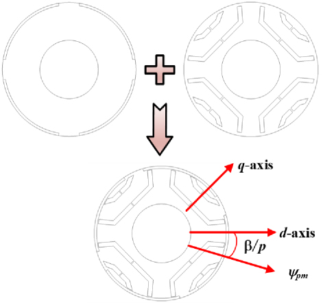
Figure 1: Rotor structure of NAR-PMa-SynRM.
Table 1: Design requirements of the machine
| Parameter | Value |
| Rated power (kW) | 5.5 |
| Rated speed (r/min) | 3000 |
| DC bus voltage (V) | 380 |
| Efficiency (%) | 90 |
| Outer diameter (mm) | 175 |
The design criteria for the NAR-PMa-SynRM are outlined in Table 1, taking into consideration the power, spatial, and voltage requirements of electric vehicle drive systems. Given constraints on enclosure size and installation space, the stator core has an outer diameter of 175 mm. Moreover, the power system mandates a 380 V DC bus voltage to accommodate the machine’s high-power output needs. Table 2 presents the principal parameters of the PM synchronous motor designed in accordance with these specifications. The machine features 36 slots and 4 poles, maintaining a rated current density of 10 A/mm2 in preliminary designs. Initial design simulations using this current density suggest compliance with the requirements specified in Table 1.
The stator core and rotor core are assembled using stacked laminations of M350-50A silicon steel, known for its excellent electrical conductivity. NdFe35 magnets are utilized for the PM material. The stator windings employ 0.8 mm enamel-coated wire, with 16 turns per slot, utilizing a short-pitch winding configuration with a coil span of 8.
Table 2: Main parameters of the NAR-PMa-SynRM
| Parameter | Value |
| Slot/Pole number | 36/4 |
| Stator outer diameter (mm) | 175 |
| Stator inner diameter (mm) | 93.5 |
| Core length (mm) | 50 |
| Conductor diameter (mm) | 0.8 |
| Rated current density (A/mm2) | 10 |
| Turns | 16 |
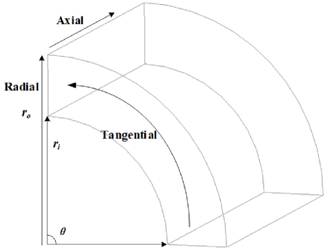
Figure 2: Schematic diagram of typical flux directions.
III. EQUIVALENT MAGNETIC NETWORK MODELING
Due to the motor’s structural symmetry about the origin center, an EMN model of a 1-pair pole, 18-slot motor is established to reduce computational complexity and enhance computational speed. Based on the motor’s flux distribution, three typical equivalent magnetic conductivities—axial, tangential, and radial—are determined. Diagrams illustrating these three typical flux directions are presented in Fig. 2, accompanied by their respective magnetic conductivity calculation formulas:
| (1) |
| (2) |
| (3) |
where Gaxial is the axial permeability, Gradial is the radial permeability, Gtangential is the tangential permeability, l is the axial length of the unit, ro is the outer diameter, ri is the inner diameter, Am is the area of the unit, is the arc of the center angle of the unit, is the relative permeability.
In the magnetic network method, the calculation of equivalent magnetic potential sources for magnetic field sources is divided into two parts: the armature reaction magnetic potential source generated by the current and the PM magnetic potential source generated by the PM. For the unloaded operation of a PM SynRM, only the PM provides the magnetic potential source, as the armature current is negligible (0 A) and does not contribute to the magnetic potential source. Thus, the calculation focuses solely on the equivalent magnetic potential source of the PM. Figure 3 depicts the model diagram of unit permanent magnet magnetic network.
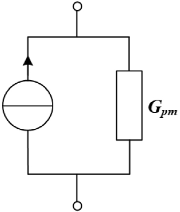
Figure 3: Model diagram of unit permanent magnet magnetic network.
The magnitude of the equivalent magnetic flux source of the PM and its intrinsic magnetic conductivity is expressed as follows, with the PM’s intrinsic magnetic conductivity assumed to be linear:
| (4) |
| (5) |
where is the PM equivalent flux source, Gpm is the self-permeability of a PM, Br is the residual magnetic density of a PM, wpm is the width of a PM, lpm is the axial length of a PM, hpm is the thickness of a PM, is the vacuum permeability, is relative permeabilityof a PM.
A. Magnetic barrier equivalent method
In the rotor structure of the NAR-PMa-SynRM, the magnetic barriers are dual-layered U-shaped, with slight variations in angles between the layers and between left and right sides. During magnetic network modeling, ensuring accuracy for the barriers and surrounding magnetic resistances poses challenges. Therefore, this paper proposes an effective method for barrier equivalence, significantly enhancing modeling precision, and meeting modeling requirements primarily through equations (1-3).
For simplifying the magnetic network modeling of the rotor structure, this paper equivalently models the magnetic barriers, central column, and surrounding iron core sections as sector-shaped structures. Each central column of the magnetic barriers per layer is taken as the equivalent center, transforming the same layer of magnetic barriers into sector rings around the motor’s center circle. The schematic diagrams of the magnetic barriers before and after equivalence are depicted in Fig. 4. The specific calculations for equivalence are detailed as follows:
| (6) |
| (7) |
| (8) |
| (9) |
| (10) |
| (11) |
| (12) |
| (13) |
| (14) |
| (15) |
where Ro_1 is the outside radius of the first layer of magnet barriers, Ri_1 is the inside radius of the first layer of magnet barriers, Rb_r1 is the radius of the inner side of the transverse barrier, Rb_r2 is the radius of the outer side of the transverse barrier, t_core is the thickness between the first layer and second layer of magnet barriers, rib_w1 and rib_w2 are the widths of the first- and second-layer center columns, respectively, 1 to 8 are the radians of each part of the magnetic barrier.
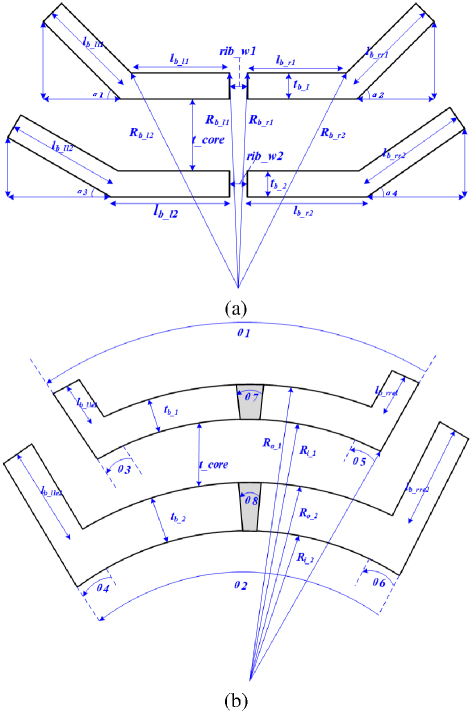
Figure 4: Equivalent schematic of the rotor magnetic barrier: (a) before equivalence and (b) after equivalence.
In the research on rotor magnetic barrier equivalence, [21] focuses on multi-layer flux barriers in symmetric SynRMs, adopting a topology partition method to decompose barriers into fan-shaped subdomains and integrating an equivalent current method to simulate saturation, though its partition process is relatively complex and primarily suited for symmetric structures. Reference [22] targets two-layered rectangular barriers in symmetric delta-type IPM motors, reconstructing them into equivalent spoke-type magnets via magnetic equivalent circuits and equivalent air-gap functions, which relies heavily on material parameter calibration. In contrast, this paper addresses dual-layer U-shaped asymmetric magnetic barriers in NAR-PMa-SynRM by equivalently transforming barriers, central columns, and surrounding iron cores into sector rings centered on the central column. This method directly preserves the original asymmetric structural features, with validation showing good consistency in back-EMF, air-gap flux density, and their harmonics with the initial model, achieving a better balance between simplicity and accuracy, especially in adapting to asymmetric structures.
The equivalent rotor structure of the NAR-PMa-SynRM, as shown in Fig. 4, can be modeled using sectorial units for the entire rotor section in magnetic network analysis. Figure 5 depicts the no-load back electromotive force (EMF) waveforms of the motor before and after equivalence at rated speed (3000 r/min). Specifically, the amplitude of the line back-EMF prior to equivalence is 158 V, while that after equivalence is 152 V, resulting in an error of only 3.8%. In terms of harmonics, the 3rd and 5th harmonics are slightly reduced, while the 7th and 9th harmonics are slightly increased. It is observed that the amplitude of the equivalent EMF decreases slightly, while maintaining good sinusoidal characteristics. Figure 6 presents the Fourier decomposition of the no-load EMF before and after equivalence, revealing a reduction in fundamental, 3rd, and 5th harmonic amplitudes after equivalence, with an increase in seventh and ninth harmonicamplitudes.
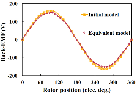
Figure 5: Back-EMF waveforms of the motor before and after equivalence at rated speed (3000 r/min).
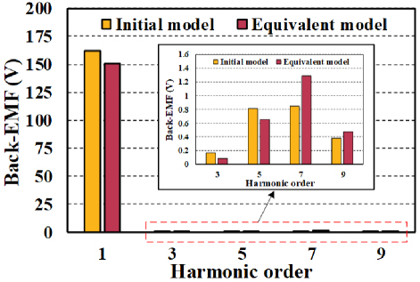
Figure 6: Harmonic component of back-EMFs.
Figure 7 illustrates the air-gap flux density of the motor before and after equivalence at rated speed (3000 r/min). The waveform of air-gap flux density remains largely consistent before and after equivalence, with a slight decrease in flux density amplitude after equivalence, within acceptable error margins. Figure 8 shows the Fourier decomposition of the air-gap flux density of the motor before and after equivalence.
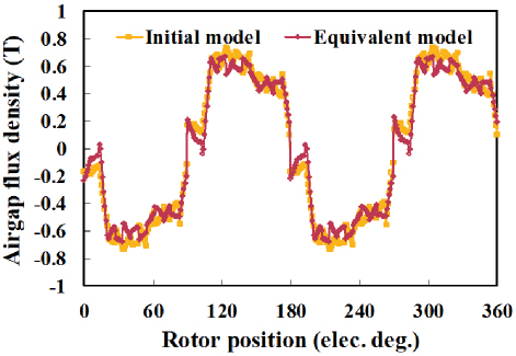
Figure 7: Airgap flux density of the motor before and after equivalence.
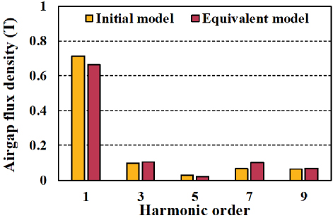
Figure 8: Harmonic component of airgap flux density.
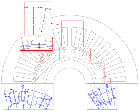
Figure 9: Schematic representation of the cross-section of the EMN model.
In terms of the harmonic distribution of the overall waveform, the equivalent model and the initial model show a high degree of consistency in harmonic trends (a decrease in low-order harmonics and an increase in high-order harmonics). Combined with the controllable attenuation degree of the fundamental wave, it further verifies the effectiveness of the simplified modeling method in preserving the core characteristics of the magnetic network.
Figure 9 presents a cross-section of the magnetic network model of NAR-PMa-SynRM. Figure 9 illustrates the magnetic circuit connections of selected magnetic network units.
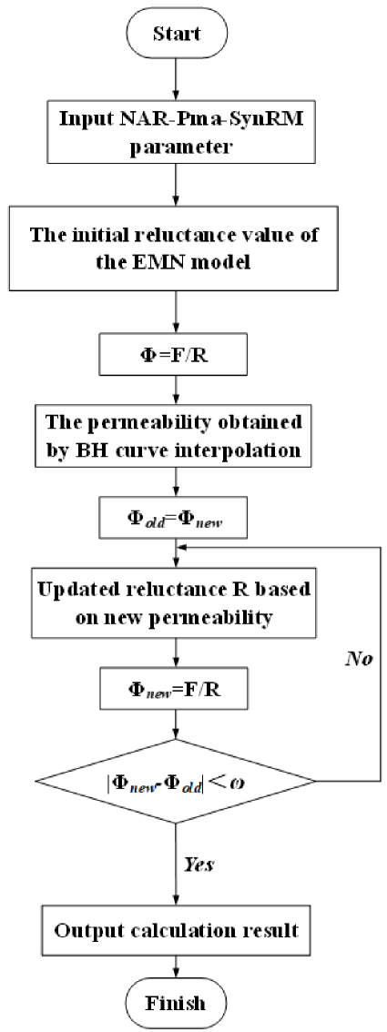
Figure 10: Flow chart of EMN model method calculation.
It is evident that the magnetic circuit structure of the stator core is relatively straightforward, whereas that of the rotor is more intricate. The PMs are not perfectly aligned with the rotor d-axis, resulting in certain magnetic bridges being in close proximity to the air gap. This complex magnetic barrier structure causes significant differences in the magnetic paths of the rotor in the radial and tangential directions. The EMN model is built through three key steps, with clear boundary conditions defined for credibility:
(1) Break down continuous magnetic flux paths into distinct segments. (2) For each segment, calculate magnetic reluctance based on its length, cross-sectional area, and material permeability. PMs are treated as equivalent magnetomotive force sources. (3) Construct the network using nodes (junctions where flux paths meet) and branches (combining reluctance segments and magnetomotive force sources). The network follows basic magnetic laws: flux is conserved at nodes (incoming flux equals outgoing flux), and the total magnetomotive force in a closed loop balances the magnetic “drops” across reluctance segments.
Flux remains continuous at material interfaces (e.g., between iron cores and air gaps). Nodes within high-permeability iron cores are considered equipotential (minimal magnetic potential variation). Symmetry constraints (if the system is symmetric) simplify the network by enforcing balanced flux distribution at symmetry axes.
The principles of the EMN circuit were employed to develop a corresponding DC circuit model in Simulink for computing the two-dimensional EMN model, as illustrated in Fig. 10. During the no-load condition of the motor, an iterative method was employed to calculate the magnetic flux through each magnetic reluctance, thereby determining the operational state of the entire motor magnetic circuit. The approach involved initially assigning predefined values to each reluctance and subsequently allocating these values to the corresponding resistances in the Simulink EMN model. Through Simulink simulation, the flux through each reluctance was computed, and these values were returned to the MATLAB workspace as predefined flux values. Using these flux values, the magnetic induction intensity of each partition cell was calculated, followed by redefining the permeability of each unit through interpolation of the magnetization curve.
The reluctance values of each partition unit were recalculated and assigned to the corresponding resistances in the Simulink EMN model. Subsequent simulation through Simulink computed the flux through each reluctance and returned these values to the MATLAB workspace. The computed flux values were compared with the predefined values, and if the difference fell within the specified reference range, the computation met the requirements and thus concluded. Otherwise, the magnetic flux was iteratively adjusted using the Atiken acceleration convergence algorithm until the desired accuracy was achieved.
Figure 11 displays the air-gap magnetic flux density results computed by the EMN model. The amplitude of the air-gap magnetic flux density is 0.643. The initial model yielded an air-gap magnetic flux density amplitude of 0.712, while the equivalent model produced 0.664. The error in the air-gap magnetic flux density amplitude is within a reasonable range. However, due to the limited number of sampling points, the fitted curve does not perfectly coincide with the curve of the original model. A finer sampling method would yield a more accurate curve but at the expense of increased computational time. The above results prove the effectiveness of the EMN model.
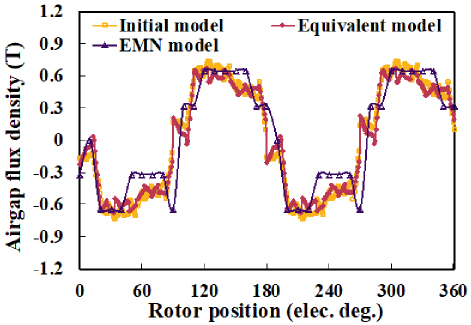
Figure 11: Results of air gap flux density calculated by EMN model.
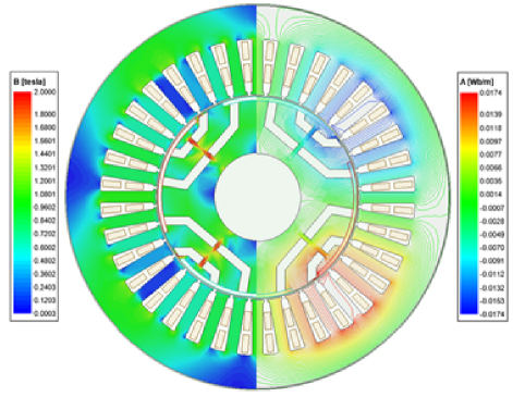
Figure 12: No-load magnetic field distribution of the preliminarily designed NAR-PMa-SynRM.
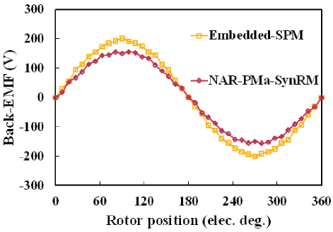
Figure 13: No-load line back-EMF of the preliminarily designed NAR-PMa-SynRM.
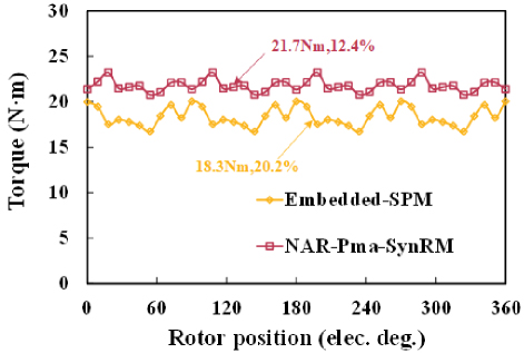
Figure 14: Output torque of the preliminary designed NAR-PMa-SynRM is at the rated operating condition.
IV. FINITE ELEMENT ANALYSIS
Building upon the EMN model, a preliminary design of the motor’s stator-rotor structure is conducted to facilitate efficient parametric iterations during the conceptual design phase. Figure 12 presents the no-load magnetic field distribution of the motor. As visualized, magnetic flux emanating from the stator teeth travels through the airgap, penetrates the rotor pole shoes, and converges at the rotor magnetic bridges, where significant magnetic saturation occurs. This saturation arises due to the narrow width of the magnetic bridges, which increases local magnetic reluctance and concentrates the flux density in these regions. Given that the magnetic bridges are made of electrical steel (with a saturation flux density of approximately 1.8T), the concentrated flux easily drives these areas into saturation even under no-loadconditions.
Figure 13 illustrates the open-circuit back-EMF waveforms of the Embedded-SPM and NAR-PMa-SynRM. It can be observed that both motors exhibit well-maintained sinusoidal characteristics in their EMF waveforms. The amplitude of the back-EMF in NAR-PMa-SynRM is slightly lower compared to that in Embedded-SPM, attributable to mechanical rotation of the PMs.
Figure 14 depicts the torque waveform of the motor under rated conditions. Leveraging both electromagnetic torque and reluctance torque effectively, NAR-PMa-SynRM exhibits an average torque increase of 18.6% compared to Embedded-SPM, with a reduction in torque ripple by 7.8%.
V. CONCLUSION
This paper introduces a novel asymmetric rotor permanent magnet-assisted synchronous reluctance motor (NAR-PMa-SynRM), integrating embedded surface-mounted PM technology with SynRM principles to enhance motor output performance by effectively leveraging both electromagnetic and reluctance torque. The focus of this study lies in the preliminary design phase of the motor, which includes the development of a magnetic network model tailored specifically for NAR-PMa-SynRM. To simplify the modeling process and improve the accuracy of rotor magnetic circuit equivalences, a simplified equivalent method is proposed. The computational results of the equivalent magnetic network (EMN) model align closely with finite element analysis (FEA) results, validating the effectiveness of the proposed EMN model and equivalent methods. Subsequently, based on the preliminary design outcomes derived from the EMN model, a finite element model is established. The results demonstrate that NAR-PMa-SynRM achieves an average torque increase of 18.6% compared to Embedded-SPM, with a reduction in torque ripple by 7.8%.
This study demonstrates the substantial potential of NAR-PMa-SynRM in terms of output performance. Future efforts in refining the design of NAR-PMa-SynRM will involve detailed parameterization, multi-objective optimization, and the integration of multi-physics coupling for equivalent stress and thermal management.
ACKNOWLEDGEMENT
This work was supported by the 2023 China-CEEC University Joint Education Program (2023304).
REFERENCES
[1] X. Zhou, X. Zhu, W. Wu, Z. Xiang, Y. Liu, and L. Quan, “Multi-objective optimization design of variable-saliency-ratio PM motor considering driving cycles,” IEEE Transactions on Industrial Electronics, vol. 68, no. 8, pp. 6516-6526, Aug. 2021.
[2] A. M. El-Refaie, “Fractional-slot concentrated-windings synchronous permanent magnet machines: opportunities and challenges,” IEEE Transactions on Industrial Electronics, vol. 57, no. 1, pp. 107-121, Jan. 2010.
[3] K. T. Chau, C. C. Chan, and C. Liu, “Overview of permanent-magnet brushless drives for electric and hybrid electric vehicles,” IEEE Transactions on Industrial Electronics, vol. 55, no. 6, pp. 2246-2257, June 2008.
[4] S. Zheng, X. Zhu, L. Xu, Z. Xiang, L. Quan, and B. Yu, “Multi-objective optimization design of a multi-permanent-magnet motor considering magnet characteristic variation effects,” IEEE Transactions on Industrial Electronics, vol. 69, no. 4, pp. 3428-3438, Apr. 2022.
[5] A. Vagati, “The synchronous reluctance solution: A new alternative in ac drives,” in Proc. 20th Int. Conf. Ind. Electron., Control Instrum., vol. 1, pp. 1-13, Sep. 1994.
[6] A. Boglietti, A. Cavagnino, M. Pastorelli, and A. Vagati, “Experimental comparison of induction and synchronous reluctance motors performance,” in Proc. 14th IAS Annu. Meet. Conf. Rec. Ind. Appl. Conf., vol. 1, pp. 474-479, 2005.
[7] A. T. de Almeida, F. J. T. E. Ferreira, and G. Baoming, “Beyond induction motors—Technology trends to move up efficiency,” IEEE Transactions on Industry Applications, vol. 50, no. 3, pp. 2103-2114, May/June 2014.
[8] R. R. Moghaddam and F. Gyllensten, “Novel high-performance SynRM design method: An easy approach for a complicated rotor topology,” IEEE Transactions on Industrial Electronics, vol. 61, no. 9, pp. 5058-5065, Sep. 2014.
[9] M. Xu, G. Liu, Q. Chen, J. Ji, and W. Zhao, “Design and optimization of a fault tolerant modular permanent magnet assisted synchronous reluctance motor with torque ripple minimization,” IEEE Trans. Ind. Electron., vol. 68, no. 9, pp. 8519-8530, Sep. 2021.
[10] M. Z. Islam, A. Arafat, S. S. R. Bonthu, and S. Choi, “Design of a robust five-phase ferrite-assisted synchronous reluctance motor with low demagnetization and mechanical deformation,” IEEE Trans. Energy Convers., vol. 34, no. 2, pp. 722-730, June 2019.
[11] S. Ciceo, F. Chauvicourt, B. Varaticeanu, J. Gyselinck, and C. Martis, “PMASynRM late design-stage rotor shape NVH optimization,” in Proc. IEEE Int. Conf. Elect. Mach., pp. 278-283, 2020.
[12] G. Gallicchio, M. D. Nardo, M. Palmieri, A. Marfoli, M. Degano, C. Gerada, and F. Cupertino, “High speed permanent magnet assisted synchronous reluctance machines - Part I: A general design approach,” IEEE Transactions on Energy Conversion, vol. 37, no. 4, pp. 2556-2566, Dec. 2022.
[13] Y.-H. Jeong, K. Kim, Y.-J. Kim, B.-S. Park, and S.-Y. Jung, “Design characteristics of PMa-SynRM and performance comparison with IPMSM based on numerical analysis,” in 2012 XXth International Conference on Electrical Machines, Marseille, France, pp. 164-170, 2012.
[14] S. S. Maroufian and P. Pillay, “Design and analysis of a novel pm-assisted synchronous reluctance machine topology with AlNiCo magnets,” IEEE Transactions on Industry Applications, vol. 55, no. 5, pp. 4733-4742, Sep.-Oct. 2019.
[15] T. Teratani, K. Kuramochi, H. Nakao, T. Tachibana, K. Yagi, and S. Abou, “Development of Toyota mild hybrid system (THS-M) with 42V power net,” in IEEE International Electric Machines and Drives Conference 2003 (IEMDC’03), Madison, WI, USA, vol. 1, pp. 3-10, 2003.
[16] I. Boldea, “Automobile electrification trends: A review,” in 2007 International Aegean Conference on Electrical Machines and Power Electronics, Bodrum, Turkey, pp. 369-377, 2007.
[17] L. Tutelea, A. M. Popa, and I. Boldea, “50/100 kW, 1350-7000 rpm (600 Nm peak torque, 40 kg) PM assisted reluctance synchronous machine: Optimal design with FEM validation and vector control,” in 2014 International Conference on Optimization of Electrical and Electronic Equipment (OPTIM), Bran, Romania, pp. 276-283, 2014.
[18] M. Ferrari, N. Bianchi, and E. Fornasiero, “Analysis of rotor saturation in synchronous reluctance and pm-assisted reluctance motors,” IEEE Transactions on Industry Applications, vol. 51, no. 1, pp. 169-177, Jan.-Feb. 2015.
[19] M. Takemoto, K. Yoshida, N. Itasaka, Y. Tanaka, A. Chiba, and T. Fukao, “Synchronous reluctance type bearingless motors with multi-flux barriers,” in 2007 Power Conversion Conference, Nagoya, Japan, pp. 1559-1564, 2007.
[20] Y. Deshpande and H. A. Toliyat, “Design of an outer rotor ferrite assisted synchronous reluctance machine (Fa-SynRM) for electric twowheeler application,” in 2014 IEEE Energy Conversion Congress and Exposition (ECCE), Pittsburgh, PA, USA, pp. 3147-3154, 2014.
[21] H. Zhou, X. Wang, W. Zhao, Z. Xing, and J. Liu, “Research on magnetic field prediction of synchronous reluctance motor considering structure of multilayer flux barrier and saturation of rotor core,” IEEE Transactions on Transportation Electrification, vol. 11, no. 2, pp. 5983-5998, Apr. 2025.
[22] P. Wu and Y. Sun, “A novel analytical model for on-load performance prediction of delta-type IPM motors based on rotor simplification,” IEEE Transactions on Industrial Electronics, vol. 71, no. 7, pp. 6841-6851, July 2024.
BIOGRAPHIES

Hao Chen(SM’08) received the B.S. and Ph.D. degrees from the Department of Automatic Control, Nanjing University of Aeronautics and Astronautics, Nanjing, China, in 1991 and 1996, respectively. In 1998, he became an Associate Professor with the School of Information and Electrical Engineering, China University of Mining and Technology, Xuzhou, China, where he has been a Professor since 2001. From 2002 to 2003, he was a Visiting Professor at Kyungsung University, Busan, Korea. Since 2008, he has also been an Adjunct Professor at the University of Western Australia, Perth, Australia. He is the author of one book and has also authored more than 190 papers. He is the holder of 14 US Patents, 23 Australian Patents, one Danish Patent, seven Canadian Patents, three South African Patents, 10 Russian Patents, 44 Chinese Invention Patents and six Chinese Utility Model Patents. His current research interests include motor control, linear launcher, electric vehicles, electric traction, servo drives, and wind power generator control. Chen was the recipient of both the Prize of Science and Technology of Chinese Youth and the Prize of the Fok Ying Tong Education Foundation for Youth Teachers in both 2004. He was awarded the first prize in the Science and Technology advanced of Province and Ministry once, the second prize in the Science and Technology advanced of Province and Ministry seven times, and the third prize in the Science and Technology advanced of Province and Ministry 14 times. He became the Chinese New Century Hundred-Thousand Ten-Thousand Talents Engineering National Talent in 2007 and won the Government Especial Allowance of People’s Republic of China State Department since 2006.

Ziqiang Wei received the B.S. degree in electrical engineering from Changzhou Institute of Technology, Changzhou, China, in 2020, and the M.S. degree in electrical engineering from Nanjing Normal University, Nanjing, China, in 2023. He is currently pursuing a Ph.D. degree in electrical engineering at China University of Mining and Technology, Xuzhou, China. His research interests include permanent magnet-assisted synchronous reluctance motor and electric vehicle motor drive system.

Xing Wang received the B.S. degree from China University of Mining and Technology, Xuzhou Jiangsu, China, in 1996, and M.S. degree from China University of Mining and Technology, Xuzhou Jiangsu, China, in 1999. In 2007, she became an Associate Professor with China University of Mining and Technology, Xuzhou, China. She is a holder of four US Patents, nine Australian Patents, two Canadian Patents, four Russian Patents, 12 Chinese Invention Patents, three Chinese Utility Model Patents, and has authored 15 papers.

Shudong Hou founded Nanjing Enchuan New Energy Power System Co. Ltd., and in September 2022, he won the third prize in the high-level talent entrepreneurship competition in Zaozhuang, Shandong. In 2024, he founded Nexus Intelligent Equipment (Zhejiang) Co., Ltd. and serves as its chairman. He has presided over the research, development, production and sales of motor and controller systems for many years.

Antonino Musolino received his Ph.D. degree in electrical engineering from the University of Pisa, Pisa, Italy, in 1994. He is currently a Full Professor of electrical machines at the University of Pisa. He has co-authored more than 130 papers published in international journals/conferences. He holds three international patents in the field of magnetorheological devices. His current research activities are focused on linear electromagnetic devices, motor drives for electric traction, and the development of analytical and numerical methods in electromagnetics. Musolino was involved in the organization of several international conferences, where he has served as the session chairman and an organizer, and as a member of the editorial board.

Murat Shamiyev received the B.S. and M.S. degrees from Tashkent State Technical University, Tashkent, Uzbekistan, in 1999 and 2001, respectively. He served as a Professor’s Assistant at the Department of Electro-mechanics and Electrotechnology, Faculty of Energy, Tashkent State Technical University from 2001 to 2005. Following that, he held the position of Head Specialist at Azia Triol Joint Venture (Russia and Uzbekistan) from 2005 to 2007. Subsequently, he served as a Technical Director at “” LLC from 2007 to 2010. He then took on the role of Director at Techno Energo Group LLC. Currently, he holds the position of Head Engineer at Techno Energo Group LLC.

Pulatov Abror Abidovich is head of the Department of Electrical Machinery and Electrical Technology at Tashkent State Technical University. His main monographs include “Thermal Operating Conditions of Induction Crucible Furnaces,” “Instruction Manual for Electrical Equipment and Power Supply in Mining Enterprises,” “Guide to Laboratory Work in Electrical Technology Fundamentals,” and “Design and Operation of Electrical Technology Devices.” His main research directions include the research on inductors of smelting devices, monitoring, control and regulation of asynchronous motor devices. He is a Member of the Academic Committee of the “International Joint Research Center for New Energy Electric Vehicle Technology and Equipment in Central and Eastern European Countries” of the Ministry of Science and Technology of China, member of the Academic Committee of the International Cooperation Joint Laboratory for New Energy Generation and Electric Vehicles of Jiangsu Province’s Universities, and member of the “New Energy Generation and Electric Vehicles” Foreign Expert Studio in Jiangsu Province.

Emmanuel Karapidakis is a professor in the Department of Power Systems at the School of Electrical and Computer Engineering of the Mediterranean University. His area of expertise is Integrating Renewable Energy Technologies into Power Systems. He holds a degree in Electrical and Computer Engineering from the Mediterranean University (1997) and a Ph.D. in Power Systems from the same university (2003). He served as a consultant for public and private construction companies (1998-2003, Athens) and as the Director of Project Evaluation and Implementation at the intermediate management organization ANK (2003-2005, Heraklion). Since 2022, he has been the President of the Hellenic Association of Energy Storage Systems (HAESS). Karapidakis has completed numerous national and European competitive projects and has published over 60 papers in international scientific journals in his field of research. His research interests include integrating renewable energy sources (RES) into power systems, power markets, energy storage systems, electric vehicles, and energy transition.

Aris Dimeas (IEEE Member) received his B.Sc. and Ph.D. degrees in Electrical and Computer Engineering from the National Technical University of Athens. Currently, he is a professor in the Department of Electrical and Computer Engineering at the same university. He has extensive experience in power system operation, renewable energy, artificial intelligence applications in power systems, smart grids, and control software development. He is particularly skilled in the development of demand-side management control software and the design of communication interfaces between energy management systems (EMS) and supervisory control and data acquisition systems (SCADA). He has collaborated with multiple departments of PPC and the Greek Distribution Network Operator (HEDNO) in areas such as electronic meters, smart grids, and research projects. He has authored or co-authored over 80 conference papers and journal articles. His teaching responsibilities include undergraduate courses such as “Industrial Electronics,” “Electrical Energy Systems,” and “Power System Analysis,” as well as the graduate course “ Probabilistic Analysis of Power Systems.”

Sherif Moussa is the Dean of the School of Engineering, Applied Science, and Technology at the Canadian University Dubai (CUD), UAE. He earned his Ph.D. in Electrical and Computer Engineering from the University of Québec at Trois-Rivières, Canada, and his M.Sc. in Electrical and Computer Engineering from the University of Waterloo, Canada. Since joining CUD in 2007, Dr. Moussa has led the School’s remarkable growth, overseeing the launch and accreditation of several engineering and computing programs, including Mechatronics Engineering, Computer Science, Cybersecurity, Software Design, Power and Renewable Energy Engineering, and the MSc in Artificial Intelligence. Dr. Moussa’s research interests span wireless communication, computer networks, machine learning, and digital systems design. He has published widely in international journals and conferences, serves on technical committees, and is the recipient of the 2015 CUD Research Excellence Award. He is also the founder of CUD’s Robotics Club and a strong advocate for innovation and experiential learning in engineering education.
ACES JOURNAL, Vol. 40, No. 9, 851–862
doi: 10.13052/2024.ACES.J.400906
© 2025 River Publishers