Multi-objective Optimization Design of Modular Linear Rotary Switched Reluctance Machine Based on the Taguchi Method
Hao Chen, Cheng Liu, Xing Wang, Shudong Hou, Antonino Musolino, and Nurkhat Zhakiyev
1School of Electrical Engineering
China University of Mining and Technology, Xuzhou 221116, China
hchen@cumt.edu.cn, Chengliu97@cumt.edu.cn
2Shenzhen Research Institute
China University of Mining and Technology, Shenzhen 515100, China
3512@cumt.edu.cn
3Nexus Intelligent Equipment (Zhejiang) Co. Ltd.
Zhejiang, China
njdr2007@126.com
4Department of Energy, System, Territory and Construction Engineering (DESTEC)
University of Pisa, 56122 Pisa, Italy
antonino.musolino@unipi.it
5Department of Science and Innovation
Astana IT University, Astana, Kazakhstan
nzhakiyev@gmail.com
Submitted On: December 1, 2024; Accepted On: July 14, 2025
ABSTRACT
In order to combine the advantages of modularity for motor power density enhancement, this paper proposes a three-phase modular linear rotary switched reluctance machine (MLRSRM) with both segmented stator and rotor. In order to increase the torque characteristics of the motor, this paper proposes a multi-objective optimization design of MLRSRM based on the Taguchi method. The static average electromagnetic torque and electromagnetic thrust of the motor are taken as the optimization objectives, and the four ontological parameters (stator pole arc, rotor pole arc, rotor module radial depth and rotor module edge width) that have a greater impact on the MLRSRM optimization objectives are selected. The Taguchi method is used to optimize the motor, determine the optimized structural parameters and verify them by finite element analysis software. The finite element simulation results demonstrate the effectiveness of the described optimization method on the structural design of the MLRSRM. This paper has certain theoretical significance and reference value for the optimal design of MLRSRM.
Index Terms: Finite element analysis, modular linear rotary switched reluctance machine, structural optimization, Taguchi method.
I. INTRODUCTION
In the context of the global energy crisis and the growing importance of energy conservation and emission reduction, the development process of modern industry and technology, many scientific and technological cutting-edge fields of electric drive control and other operations require multiple degrees of freedom of precise movement, the form of movement of the mechanical system is becoming more and more complex [1]. The traditional multi-motor drive system has a large energy loss due to the existence of multiple transmission links. Two-degree-of-freedom motors directly realize two motions in a single motor structure, reducing intermediate transmission components and thus reducing energy loss. Two-degree-of-freedom motors are able to meet the needs of complex motion while reducing energy waste, which is in line with the development trend of efficient energy use [2].
The switched reluctance motor (SRM) has a relatively simple construction with convex pole structures for both the stator and rotor, without complex windings and permanent magnets. In two-degree-of-freedom motor applications, this simple structure is conducive to reducing the size and weight of the motor, increasing the power density, making the motor more compact and easier to install and integrate into a variety of equipment, especially suitable for occasions with stringent space requirements. By controlling the on angle, off angle, current amplitude and other parameters of the stator winding current, the torque, speed and steering of the SRM can be flexibly adjusted to achieve a variety of different mechanical characteristics and operation modes. In two-degree-of-freedom motor control, this high degree of control flexibility meets the requirements for precise control of linear and rotary motions in different application scenarios and allows for easy implementation of a variety of complex control strategies [3–5].
SRMs are strongly coupled, multivariable controlled nonlinear systems whose performance metrics are usually conflicting with each other, so when choosing the number of optimization objectives, multiple objectives need to be optimized at the same time to ensure that the best system performance is output. At present, many experts and scholars have introduced various types of optimization algorithms for different optimization objectives into the optimal design of the motor body. A multi-objective optimization strategy (MOS) and shape optimization of 8/6 SRM based on a Gaussian process regression (GPR) model is proposed in [6], and a GPR model based on the finite element method (FEM) is developed to perform multi-objective analysis of the main design parameters of the SRM, which improves output power and efficiency performance of the SRM. A design methodology for a SRM for 80 kW battery electric vehicle (BEV) propulsion applications is presented in [7]. The design methodology first determines motor geometry and then performs a sensitivity analysis of motor performance considering various motor parameters. A multi-objective genetic algorithm is then used to optimize the SRM conduction angle to improve torque density and reduce torque pulsations. Due to the problems of small starting torque and large torque pulsation in conventional 12/14 hybrid stator pole type bearingless switched reluctance motors (BSRMs), a BSRM based on a stepped rotor structure is designed in [8], and simulated annealing particle swarm optimization (SAPSO) algorithm is proposed, which uses the response surface method instead of finite element calculation, and combines the mathematical model with the SAPSO algorithm for the motor’s structural parameters are optimized. In order to improve the torque performance and vibration characteristics of a permanent magnet assisted SRM, a multi-objective optimization design method of permanent magnet assisted SRM based on non-dominated sorting genetic algorithm III (NSGA-III) iterative optimization strategy is proposed in [9]. A three-phase SRM with 18 stator poles and 12 rotor poles (18/12) is introduced, which is designed for electric vehicles [10]. Ant Lion Optimization (ALO) is used to optimize the torque ripple of the motor, and the results of the optimization problem are compared with the initial machine. In order to enhance the dynamic performance of SRM, a novel ON/OFF optimization method based on linesearch is introduced to overcome the limitations of the traditional annealing-based ON/OFF optimization in [11]. The proposed method converges to the optimal solution faster than the traditional annealing-based ON/OFF method. An optimization algorithm consisting of genetic algorithm (GA) and finite element analysis (FEA) is used to determine the optimum rotor geometry to maintain the average torque while minimizing torque pulsations and tangential vibrations in the statorin [12].
To address the above research status, this paper proposes a multi-objective optimal design of the torque characteristics of a three-phase two-degree-of-freedom switched reluctance generator based on Taguchi’s optimization algorithm. In this paper, the key structural parameters of the motor stator and rotor are selected as design variables, and the orthogonal experimental matrix is established with the static torque and static thrust of the motor as the optimization objectives. The time-step FEM is used to solve the orthogonal experimental matrix, and the results of the experimental matrix are analyzed to obtain the proportion of the influence of each optimization variable on each optimization objective. According to the optimization objectives, the best combination of design variables is selected. Torque characteristics of the motor after parameter optimization are simulated and analyzed using finite element simulation software, and the simulation results prove the effectiveness of the described optimization method.
Section II of this paper describes the structure and geometry of the proposed motor. The multi-objective optimization design process based on Taguchi’s algorithm is given in section III, and section IV concludes.
II. PROPOSED MODULAR LINEAR ROTARY SWITCHED RELUCTANCE MACHINE (MLRSRM)
The cross-section and 3D model of the proposed three-phase modular linear rotary SRM are shown in Fig. 1. There are no permanent magnets on the stator and rotor of the machine. The stator and rotor are made of silicon steel sheets laminated with high magnetic permeability, and their operation follows the principle of minimum reluctance, which means that the magnetic flux is always closed along the path of minimum reluctance, and the rotor is pulled to rotate by magnetic gravity. There is a centralized winding on the convex pole of the stator, and the two windings opposite to the axis are connected in series to form a phase winding, which in turn excites the rotor to rotate. Neighboring stator and moving rings arranged in the axial direction are spaced apart by a certain distance and, due to the difference in the staggered positions of the stator and moving rings, the moving rotor will be subjected to the axial magnetic pull of the stator ring in the axial direction to make a continuous linear motion. The stator-rotor segmented structure reduces the weight of the machine, and it also effectively reduces the wind resistance when the machine is rotating.

Figure 1: 3D structure of the proposed MLRSRM: (a) overall view and (b) cross-section view.
The design of the basic dimensions of the structure of the MLRSRM can be referred to the design method of the rotary generator for wind power generation and the linear generator for wave power generation. If the linear unit is not considered, according to the design theory of the rotary motor, the main size expression of the rotating unit is [13]:
| (1) |
Di is the inner diameter of the stator, l is the axial length of the stator, PR is the power of the rotating part, cosR is the power factor, n is the rotational speed and C1 is a constant as shown in (2):
| (2) |
kE1 is the calculation coefficient of air gap potential, R is the effective pole-arc coefficient, kM1 is the waveform coefficient of air gap magnetic field, kdp1 is the winding coefficient, AR is the line load, BR is the maximum value of air gap flux density.
Table 1: Key structural parameters of MLRSRM
| Item | Value |
| Stator inner diameter Di | 150.8 mm |
| Stator outer diameter Do | 300 mm |
| Stator ferromagnetic ring thickness h | 90 mm |
| Stator spacer ring thickness hs | 150 mm |
| Mover ferromagnetic ring thickness h | 90 mm |
| Mover spacer ring thickness hm | 90 mm |
| Air gap thickness g | 0.4 mm |
| Stator/rotor pole arc | 30∘/28∘ |
If the rotary unit is not considered, the main dimensional formula of the linear unit can be derived from the main dimensional formula of the rotary unit. This is shown in (3):
| (3) |
Do is the outer diameter of the stator, Di/Do, according to the design experience, usually takes the value of 0.40.7, the value of in this paper is taken as 0.5. hs is the thickness of the stator spacer ring, and hm is the thickness of the movable spacer ring. In order to ensure continuous power generation during linear motion, the value of hs/hm is designed to be 0.75 in this paper, PL is the linear part of the power, cosL is the power factor, v is the speed, and C2 is a constant, as shown in (4):
| (4) |
kE2 is the calculation coefficient of air gap potential, L is the effective pole-arc coefficient, kM2 is the waveform coefficient of air gap magnetic field, kdp2 is the winding coefficient, AL is the line load, BL is the maximum value of air gap flux density.
Based on the theoretical calculation results of some key dimensions above, combined with some design experiences of switched reluctance rotary motors and switched reluctance linear motors, the key dimensional parameters of the proposed MLRSRM in this paper can be obtained. The key structural parameters of the MLRSRM are shown in Table 1.
III. MULTI-OBJECTIVE OPTIMIZATION DESIGN BASED ON THE TAGUCHI METHOD
The Taguchi method was firstly proposed and applied in the field of quality management by Japanese scholars. Due to the scientific, systematic and efficient nature of the algorithm, it has gradually been expanded and deepened and applied to scientific research and industrial applications such as robust design, tolerance design and parameter optimization design [15–19]. It has been studied and applied in researching the design and optimization of motor parameters [20–24].
The core technique of the Taguchi method is to first use orthogonal tables for experimental design and then analyze the experimental results to obtain the optimal combination of structural parameters through the signal-to-noise ratio, mean, variance and other indicators. Ultimately, the purpose of obtaining the optimal motor size scientifically and reliably through a small number of experiments is achieved. In this paper, the flowchart of MLRSRM multi-objective and multi-parameter optimization using the Taguchi method is shown in Fig. 2.
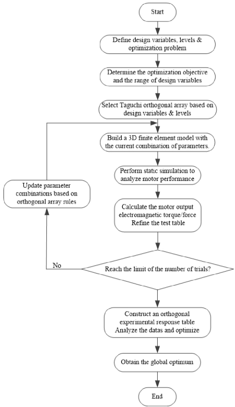
Figure 2: Flow chart of parameter optimization design based on the Taguchi method.
A. Determine the optimization objective and the range of design variables
For the linear rotary SRM designed in this paper, whether it is used as electric or power generation, it is required that the motor torque/power density should be as high as possible, outputting higher electromagnetic torque in rotary motion and higher electromagnetic thrust in linear motion. Considering that the operation principles of the two motions are the same, this paper takes rotary motion as an example to establish a mathematical model of the electromagnetic and mechanical relationships in SRMs. The electromagnetic torque of the motor can be obtained by using its magnetic co-energy for the partial derivation of the motor at any running point x, and the equation is as follows [14]:
| (5) |
Tx is the instantaneous electromagnetic torque of the motor, is the relative position of the motorized motor, i is the winding current and W is the winding magnetic co-energy. The winding magnetic co-energy is the result of integrating the winding magnetic chain over the current:
| (6) |
is the motor winding magnetic chain.
Equation (6) is integrated and averaged over one operating cycle. Based on the assumption of symmetry of the windings of each phase, the average SRM output torque is obtained as:
| (7) |
m is the number of phases of the SRM, Nr is the number of rotor poles.
After the initial dimensioning in Table 1, geometrical optimization of the structural parameters of the proposed motor is required in order to have a higher output torque. Therefore, a sensitivity analysis is carried out in this section to obtain the optimum parameters of the proposed MLRSRM. These parameters help to produce maximum electromagnetic torque/thrust. Based on the design experience and the structural characteristics of the MLRSRM, the sensitivity analysis is carried out for the four structural parameters, namely, stator pole arc , rotor pole arc , rotor module radial depth h1, and rotor module edge width h2, in turn, as shown in Fig. 3.
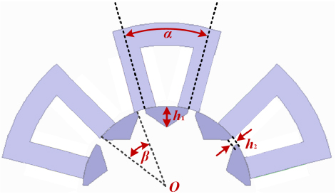
Figure 3: Stator-rotor construction parameters of MLRSRM.
In this paper, a multi-objective optimization of the torque performance of the MLRSRM is carried out, which requires that the output/electromagnetic torque of the motor is as high as possible in both rotary and linear motions. The optimization objectives are chosen as the following two torque indicators: average electromagnetic torque Tavg and average electromagnetic thrust Favg . The stator pole arc , rotor pole arc , rotor module radial depth h1 and rotor module edge width h2 in the previous section are taken as the design variables, and an orthogonal test matrix is established by selecting the appropriate test level values in the annex of the original parameters of the motor. The design variables and their level values are shown in Table 2.
Based on the static torque of the motor at different angles obtained by the FEM, the static average torque of the motor can be obtained by (8):
| (8) |
Ti is the static torque value of the motor at a specific angle and n is the number of sampling points in the finite element calculation. Calculation of the static average thrust is obtained in the same way.
Table 2: Different level values for each design variable
| Design Variable | Level 1 | Level 2 | Level 3 | Level 4 |
| ∘ | 26 | 27 | 28 | 29 |
| ∘ | 27 | 28 | 29 | 30 |
| h1mm | 14 | 16 | 18 | 20 |
| h2mm | 1 | 3 | 5 | 7 |
B. Orthogonal test design
Based on the four design variables (each with four levels) selected in Table 2, an L16(44) orthogonal array was constructed following Taguchi’s experimental design methodology. Compared with the full factorial design, this approach requires only 16 experimental trials to comprehensively evaluate parameter effects, enabling simultaneous optimization of both torque and thrust objectives while dramatically reducing computational load.
Using the time-step FEM, the MLRSRM with 16 different parameter combinations is modeled separately as a three-dimensional finite element in the electromagnetic field finite element simulation software. Based on the winding excitation of the motor, the motor boundary conditions are set and the model is reasonably dissected. Static simulation under rated operating conditions is performed for each finite element model. The average torque and average thrust corresponding to different parameter combinations of the MLRSRM are obtained. The 4-factor and 4-level Taguchi orthogonal test table and test results are shown in Table 3.
Table 3: Taguchi orthogonal test table and MLRSRM test results
| Test Number | Test Matrix | Test Result | ||||
| ∘ | ∘ | h1mm | h2mm | TavgNm | FavgNm | |
| 1 | 26 | 27 | 14 | 1 | 41.3 | 134.0 |
| 2 | 26 | 28 | 16 | 3 | 42.1 | 141.5 |
| 3 | 26 | 29 | 18 | 5 | 42.3 | 149.5 |
| 4 | 26 | 30 | 20 | 7 | 41.1 | 153.8 |
| 5 | 27 | 27 | 16 | 5 | 41.7 | 140.5 |
| 6 | 27 | 28 | 14 | 7 | 40.3 | 146.7 |
| 7 | 27 | 29 | 20 | 1 | 44.7 | 141.0 |
| 8 | 27 | 30 | 18 | 3 | 43.2 | 149.7 |
| 9 | 28 | 27 | 18 | 7 | 41.6 | 141.0 |
| 10 | 28 | 28 | 20 | 5 | 43.4 | 147.2 |
| 11 | 28 | 29 | 14 | 3 | 41.8 | 147.5 |
| 12 | 28 | 30 | 16 | 1 | 43.1 | 141.0 |
| 13 | 29 | 27 | 20 | 3 | 43.0 | 138.0 |
| 14 | 29 | 28 | 18 | 1 | 43.1 | 137.1 |
| 15 | 29 | 29 | 16 | 7 | 40.2 | 148.6 |
| 16 | 29 | 30 | 14 | 5 | 39.5 | 151.5 |
In order to analyze the influence of the parameter changes of the motor design variables on the optimization objectives and the proportion, a statistical analysis of the experimental data is carried out, according to the orthogonal test table established above and the FEA results in Table 3, to obtain the proportion of the influence of all design variables on each optimization objective. Analysis of mean and variance are carried out first.
The average value of the finite element simulation results of each optimization objective can be calculated by equation (8), and the results are shown in Table 4:
| (9) |
m is the average value of the experiment, n is the number of experiments and Si is the optimization objective value for the ith time.
Table 4: Mean value of the optimization objective
| TavgNm | FavgNm | |
| m | 42.0 | 144.3 |
The average value of the simulation results for each optimization objective under different optimization factors taking different level values can be calculated, taking the average electromagnetic torque Tavg of under level 1 as an example, and the equation obtained is:
| (10) |
In addition, in order to facilitate the analysis, a multi-objective optimization function is introduced to measure the importance of each variable, and the weight factor is used to evaluate the comprehensive consideration of each factor on the optimization objective. The multi-objective function equation is:
| (11) |
1 and 2 are the weight factors of average torque and average thrust, respectively. In this paper, the values of 1 and 2 are both 0.5.
Referring to the above calculations, the average values of the average electromagnetic torque Tavg and the average electromagnetic thrust Favg can be obtained for each design variable taken at different levels. The results are shown in Table 5.
Table 5: Optimization value of structural parameters
| Design Variable | Level | Tavg Nm | Favg Nm | Fobj |
| ∘ | 1 | 41.7 | 144.7 | 0.969 |
| 2 | 42.5 | 144.5. | 0.978 | |
| 3 | 42.5 | 144.2 | 0.977 | |
| 4 | 41.4 | 143.8 | 0.963 | |
| ∘ | 1 | 41.9 | 138.4 | 0.951 |
| 2 | 42.2 | 143.1 | 0.970 | |
| 3 | 42.2 | 146.7 | 0.982 | |
| 4 | 41.7 | 149.0 | 0.984 | |
| h1mm | 1 | 40.7 | 144.9 | 0.958 |
| 2 | 41.8 | 142.9 | 0.964 | |
| 3 | 42.6 | 144.3 | 0.978 | |
| 4 | 43.0 | 145.0 | 0.985 | |
| h2 mm | 1 | 43.1 | 138.3 | 0.964 |
| 2 | 42.5 | 144.2 | 0.977 | |
| 3 | 41.7 | 147.2 | 0.978 | |
| 4 | 40.8 | 147.6 | 0.969 |
According to the average value of each optimization objective in Table 4 and the average value of each design variable under different levels of motor performance index in Table 5, the variance (SS) of the optimized design variable under each motor performance index and its weight of influence on the performance of each motor can be calculated by (12):
| (12) |
X is design variable, S is the optimization objective, mX(Si) is the average value of an optimization objective at level i, and m(S) is the average value of the optimization objective. The obtained calculation results are shown in Table 6.
Table 6: Effect of each design variable on the performance index of different motors
| Design Variable | TavgNm | FavgNm | ||
| SS | Percentage | SS | Percentage | |
| ∘ | 0.22 | 12.33% | 0.1 | 0.33% |
| ∘ | 0.05 | 2.67% | 16.0 | 52.29% |
| h1mm | 0.79 | 44.57% | 0.7 | 2.29% |
| h2mm | 0.72 | 40.43% | 13.8 | 45.10% |
| Total | 1.78 | 100% | 30.6 | 100% |
From Table 6, it can be seen that the rotor module radial depth h1 and rotor module edge width h2 have a greater effect on the average electromagnetic torque Tavg . The rotor pole arc and rotor module edge width h2 have a greater effect on the average electromagnetic thrust Favg . Therefore, level 4 is best selected for h1 and . Since the effect of stator pole arc on the average electromagnetic thrust Favg is very small, is best selected at level 2. For the rotor module edge width h2, considering the large Tavg and Favg at the same time, either level 2 or 3 is suitable. In order to verify the above analysis, the experimental results of the simulation combination are quantified by the objective function Fobj. The size of the value directly reflects the influence of the corresponding parameter level on the objective function. Larger values indicate stronger parameter sensitivity. Combined with the results of Fobj calculation in Table 5, the optimal parameter level value combination for multi-objective optimization is finally determined to be (2) (4) h1 (4) h2 (3), at which time the objective function results in the maximum with the optimal design effect. The calculation results of the objective function Fobj are consistent with the above analysis.
C. Comparison of finite element simulation
The parameter values and performance indexes before and after optimization are shown in Table 7, and finite element simulation is performed on the data in Table 7. The simulation results are shown in Fig. 4. Figure 4 shows the waveforms of static electromagnetic torque and static electromagnetic thrust before and after optimization. It can be seen that after the multi-objective optimization based on the Taguchi method, the electromagnetic torque and electromagnetic thrust of the MLRSRM increase significantly, compared with the average electromagnetic torque of 40.2 Nm and the average electromagnetic thrust of 140.2 Nm before optimization, the average electromagnetic torque and the average electromagnetic thrust of the optimized MLRSRM are 43.5 Nm and 148.6 Nm, which are increased by 8.2% and 6.0%, respectively.
Table 7: Comparison of results before and after optimization
| ∘ | ∘ | h1 mm | h2 mm | Tavg Nm | FavgNm | |
| Before Optimization | 30 | 28 | 22 | 3 | 40.2 | 140.2 |
| After Optimization | 27 | 30 | 20 | 4 | 43.5 | 148.6 |
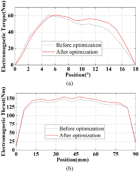
Figure 4: Comparison of static torque and static thrust before and after optimization: (a) rotary motion and (b) linear motion.
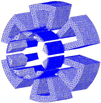
Figure 5: Mesh division diagram of the MLRSRM.
A three-dimensional static model of the motor was constructed in FEA software, and the simulation accuracy was improved by manual mesh refinement. Taking a stator ferromagnetic ring cell as an example, the mesh profile is shown in Fig. 5. Compared with the inner region of the stator-rotor core, the surface of the core close to the air gap is used with a more precise mesh dissection. Specifically, the optimization process implemented by the proposed method consumes less than one day, which is far shorter than the tens of days required by the approach that combines intelligent algorithms with FEA methods. All these iterative operations are carried out on a workstation equipped with Intel Core i7-13650HX and 32-GB memory.
IV. CONCLUSION
In this paper, a three-phase two-degree-of-freedom modular switched reluctance machine (MLRSRM) with a simple structure is presented. A multi-objective optimization design of torque performance based on the Taguchi method is proposed for the structural characteristics and torque characteristics of the proposed MLRSRM. The motor optimization objectives are determined as the static average electromagnetic torque in rotary motion and the static average electromagnetic thrust in linear motion. The key dimensions of the rotor structure selected reasonably are the optimization parameters. The Taguchi experimental method is used to optimize the parameters and obtain the optimized rotor structure parameter combinations and finite element analysis of the motor after optimization. Compared with before optimization, the electromagnetic torque and electromagnetic thrust of the optimized motor are increased by 8.2% and 6.0%, respectively. The effectiveness of Taguchi method in multi-objective optimization of linear rotary SRMs is verified. Future improvements include combining intelligent algorithms, such as genetic algorithms, to improve multi-objective trade-off accuracy and extending experimental validation to actual prototype testing to supplement the reliability of simulation data.
ACKNOWLEDGMENT
This work is supported by the National Natural Science Foundation of China International (regional) cooperation and exchange projects NSFC-RSF under Grant W2412064, the Shenzhen Collaborative Innovation Special Plan International Cooperation Research Project under Grant GJHZ20240218114300002 and the 2023 China-CEEC University Joint Education Program (2023304).
REFERENCES
[1] H. Chen, R. Nie, and X. Li, “A transverse-flux single-phase tubular switched reluctance linear machine with 4 poles,” IEEE Transactions on Applied Superconductivity, vol. 31, no. 8, pp. 1-4, Nov. 2021.
[2] G. Zhang, R. Nie, J. Si, C. Gan, and Y. Hu, “Optimal design of a novel double-stator linear-rotary flux-switching permanent-magnet generator for offshore wind-wave energy conversion,” in 2021 IEEE Energy Conversion Congress and Exposition, Vancouver, BC, Canada, pp. 4300-4305, 2021.
[3] R. Nie, J. Si, P. Wang, Z. Li, J. Liang, and C. Gan, “Optimization design of a novel permanent magnet linear-rotary generator for offshore wind-wave combined energy conversion based on multi-attribute decision making,” IEEE Transactions on Energy Conversion, pp. 1-17, Feb. 2024.
[4] W. Ding, H. Fu, and Y. Hu, “Characteristics assessment and comparative study of a segmented-stator permanent-magnet hybrid-excitation SRM drive with high-torque capability,” IEEE Transactions on Power Electronics, vol. 33, no. 1, pp. 482-500, Jan. 2018.
[5] R. Nie, J. Si, Y. Jia, P. Wang, S. Xu, J. Liang, and C. Gan, “Comprehensive comparison of mover-PM and stator-PM linear-rotary generators for wind-wave combined energy conversion system,” IEEE Transactions on Industry Applications, pp. 1-14, May 2024.
[6] J. Zhang, J. Liu, and L. Gei, “Multi-objective optimization of switched reluctance motor based on Gaussian process regression model,” in 2024 IEEE 10th International Power Electronics and Motion Control Conference, Chengdu, China, pp. 4020-4025, 2024.
[7] O. Zayed, M. Omar, M. Bakr, M. Narimani, A. Emadi, and B. Bilgin, “Switched reluctance motor design for an EV propulsion application,” in IECON 2021 – 47th Annual Conference of the IEEE Industrial Electronics Society, Toronto, ON, Canada, pp. 1-6, 2021.
[8] Z. Xu, Q. Yu, H. Wang, Y. Zhang, and T. Yi, “Optimal design of hybrid stator pole type bearingless switched reluctance motor with simulated annealing particle swarm optimization algorithm,” in 2022 IEEE 5th International Electrical and Energy Conference, Nanjing, China, pp. 3422-3427, 2022.
[9] Y. Geng, C. Huang, H. Yuan, and Y. Wu, “Optimization of a permanent magnet-assisted switching reluctance motor based on the iterative optimization strategy of NSGA-III,” in 2023 IEEE 6th International Electrical and Energy Conference, Hefei, China, pp. 3733-3738, 2023.
[10] T. Sharifi, V. M. Khales, and M. Mirsalim, “Torque ripple minimization for a switch reluctance motor using the Ant Lion Optimization algorithm,” in 2022 13th Power Electronics, Drive Systems, and Technologies Conference, Tehran, Islamic Republic of Iran, pp. 207-211, 2022.
[11] M. Abdalmagid, M. H. Bakr, and A. Emadi, “A linesearch-based algorithm for topology and generative optimization of switched reluctance machines,” IEEE Transactions on Transportation Electrification, vol. 9, no. 3, pp. 3849-3866, Sep. 2023.
[12] S. E. M. Mohammadi, P. Chen, M. Moallem, B. Fahimi, and M. Kiani, “An alternate rotor geometry for switched reluctance machine with reduced torque ripple,” IEEE Transactions on Energy Conversion, vol. 38, no. 2, pp. 939-947, June 2023.
[13] M. Pourkarimi, U. Demr, and M. C. Akuner, “Neural network approach for E-motor development,” in 2022 8th International Conference on Control, Decision and Information Technologies, Istanbul, Turkey, pp. 1091-1095, 2022.
[14] W. Yan, W. Wang, H. Li, H. Chen, F. Yu, D. Zhao, and H. Yang, “Performance analysis of a novel axial radial flux segmental rotor switched reluctance motor,” IEEE Transactions on Transportation Electrification, vol. 10, no. 1, pp. 1031-1042, Mar. 2024.
[15] S.-I. Kim, J.-Y. Lee, Y.-K. Kim, J.-P. Hong, Y. Hur, and Y.-H. Jung, “Optimization for reduction of torque ripple in interior permanent magnet motor by using the Taguchi method,” IEEE Transactions on Magnetics, vol. 41, no. 5, pp. 1796-1799, May 2005.
[16] X. Jia and G. Lu, “An improved random Taguchi’s method based on swarm intelligence and dynamic reduced rate for electromagnetic optimization,” IEEE Antennas and Wireless Propagation Letters, vol. 18, no. 9, pp. 1878-1881, Sep. 2019.
[17] X. Dong, Z. Q. Zhu, D. Liang, L. Mao, X. Qiu, S. Li, and L. Zheng, “Taguchi-based preprocess strategy for fast evaluating worst case cogging torque due to PM tolerance interactions,” IEEE Transactions on Transportation Electrification, vol. 11, no. 1, pp. 4097-4110, Feb. 2025.
[18] J. Yang, J. Chen, Z. Cai, W. Yan, W. Liu, J. Zhang, J. Qiao, G. Yang, and C. Zhang, “Design and optimization of a novel permanent magnet linear motor with the same number of poles and slots,” IEEE Transactions on Industry Applications, vol. 61, no. 1, pp. 16-24, Jan.-Feb. 2025.
[19] J. Chen, K. Liu, Z.-Q. Zhu, H. Cai, S. Zhou, D. Wei, Y. Chen, and D. Zhang, “Torque improvement of interior permanent magnet synchronous machine by axial-assisted magnets,” IEEE Transactions on Transportation Electrification, vol. 11, no. 1, pp. 3480-3490, Feb. 2025.
[20] S. Jiang, J. Wang, B. Zhou, Y. Zhao, M. Gao, S. Miao, L. Xu, and X. Xu, “Design and electromagnetic–thermal analysis of doubly salient electromagnetic machine for more electric engine based on excitation compensation,” IEEE Transactions on Transportation Electrification, vol. 11, no. 1, pp. 3311-3322, Feb. 2025.
[21] Y. Wang, M. Zhao, Y. Huang, X. Jia, and M. Lu, “Torque performance optimization of a novel hybrid PMSM with eccentric Halbach based on improved Taguchi method,” IEEE Transactions on Instrumentation and Measurement, vol. 73, pp. 1-12, 2024.
[22] M. T. B. Tarek, A. W. Bandarkar, and Y. Sozer, “Design, optimization, and development of an axial flux interior permanent magnet motor with a novel flux barrier,” IEEE Transactions on Industry Applications, vol. 60, no. 4, pp. 6103-6112, July-Aug. 2024.
[23] F. Siddique, S. Shastri, and B. Singh, “Computational investigation of modeling coupled optimization techniques for MCSRM driving EV,” IEEE Transactions on Energy Conversion, vol. 39, no. 3, pp. 1793-1803, Sep. 2024.
[24] F. Liu, X. Wang, and H. Wei, “Electromagnetic performance analysis, prediction, and multiobjective optimization for U-type IPMSM,” IEEE Transactions on Industrial Electronics, vol. 71, no. 9, pp. 10322-10334, Sep. 2024.
BIOGRAPHIES

Hao Chen (SM’08) received the B.S. and Ph.D. degrees from the Department of Automatic Control, Nanjing University of Aeronautics and Astronautics, Nanjing, China, in 1991 and 1996, respectively. In 1998, he became an Associate Professor with the School of Information and Electrical Engineering, China University of Mining and Technology, Xuzhou, where he has been a Professor since 2001. From 2002 to 2003, he was a Visiting Professor at Kyungsung University, Busan, Korea. Since 2008, he is an Adjunct Professor at the University of Western Australia, Perth, Australia. He is the author of one book and has authored more than 190 papers. He is the holder of 14 US Patents, 23 Australian Patents, one Danish Patent, seven Canadian Patents, three South African Patents, 10 Russian Patents, 44 Chinese Invention Patents and six Chinese Utility Model Patents. His current research interests include motor control, linear launcher, electric vehicles, electric traction, servo drives and wind power generator control. Chen was the recipient of both the Prize of Science and Technology of Chinese Youth and the Prize of the Fok Ying Tong Education Foundation for Youth Teachers in both 2004. He was awarded the first prize in the Science and Technology advanced of Province and Ministry once, the second prize in the Science and Technology advanced of Province and Ministry seven times, and the third prize in the Science and Technology advanced of Province and Ministry 14 times. He became the Chinese New Century Hundred-Thousand Ten-Thousand Talents Engineering National Talent in 2007 and won the Government Especial Allowance of People’s Republic of China State Department in 2006.

Cheng Liu received the B.S. degree in electrical engineering and automation from Hubei University of Technology, Wuhan, Hubei, China, in 2020, and the M.S. degree in electrical engineering from Hubei University of Technology, Wuhan, Hubei, in 2023. He is currently pursuing a Ph.D. degree in electrical engineering at China University of Mining and Technology, Xuzhou. His research interests include switched reluctance motor design control, ocean wave power generation, and electric vehicles.

Xing Wang received the B.S. degree from China University of Mining and Technology, Xuzhou Jiangsu, China, in 1996, and M.S. degree from China University of Mining and Technology, Xuzhou Jiangsu, in 1999. In 2007, she became an Associate Professor with China University of Mining and Technology, Xuzhou. She is a holder of four US Patents, nine Australian Patents, two Canadian Patents, four Russian Patents, 12 Chinese Invention Patents, three Chinese Utility Model Patents, and has authored 15 papers.

Shudong Hou founded Nanjing Enchuan New Energy Power System Co. Ltd. In September 2022, he won third prize in the high-level talent entrepreneurship competition in Zaozhuang, Shandong. In 2024, he founded Nexus Intelligent Equipment (Zhejiang) Co. Ltd. and serves as its chairman. He has presided over the research, development, production and sales of motor and controller systems for many years.

Antonino Musolino received his Ph.D. degree in electrical engineering from the University of Pisa, Pisa, Italy, in 1994. He is currently a Full Professor of electrical machines at the University of Pisa. He has co-authored more than 130 papers published in international journals/conferences. He holds three international patents in the field of magnetorheological devices. His current research activities are focused on linear electromagnetic devices, motor drives for electric traction, and the development of analytical and numerical methods in electromagnetics. Musolino was involved in the organization of several international conferences, where he has served as the session chairman and an organizer, and as a member of the editorial board.

Nurkhat Zhakiyev received the bachelor’s degree in physics and computer science in 2005, the master’s degree in applied mathematics from M. Utemisov West Kazakhstan State University, Kazakhstan, in 2007, and the Ph.D. degree in physics from L. N. Gumilyov Eurasian National University (ENU), in 2015. He is currently working at Astana IT University. His research interests include energy system modeling, smart grid and networks, smart city and optimization modeling.
ACES JOURNAL, Vol. 40, No. 9, 800–809
doi: 10.13052/2024.ACES.J.400901
© 2025 River Publishers