Research on Electromagnetic Characteristics for an Outer Rotor Doubly Salient Permanent Magnet Reluctance Generator in Direct-drive VerticalAxis Fans
Zhe Zhou, Yifei Gao, Kuan Zhang, Ge Qi, and Shuai Xu
School of Electrical and Information Engineering
Zhengzhou University, Zhengzhou, Henan, 450001, China
Submitted On: December 2, 2024; Accepted On: March 31, 2025
ABSTRACT
To enhance the operation efficiency of generators in variable wind conditions, this paper proposes an outer rotor doubly salient permanent magnet reluctance generator(ORDS-PMRG). First, the operation principles of ORDS-PMRG are presented. Then, the magnetic modulation effect of the multi-tooth structure on generator air-gap flux density is analyzed. Next, the operation modes of the proposed generator are analyzed and can be flexibly switched by changing the winding connection methods. Meanwhile, the electromagnetic characteristic analysis is developed based on the finite element model. The results indicate that the proposed ORDS-PMRG has more operation modes and higher power density compared to traditional doubly salient permanent magnet reluctance generators.
Index Terms: Electromagnetic characteristic, multi-mode operation, outer rotor, permanent magnet reluctance generator.
I. INTRODUCTION
A. Vertical axis wind turbine
As a clean energy source, wind power has emerged as a key focus area in renewable energy development. In the field of distributed generation, vertical-axis wind turbine (VAWT) has many advantages over horizontal-axis wind turbine (HAWT). Notable advantages include its ability to harness wind energy across full speed ranges, simplified installation procedures, and reduced mechanical complexity [1]. The direct-drive VAWT further reduces the transmission structure. The power generation efficiency and reliability of the system have been further improved [2].
In terms of generators, medium and large direct-drive VAWTs mostly use permanent magnet synchronous generators [3], electrically excited synchronous generators, and switched reluctance generators [4]. There are also some generators with hybrid excitation, such as induction reluctance motor [5] and permanent magnet assisted reluctance synchronous motor [6]. However, these generators are subject to problems such as large volume, high maintenance costs, and large vibrations. It is difficult to apply in small direct drive VAWT.
In terms of fan speed regulation, VAWT still needs to pitch the blades to adjust the speed [7]. If the mechanical devices required for fan speed regulation can be reduced, the reliability and power generation efficiency of the power generation system will be further improved, and the cost will be reduced.
B. Permanent magnet reluctance generator
In recent years, permanent magnet vernier generators (PMVG) have been widely adopted because of their large torque and low speed [8, 9]. It is also widely used in the field of direct-drive wind turbines [10, 11].This structure of the generator brings new inspiration to the doubly salient permanent magnet reluctance generators. The tangentially excited PMVG has the characteristics of high mechanical strength and strong excitation ability, which has received further attention [12]. However, in recent years, scholars have gradually noticed that although its power density is relatively large, there is still room for improvement [13]. Several methods are proposed to improve its power density, such as increasing the magnetic bridge to improve the no-load back EMF. Reference[14] investigated a structural design for enhancing power density in generators. By adding two connecting bridges at the stator ends, this configuration effectively increases power generation by over 15%. Reference[15] proposes an innovative asymmetric cross-section rotor design (featuring 45∘ skewed salient poles) for high-speed surface permanent magnet motors, achieving phase synchronization between reluctance torque and magnetic torque for the first time. The breakthrough enhances torque density by 20%.
However, the previous studies have not considered the matching relationship between the generator and wind speed under direct-drive conditions. It is difficult to achieve optimal matching between rotational speed and wind speed with a single operating mode. This paper aims to develop a multi-mode operating generator capable of switching the motor’s operating mode according to different wind speeds.
C. Multi-mode operation
References [16, 17] mentioned some multi-mode operation strategies to control the generator power by changing the connection mode of the winding. However, scholars focus on the constant voltage control of the generator at different speeds. For wind power generation, this will lead to a decrease in power generation efficiency and wind energy utilization [18]. However, its proposed multi-mode operation principle gives the generator the potential for active speed regulation. However, traditional multi-mode operation motors have all adopted a dual-stator structure. This increases the mechanical complexity of the wind power generation system and elevates the probability of system failures. For VAWTs, however, low maintenance costs are one of their key advantages.
D. Contributions
Based on the above content, this paper designs an outer rotor doubly salient permanent magnet reluctance generator (ORDS-PMRG) with multi-mode capability for small direct-drive VAWT. Specifically, it can be summarized as
-
The dual-stator structure of the traditional multi-mode generator is simplified by combining the multi-tooth structure with the multi-mode operation. Reduce the production cost.
-
Electromagnetic analysis based on finite element is carried out. It is proved that the ORDS-PMRG has higher power density and torque density. And the effectiveness of multi-mode operation demonstrates good engineering value.
In this paper, section IIintroduces the structure and operating principles of generators. Section III analyzes the principles of multi-mode operation. In the section IV, the finite element simulation of ORDS-PMRG is carried out. Section V is the summary of the fullpaper.
II. ORDS-PMRG STRUCTURE AND WORKING PRINCIPLE
A. Structure of ORDS-PMRG
An ORDS-PMG is proposed in this paper, as shown in Fig.1. Compared with the traditional structure, ORDS-PMRG is characterized by its multi-tooth structure which can form multiple sets of windings. It can improve the performance of the generator, which will be described in detail in part C of this section.
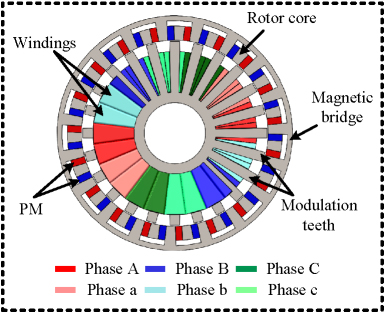
Figure 1: Structure of proposed ORDS-PMRG.
The ORDS-PMRG is designed for VAWT and adopts an outer rotor structure that can be directly connected to the blades. There is a magnetic bridge outside the rotor permanent magnet to connect a magnetic pole of the rotor. This structure has been proven to improve the performance of the tangentially excited PMG. The 24-slot structure improves the diversity of winding connections. It is convenient to realize the multi-mode operation of the generator.
The above-mentioned structural design not only simplifies the mechanical complexity of traditional dual-stator multi-mode generators, but also lays the foundation for subsequent multi-mode operation through the flexibility of the combination of the multi-tooth structure and the windings. The next section will further analyze how this structure achieves the low-speed high-torque operating characteristics, in combination with the principle of magnetic field modulation.
B. Principle of ORDS-PMRG
ORDS-PMRG follows the principle of magnetic field modulation [19]. The rotor magnetic field is modulated by the modulation teeth. The greatest advantage of the PMRG is its ability to achieve low-speed, high-torque operation. Because of the effect of the modulation teeth, the air gap flux density of the generator produces a specific number of harmonics. Its modulation effect can be derived by the following formula:
| (1) |
where denotes the waveform of the magnetic field excited by the excitation source, which is a square wave with zero DC component in ORDS-PMRG. The parameter quantifies the modulation effect induced by the modulation teeth, which is a square wave with a certain DC component. Additionally, is the pole arc coefficient of the rotor, is the number of permanent magnet poles, is the rotation speed of the rotor, is the angle between the rotor and the magnetic pole axis, and is the Fourier coefficient. is the stator tooth arc coefficient, is the number of stator teeth, is the deviation angle of the stator from the center of the slot, and are Fourier coefficients.
Considering only the case where and , by multiplying the two equations in equation (1) and then performing trigonometric transformations, the approximate expression of air gap flux density can be obtained:
| (2) |
The following can be obtained:
| (3) |
The variable represents the number of pole pairs in the generator, which also corresponds to the effective harmonic order of the air gap magnetic field. The next step is to obtain the ratio between the electromagnetic speed and the mechanical speed of the ORDS-PMRG:
| (4) |
where is the angular velocity of the effective harmonic, while refers to the angular velocity of the rotor. Finally, symbolizes the variable gear ratio. From equation (1) to equation (4), the working principle of PMRG with low speed and high torque can be obtained.
Based on the above-mentioned magnetic field modulation principle, the ORDS-PMRG can output high torque at low speeds, meeting the requirements of direct-drive vertical-axis wind turbines. However, a single operating mode is difficult to adapt to the dynamic changes of wind speed, so it is necessary to combine a multi-mode operation strategy.
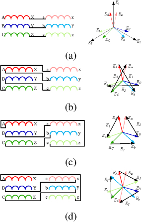
Figure 2: Multi-mode operation schematic: (a) series connection of phase A and phase a, (b) reverse series connection of phase A and phase b, (c) series connection of phase A and phase c, and (d) reverse series connection of phase A and phase c.
III. MULTI-MODE OPERATION
A. ORDS-PMRG with multi-mode operation
For the ORDS-PMRG mentioned in this paper, 24 modulation teeth can form a dual three-phase winding. The combination method is shown in Fig.1. Among them, A B C forms one set of three-phase windings, and a b c forms another set of three-phase windings. Similar to the above, A B C windings and a b c windings are distinguished by color. The two sets of windings are combined to produce different operation modes.
As mentioned above, the previous multi-mode generator needs to be realized by double stators. However, ORDS-PMRG has multiple stator teeth, it can be formed by the combination of different teeth. The method shown in Fig.1 is a double three-phase winding with a 30∘ phase difference.
B. Principles of multi-mode operation
Reference [20] proposes a dual-stator generator that can achieve multi-mode operation. The principle is to adjust the output voltage by connecting the windings on the two misalignment stators. By changing the connection method of the inner and outer windings, a series of EMFs can be generated. As shown in Fig.2, the winding link diagram and EMF vector diagram of the four modes are given. The EMF generated by different operating modes can be approximately obtained by the following formula:
| (5) |
where represents the electrical angle between windings, represents the phase no-load back EMF amplitude. Affected by the winding connection mode and the stator angle.
When the winding link mode is switched, the voltage on the generator load will change. At the same time, the output power of the generator will change. This will affect the speed and torque of the VAWT input to the generator.
At the same time, the multi-mode operation generators often adopt the double stator structure. Because the realization of multi-mode operation requires a certain electrical angle difference between the dual three-phase windings, this makes the manufacture of such generators more difficult and costly. For ORDS-PMRG, a dual three-phase winding with a certain electrical angle difference can be realized without the dual-stator structure.
To verify the effectiveness of ORDS-PMRG and its multi-mode operation, the finite element software is used to simulate it. Key design parameters of the generator are shown in Table 1.
Table 1: Key design parameters of ORDS-PMRG
| Parameters | Value |
| Rated power/kW | 0.75 |
| Rated speed/rpm | 158 |
| PM poles pairs | 19 |
| Teeth number | 24 |
| Poles pairs | 5 |
| Frequency/Hz | 50 |
| Operation modes | 4 |
| Stack thickness/mm | 95 |
| Stator tooth width/mm | 7 |
| Modulation tooth width/mm | 6 |
| Stator yoke thickness/mm | 10 |
| PM length/mm | 14.5 |
| PM width/degree | 3 |
| Magnetic bridge/mm | 5 |
| Stator outer diameter/mm | 90 |
| ORDS-PMRG outer diameter/mm | 230 |
| Winding turns | 60 |
| Length of air gap/mm | 0.5 |
IV. FEA VERIFICATION AND COMPARISON
The finite element simulation of the generator was carried out using Altair Flux software. The 2D finite element models of ORDS-PMRG is established.
A. No-load characteristic
For convenience, the four operating modes of the generator are referred to as M1, M2, M3, and M4 respectively.
Figure 3 shows a comparative analysis of the magnetic density cloud images and magnetic force lines for uneven teeth and even teeth at the same moment. When the magnetic flux in a tooth reaches its maximum, there is a notable difference in the magnetic flux size in another tooth of the same group. The synchronization rate of the magnetic flux between the two teeth in each group is higher for uneven teeth. This results in a larger amplitude of EMF generated by a set of windings under the uneven teeth structure. Consequently, the no-load back EMF of the generator is also increased.
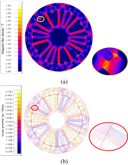
Figure 3: (a) ORDS-PMRG magnetic density cloud and (b) ORDS-PMRG magnetic lines.
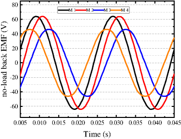
Figure 4: No-load back EMF of ORDS-PMRG.
Figure 4 shows the no-load back EMF of the generator. It can be seen that the amplitude and phase of the no-load back EMF are different under different operating modes. The no-load back electromotive forces (EMF) of ORDS-PMRG are measured as follows: M1 65.93 V, M2 65.91 V, M3 46.44 V, M4 46.42 V.
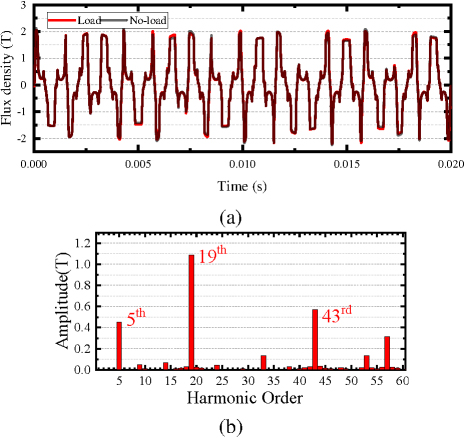
Figure 5: Air gap magnetic density comparison: (a) Air gap magnetic density waveform and (b) Harmonic analysis.
In reality, there is a certain difference between the EMF value obtained by simulation and the value calculated by equation (5). This issue arises closely associated with the actual EMF waveform generated by the ORDS-PMRG. Owing to the influence of permanent magnets, partial magnetic saturation occurs on the stator teeth of the ORDS-PMRG, a phenomenon that is also evident in Fig.3 (a). As a result, the EMF waveform deviates from a purely sinusoidal shape. This phenomenon warrants enhancement in future work.
Figure 5 shows a comparison of air gap magnetic density. An FFT analysis on Fig.5 (a) yields Fig.5 (b). Based on the operating principle of PMVG, the 5th, 19th, and 43th harmonics are the main no-load back EMF sources of the generator.
B. Load comparison
Table 2: Performance characteristics of ORDS-PMRG
| Performance | M1 | M2 | M3 | M4 |
| Average torque (N.m) | 47.0 | 47.0 | 27.6 | 27.6 |
| Torque ripple | 1.55% | 1.63% | 3.6% | 3.3% |
| Rated power (kW) | 0.75 | 0.75 | 0.45 | 0.45 |
| Total loss (W) | 70.5 | 70.6 | 41.0 | 40.9 |
| Efficiency | 90.93% | 90.92% | 91.03% | 91.06% |
Figures 6 and 7 demonstrate the torque and load voltage characteristics across operational modes. While the ORDS-PMRG shows superior torque stability in M1 and M2 with less than 3% ripple variation, this multi-tooth configuration introduces minor trade-offs. The 24-19 stator-rotor poles architecture fundamentally suppresses cumulative pulsations through phase-misaligned dual salient-pole units, as mechanistically validated in [21].
Table 2 shows the performance of ORDS-PMR. Although the absolute value of torque ripple is large, the increase in average torque results is relatively small in its ratio. Furthermore, this structure does not introduce additional losses, maintaining the generator efficiency at a higher level.
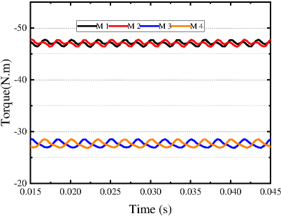
Figure 6: The generator input torque in four operation modes.
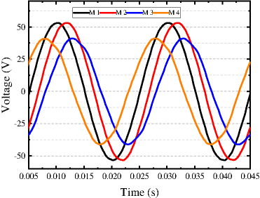
Figure 7: The generator output voltage in four operation modes.
V. CONCLUSION
This paper proposes an ORDS-PMRG for small direct-drive vertical-axis wind turbines, featuring multi-mode operational capability. The design integrates a multi-tooth structure with adaptive operating modes, validated through finite element simulations demonstrating its structural efficacy and operational flexibility. Future directions include:
-
Enhancing power density via modulated tooth topologies and advanced magnetic materials.
-
Implementing model predictive control for real-time mode switching to optimize wind energy harvesting.
These advancements will establish theoretical foundations for next generation switched reluctance and hybrid-excitation motor designs.
ACKNOWLEDGMENT
This project is supported by Natural Science Foundation of Henan Province 252300421316 and he National Natural Science Foundation of China under Grant 52107215.
REFERENCES
[1] S. Roga, S. Bardhan, Y. Kumar, and S. K. Dubey, “Recent technology and challenges of wind energy generation: A review,” Sustainable Energy Technologies and Assessments, vol. 52, no. C, p. 102239, Aug. 2022.
[2] E. Taherian-Fard, R. Sahebi, T. Niknam, A. Izadian, and M. Shasadeghi, “Wind turbine drivetrain technologies,” IEEE Transactions on Industry Applications, vol. 56, no. 2, pp. 1729-1741, Mar. 2020.
[3] M. Zhao, X. Wang, L. Liu, X. Tu, and Q. Yang, “Optimization of PMSM for EV based on vibration and noise suppression,” Applied Computational Electromagnetics Society (ACES) Journal, pp. 64-80, Jan. 2024.
[4] L. Liu, Y. Huang, M. Zhao, and Y. Ruan, “Parametric modeling and optimization of switched reluctance motor for EV,” Applied Computational Electromagnetics Society (ACES) Journal, pp. 948-958, Sep. 2022.
[5] M. Joodi, M. Abbasian, and M. Delshad, “Introducing a 12/10 induction switched reluctance machine (ISRM) for electric powertrains,” Applied Computational Electromagnetics Society (ACES) Journal, pp. 452-460, May 2024.
[6] X. Deng, R. Li, L. Hao, A. Zhang, and J. Zhou, “Design and finite element analysis of a novel permanent magnet assisted reluctance synchronous motor,” Applied Computational Electromagnetics Society (ACES) Journal, vol. 35, no. 9, pp. 1012-1021, Nov. 2020.
[7] D. Ma, “Research on real-time pitch system of H-type vertical axis wind turbine,” master’s thesis, China University of Petroleum (East China),2021.
[8] H. Lin, Y. Zhang, H. Yang, S. Fang, and Y. Huang, “Overview and recent developments of permanent magnet vernier machines,” Proceedings of the CSEE, vol. 36, no. 18, pp. 5021-5034+5127,2016.
[9] X. Li, M. Cheng, G. Zou, and X. Li, “Principle and analysis of a new flux-concentrating field-modulated permanent-magnet wind power generator,” Transactions of China Electrotechnical Society, vol. 29, no. 11, pp. 1-9, 2014.
[10] A. Jafarian-Fini, M. Barghamadi, A. Hajiamiri-Damavandi, and M. Ardebili, “Optimization of an axial flux permanent magnet vernier generator for wind power generation,” in 2023 3rd International Conference on Electrical Machines and Drives (ICEMD), pp. 1-6, Dec. 2023.
[11] P. Sharma and S. Sashidhar, “Permanent magnet vernier generator with surface ferrite magnets for a direct-drive wind generator,” in 2022 International Conference on Electrical Machines (ICEM), pp. 328-333, Sep. 2022.
[12] S. Alshibani, R. Dutta, and V. G. Agelidis, “Optimization of a MW halbach PMSG for wind turbine applications,” in 2016 XXII International Conference on Electrical Machines (ICEM), pp. 1963-1969, Sep. 2016.
[13] J. Mushenya and A. Khan, “Comparative analysis of outer-rotor flux-modulated permanent magnet generator topologies,” in 2020 IEEE Energy Conversion Congress and Exposition (ECCE), Detroit, MI, USA, pp. 1161-1166, 2020.
[14] Y. Zhang, D. Li, P. Yan, X. Ren, R. Qu, and J. Ma, “A high torque density claw-pole permanent-magnets vernier machine,” IEEE Journal of Emerging and Selected Topics in Power Electronics, vol. 10, no. 2, pp. 1756-1765, Apr. 2022.
[15] K. Yamaguchi, T. Yamamoto, N. Omura, and T. Jikumaru, “Torque enhancement of surface permanent magnet motors utilizing reluctance torque for high-speed motors with bonded magnets,” in 2022 International Power Electronics Conference (IPEC-Himeji 2022- ECCE Asia), pp. 678-684, May 2022.
[16] M.-F. Hsieh, F.-S. Hsu, and D. G. Dorrell, “Winding changeover permanent-magnet generators for renewable energy applications,” IEEE Transactions on Magnetics, vol. 48, no. 11, pp. 4168-4171, Nov. 2012.
[17] J. Yu, C. Liu, and H. Zhao, “Design and multi-mode operation of double-stator toroidal-winding PM vernier machine for wind-photovoltaic hybrid generation system,” IEEE Transactions on Magnetics, vol. 55, no. 7, pp. 1-7, 2019.
[18] L. Li, J. Yang, Z. Feng, F. Zou, Q. Bao, Y. Li, and J. Zhao, “Robust control of wind power system with direct-driven PMSG based on effective wind speed estimation,” Smart Power, vol. 51, no. 8, pp. 82-88, 2023.
[19] X. Li, K. T. Chau, and M. Cheng, “Analysis, design and experimental verification of a field-modulated permanent-magnet machine for direct-drive wind turbines,” IET Electric Power Applications, vol. 9, no. 2, pp. 150-159, Feb. 2015.
[20] B. Sun, “Design and optimization of 20kW direct drive vertical axis switched reluctance generator,” master’s thesis, School of Electrical Engineering, University of Science and Technology, 2019.
[21] D. Yan, Z. Chen, Z. Wang, H. Wang, T. Shi, and C. Xia, “The torque ripple reduction in PMAREL machine using time-space harmonics analysis of air-gap flux density,” IEEE Transactions on Industrial Electronics, vol. 69, no. 3, pp. 2390-2401, Mar. 2022.
BIOGRAPHIES

Zhe Zhou received B.E. degree in electrical engineering in 2023 from Henan University of Science and Technology, Henan, China. He is currently pursuing a M.S. degree in electrical engineering at Zhengzhou University. His research interests include permanent magnet generator design.

Yifei Gao received B.S. degree in electrical engineering in 2024 from Henan University of Technology, Henan, China. He is currently pursuing a M.S. degree in electrical engineering at Zhengzhou University. His research interests include fault tolerant control of dual three-phase permanent magnet synchronous motor.

Kuan Zhang received the B.E. degree from China University Mining and Technology, Xuzhou, China, in 2014. She is currently a Ph.D. student at the School of Control Science and Engineering, Zhengzhou University. Her current research interest is multi-motor control.

Ge Qi received the master’s degree in electrical engineering from Harbin Institute of Technology, Harbin, China, in 2004, and the Ph.D. degree in electrical engineering from Huazhong University of Science and Technology, Wuhan, China, in 2010. Currently, she is a lecturer at Zhengzhou University of China. Her main research interests are design and control of special motors.

Shuai Xu (Member, IEEE) received the B.S. degree in electrical engineering and automation and the Ph.D. degree in electrical engineering from the China University of Mining and Technology, Xuzhou, China, in 2014 and 2019. Since 2021, he has been an Associate Professor at Zhengzhou University. His current research interests include motor design and control.
ACES JOURNAL, Vol. 40, No. 9, 893–899
doi: 10.13052/2024.ACES.J.400910
© 2025 River Publishers