Analysis of Magnetic Circuit Characteristics of Axial-radial Hybrid Flux Switched Reluctance Motor
Wenju Yan, Jun Xin, Hongwei Yang, Hao Chen, Ryszard Palka, Marcin Wardach, and Konrad Woronowicz
1School of Electrical Engineering
China University of Mining and Technology, Xuzhou 221116, China
6288@cumt.edu.cn, ts23230161p31ld@cumt.edu.cn, ts22230175p31@cumt.edu.cn, hchen@cumt.edu.cn
2Shenzhen Research Institute
China University of Mining and Technology, Shenzhen 518057, China
3Department of Electrical Machines and Drives
West Pomeranian University of Technology, Sikorskiego 37, 70-313 Szczecin, Poland
ryszard.palka@zut.edu.pl, marcin.wardach@zut.edu.pl, Konrad.Woronowicz@zut.edu.pl
Submitted On: December 3, 2024; Accepted On: May 29, 2025
ABSTRACT
In order to enhance the torque output capability of Switched Reluctance Motors (SRM), this paper proposes two types of axial-radial mixed magnetic flux SRM topological structures with wide-narrow pole and same-tooth pole by combining the respective advantages of axial and radial magnetic fluxes. Two identically shaped axial stator structures are used, distributed on both sides of the rotor, forming an axial magnetic flux path with the central rotor. Simultaneously, on the outer side of the rotor, a radial stator structure is distributed, sharing the rotor to form a radial magnetic flux path. By using equivalent magnetic circuit analysis methods analyzing the flux linkage characteristic in a special position of the two topological structures, the superior torque performance of the axial-radial mixed magnetic flux SRM topology is determined. A prototype is manufactured and experimental verification is conducted.
Index Terms: Axial-radial flux, equivalent magnetic circuit analysis, switched reluctance motor.
I. INTRODUCTION
As a rare-earth-free motor, the Switched Reluctance Motor (SRM) has the following advantages compared to other types of motors: lower cost, made solely from stacked silicon steel sheets; high reliability, with no permanent magnets in the rotor and low environmental requirements; and broad high-efficiency platform, achieving efficient operation over a wide speed range and under different load conditions. When SRM is applied to electric engineering vehicles with large inertia loads, it can fully utilize its high starting torque, low starting current, traction characteristics that allow frequent heavy-load starts, and high structural reliability to meet the various driving conditions of electric engineering vehicles. However, due to its inherent structure, the large torque ripple and low torque density greatly limit the application and promotion of SRM in the field of electric dump trucks for engineering vehicles.
Table 1: Summary of novel topologies for SRM
| Category | Structure | Ref. | Characteristics |
| Segment rotor or stator | Segment rotor | [1, 2] | Short flux path, High output torque |
| Segment stator | [3, 4] | Short flux path, Easy maintenance, High reliability | |
| Double stator | Traditional double stator | [5, 6] | High power and torque density, Low torque ripple |
| Double stator with segment rotor | [7–9] | Low saturation, Flux cancellation |
|
| Double stator with segment stator | [10] | Magnetic field decoupling, Low torque ripple |
|
| Hybrid excitation | PM in the stator slot | [11, 12] | High average torque, Low copper loss, High power density |
| PM at other position | [13] | High output power, Low cogging torque | |
| Axial flux | Axial flux with segment rotor or stator | [14–16] | Short flux path, High torque/power density |
| Axial flux with hybrid excitation | [17] | High power density and efficiency, Demagnetization risk | |
| Axial flux with new materials | [18] | Improve motor torque performance, Cost increase |
In order to enhance the competitiveness of SRM in the field of new energy vehicles, many studies often focus on improving motor topology structures, such as segmented stator or rotor structure, double stator structure, hybrid excitation structure, and axial flux structure. To facilitate a more intuitive understanding of the existing SRM topology structures, Table 1 summarizes the classification and corresponding characteristics of the main SRM topology structures.
Currently, there is limited study on hybrid magnetic flux in SRM. An axial-radial magnetic flux switch reluctance wheel edge drive motor is proposed in [19]. The magnetic circuit characteristics are analyzed by using the axial magnetic conductivity compensation coefficient analytical method, and the inductance and torque characteristics are studied. A new hybrid magnetic circuit switch reluctance generator is introduced in [20], and the feasibility of this method was verified through experimental results from a prototype.
In other motor fields, there is relatively more research on hybrid magnetic flux. An axial-radial magnetic flux high-temperature superconducting permanent magnet synchronous motor is proposed in [21] and, based on the study of the rotor structure and working principle, its mathematical model and magnetic field were analyzed. A type of axial and radial hybrid magnetic flux permanent magnet motor using concentrated windings is proposed in [22]. By combining additional cores with concentrated windings, it has the advantage of high-power density. Reference [23] proposed a new type of hybrid hysteresis motor that combines radial and axial magnetic flux rotors, overcoming the disadvantage of poor output torque and efficiency in traditional hysteresis motors. Reference [24] proposed a novel permanent magnet motor that can switch between axial magnetic flux and radial magnetic flux as needed by using coordinate transformation theory. A brushless hybrid excitation motor with radial-axial direction is proposed in [25], which effectively expands the speed range and improves torque output capability. In order to better reflect the magnetic circuit characteristics of the proposed motors, the authors used a three-dimensional finite element analysis method to analyze the polarity distribution of magnetic flux density under different magnetic potentials.
In order to effectively alleviate the end-winding effect, a hybrid flux motor with end-windings is proposed in [26]. The performance of the motor is analyzed by using analytical calculations and three-dimensional finite element models. By optimizing the tooth size of L-stator and the appropriate tilt of magnet shape, maximum average torque output, low torque ripple and cogging torque are realized
This paper proposes two different stator structures for the Axial-Radial Flux SRM (ARFSRM), namely the Wide-Narrow Poles ARFSRM (WNP-ARFSRM) and the Equal-Width Poles ARFSRM (EWP-ARFSRM). In section II the topological structures of WNP-ARFSRM and EWP-ARFSRM are introduced. Then, by establishing equivalent magnetic circuit models for both motors, the electromagnetic characteristics of the motors are analyzed in section III. Prototypes are manufactured and experimental verification is conducted in section IV. This paper is concluded with section V.
II. STRUCTURE OF ARFSRM
As shown in Fig. 1, the topology of a three-phase 12/10/12 WNP-ARFSRM includes the radial magnetic flux part which consists of rotor core, radial stator core, and radial stator armature winding. Unlike traditional SRM structures, the WNP-ARFSRM adds an axial magnetic flux part, including two axial stator cores, rotor core, and axial stator armature winding. The structure of the left and right axial stators is identical, with wide stator poles alternating along the circumferential direction with narrow stator poles. The armature winding exclusively encircles the wide poles of the axial stator, referred to as excitation poles. Conversely, the narrower poles of the axial stator merely facilitate the magnetic flux path, termed auxiliary poles. To ensure that the axial stator meets the slot fill rate under different radius combinations, the stator tooth pole adopts a parallel slot structure. Similarly, the radial stator also uses an excitation pole and auxiliary pole structure. The axial stator and radial stator share a rotor structure, with the rotor part adopting a block structure. Independent rotor blocks are evenly placed in a non-magnetic rotor sleeve along the circumferential direction. The rotor sleeve is made of epoxy resin material, which has a magnetic isolation function to reduce eddy current losses and reduce overall motor weight.
The axial stator winding connection is shown in Fig. 2 (a). Let us take phase A as an example. On one side of the axial stator, A1 and A2 coils are opposite each other in the horizontal plane and along the circumferential direction are connected in series, and A3 and A4 coils are opposite each other on the other side of the axial stator and connected in series to form the armature winding of the axial stator. On one side of the axial stator, the winding polarity distribution is N-N-N-S-S-S, and on the other side of the axial stator, the winding polarity distribution is S-S-S-N-N-N. Figure 2 (b) shows the radial stator winding connection. If we take phase A as an example, in the radial stator, A5 and A6 coils in relative positions are connected in series to form the armature winding of the radial stator.
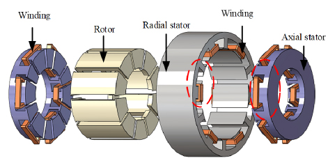
Figure 1: Schematic of the WNP-ARFSRM structure.
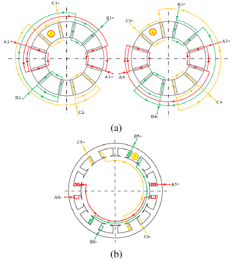
Figure 2: WNP-ARFSRM winding connection diagram: (a) axial stator and (b) radial stator.
Figure 3 presents the topology of a three-phase 12/10/12 EWP-ARFSRM. The axial stator adopts a parallel slot structure. The rotor structure is identical to that of the WNP-ARFSRM. The stator part is similar to the traditional SRM, with coils wound in each slot of both the axial and radial stators. Coils in adjacent slots form the same phase, thereby creating axial and radial magnetic flux paths with the segmented rotor. The two motors proposed in this paper both adopt a centralized winding structure, which has the advantage of minimizing the impact of end effects on the motor, reducing the heat generated during operation and reducing the weight and cost of the motor.
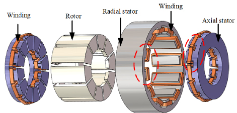
Figure 3: Schematic of the EWP-ARFSRM structure.
The axial stator winding connection method is presented in Fig. 4 (a). Let us take phase A as an example. On one side of the axial stator, the four coils A1, A2, A3, and A4 that are opposite each other in the horizontal plane around the axis are connected in series with each other. They are also connected in series with the coils A5, A6, A7, and A8 that are opposite to them on the other side of the axial stator. If we take phase A as an example again, the radial stator winding connection method is shown in Fig. 4 (b). The coils A9 and A10 are connected in series with coils A11 and A12 that are opposite to them in position.
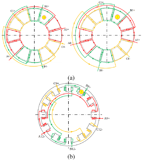
Figure 4: EWP-ARFSRM winding connection diagram (a) axial stator and (b) radial stator.
III. ARFSRM EQUIVALENT MAGNETIC CIRCUIT ANALYSIS
A. Magnetic circuit analysis
Like traditional SRM, the electromagnetic characteristics of ARFSRM also exhibit strong non-linearity and typically operate in a high saturation state. To verify the theoretical concept proposed in this paper for ARFSRM, this section will analyze the equivalent magnetic circuit models of two machines. The equivalent magnetic circuit model of WNP-ARFSRM is shown in Fig. 5, where the mutual inductance and leakage impedance of the winding are ignored. Due to the axial symmetry of the ARFSRM structure, Figures 5 and 7 illustrate only the upper half of the motor for clarity. The lower half shares identical magnetic paths and reluctances, allowing the full magnetic circuit to be represented by doubling the flux values in the depicted half-model.
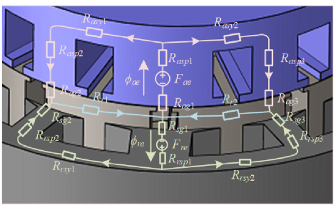
Figure 5: Equivalent magnetic circuit of the WNP-ARFSRM.
In Fig. 5, Fre and Fae represent the magnetomotive force generated by excitation of the radial stator winding and the axial stator winding, respectively. and are the magnetic fluxes produced by the radial stator winding and the axial stator winding, respectively. Rag is the magnetic resistance of the axial magnetic air gap, Rasp is the magnetic resistance of the axial stator pole, Rasy is the magnetic resistance of the axial stator yoke, Rrg is the magnetic resistance of the radial magnetic air gap, Rrsp is the magnetic resistance of the radial stator pole, Rrsy is the magnetic resistance of the radial stator yoke and Rr is the segmented rotor magnetic resistance.
When the rotor is in asymmetric positions, the equivalent network undergoes topological adaptation through the introduction of a leakage reluctance branch Rleak and a cross-coupling reluctance branch Rcross. The leakage branch quantifies the flux leakage caused by partial misalignment between stator and rotor poles, with its value increasing significantly as the rotor angle deviates. The cross-coupling branch captures the magnetic interaction between adjacent phase windings, dynamically updated via FEM-predicted mutual inductancecoefficients.
In order to facilitate formulation of the magnetic circuit equations for WNP-ARFSRM, further simplification is made on the equivalent magnetic circuit, as shown in Fig. 6. Ras1 represents the sum of Rag1 and Rasp1; Ras2 represents the sum of Rag2, Rasp2, and Rasy1; and Rasrepresents the sum of Rag3, Rasp3, and Rasy2. The radial reluctance equivalent is similar to the axial equivalent and will not be further elaborated.
Based on Fig. 6, the basic magnetic circuit equation can be written as:
| (1) |
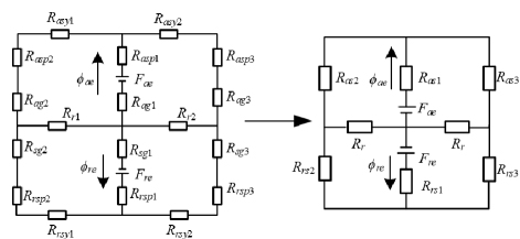
Figure 6: Simplified magnetic circuit of the WNP-ARFSRM.
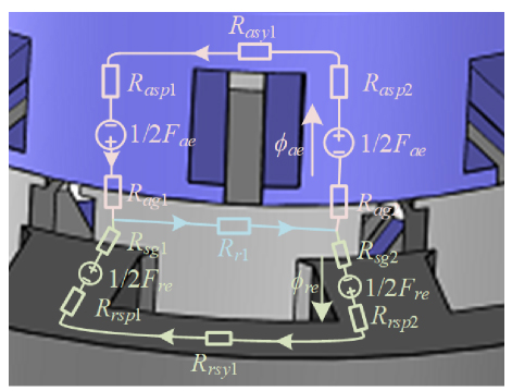
Figure 7: Equivalent magnetic circuit of the EWP-ARFSRM.
The derivation is:
| (4) | |||
| (7) |
The calculation formulas for radial and axial magnetic flux are:
| (8) |
The equivalent magnetic circuit model of EWP-ARFSRM is shown in Fig. 7, while the simplified equivalent magnetic circuit is shown in Fig. 8. Here, Ras represents the sum of Rag1, Rag2, Rasp1, Rasp2, and Rasy1, and Rrs represents the sum of Rsg1, Rsg2, Rrsp1, Rrsp2, and Rrsy1. According to Fig. 8, the basic magnetic circuit equation of EWP-ARFSRM can be written as:
| (9) |
The derivation is:
| (10) |
The calculation formulas for radial and axial magnetic flux are:
The magnetic reluctances in equations (1-7) are functions of rotor position . Their values are dynamically updated in practice based on two approaches: piecewise linearization of the core material’s nonlinear B-H curve for iterative permeability calculations, and interpolation of precomputed finite element data to account for geometric variations in pole overlap. The empirical formulas for the axial airgap reluctance R_ag and radial airgap reluctance R_rg as functions of angular position are:
| (12) |
where Aa represents the effective overlap area between stator and rotor poles (unit: ), s represents the stator pole arc angle (unit: rad), r represents the effective rotor overlap arc angle, Nr represents the number of rotor poles, 0 represents the reference angle at the aligned position, ro, ri represents the outer and inner radii of the airgap region, ga represents the axial airgap length, and 0 represents the permeability of free space.
B. Magnetic circuit solution
Construction of the equivalent magnetic circuit model is based on establishment of the magnetic flux tube. The size of the magnetic resistance can be determined by the magnetic flux tube theorem. The two end faces of the magnetic flux tube are two magnetic equipotential surfaces, and their magnetic potentials are different. Each magnetic field line vertically passes through its cross-section in the magnetic flux tube, as shown in Fig. 9.
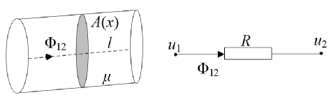
Figure 9: Magnetic flux tube and its equivalent reluctance.
The equivalent magnetic resistance R in Fig. 9 can be calculated as:
| (13) |
Based on the computational method presented in [27], the magnetic flux curves of the motor in both aligned and unaligned positions can be calculated. To reduce errors caused by the magnetic saturation effect of silicon steel sheets, this paper employs the Gauss-Seidel iteration method to solve the nonlinear problems in the equivalent magnetic circuit, with specific procedures referring to [28]. The WNP-ARFSRM and EWP-ARFSRM obtained through iterative calculations are shown in Figs. 10 and 11, respectively. In the proposed ARFSRM design, the axial stator, radial stator, and rotor components all utilize 50DW470 silicon steel sheets as the core material. The magnetization (B-H) curve of this material is shown in Fig. 12.
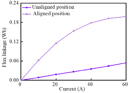
Figure 10: Flux linkage curves by MEC at the unaligned and aligned position of WNP-ARFSRM.
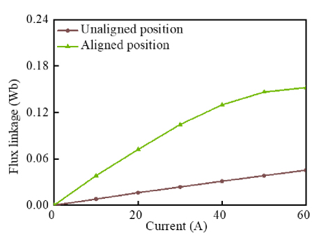
Figure 11: Flux linkage curves by MEC at the unaligned and aligned position of EWP-ARFSRM.
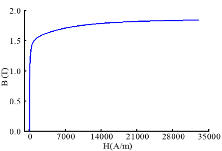
Figure 12: Magnetization (B-H) curve of 50DW470material.
At the unaligned position, the magnetic flux linkage of WNP-ARFSRM is approximately equal to that of EWP-ARFSRM. At the aligned position, with the increase in current, the magnetic flux linkage of WNP-ARFSRM is greater than that of EWP-ARFSRM, which indicates that the maximum-to-minimum inductance ratio of WNP-ARFSRM is larger than that of EWP-ARFSRM and thus has a higher energy conversion ratio.
The electromagnetic torque of the machine is a function of position and phase current i. To solve the electromagnetic torque, a fixed current i is needed. Then, the partial derivative of the magnetic co-energy W’ with respect to the position is solved. The expression is:
The magnetic co-energy is then used to calculate the electromagnetic torque:
| (15) |
According to equations (14) and (15), the average torque of the two machines over half a rotor cycle can be calculated, as shown in Fig. 13. As can be seen from Fig. 13, the average static torque value of WNP-ARFSRM is higher than that of EWP-ARFSRM, indicating that, under the condition of generating the same torque, WNP-ARFSRM requires less current.
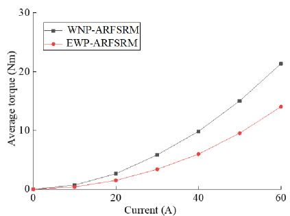
Figure 13: Comparison of average static torque of the two motors.
C. Results analysis
Based on the analysis of the motor magnetic circuit, the following conclusions can be drawn.
-
In the WNP-ARFSRM, due to the adoption of a single-tooth winding structure in both radial and axial directions, narrow poles do not wind the windings but only provide circuits. Therefore, the main magnetic flux is generated by the wide poles with concentrated windings. Both axial and radial directions adopt a wide-narrow pole method, so the equivalent magnetic circuit models for both axial and radial directions are basically consistent, reducing the complexity of deriving formulas.
-
Since the EWP-ARFSRM is powered simultaneously by adjacent coils forming one phase, the magnetic flux path only passes through the two adjacent stator poles. Compared with WNP-ARFSRM, the equivalent magnetic circuit analysis is simpler and more convenient.
-
At the unaligned position of the motor, the magnetic flux generated axially cancels out with the radial direction, thereby improving the maximum to minimum inductance ratio of the motor. At the aligned position of the motor, the magnetic flux generated axially overlaps with the radial direction, thereby increasing the output torque of the motor. Moreover, at the aligned position, the flux linkage of WNP-ARFSRM is greater than that of EWP-ARFSRM.
-
The average static mean torque value of WNP-ARFSRM is higher than that of EWP-ARFSRM.
IV. EXPERIMENT
To verify the correctness of the equivalent magnetic circuit analysis method proposed in this paper, a three-phase 12/10/12 pole WNP-ARFSRM prototype was designed and manufactured. A corresponding motor experimental platform was set up to test the static characteristics of the motor. Figure 13 presents the assembly diagram of the WNP-ARFSRM prototype. Figure 15 shows the actual images of the motor’s radial stator, axial stator, and rotor.
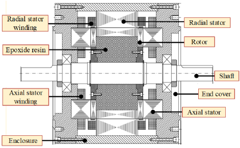
Figure 14: Assembly schematic of the WNP-ARFSRMprototype.
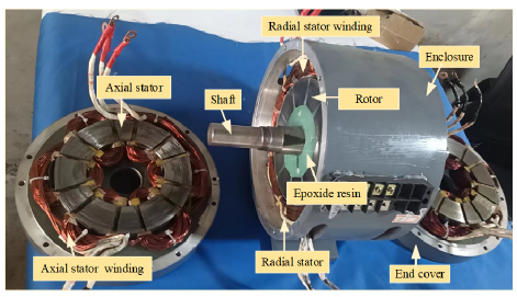
Figure 15: Photo of WNP-ARFSRM prototype.
In order to accurately obtain the magnetic linkage characteristics of the prototype, this paper adopts the indirect method for magnetic linkage measurement. The specific steps are as follows:
-
At the beginning of the experiment, the initial position of the rotor of the calibration motor is found. Taking phase A as an example, the unaligned and aligned positions of the motor are found using an inductance meter and a rotary encoder, and the rotor is clamped with a magnetic powder brake to ensure that the motor is fixed at these two special positions.
-
Apply a 48 V voltage to the phase A winding and detect the changes in phase current and phase voltage through current and voltage sensors. When the winding current reaches 60 A, turn off the switch tube to stop excitation, and record the waveforms of current and voltage changes using an oscilloscope.
-
Using the measured phase voltage and phase current waveforms at unaligned and aligned positions, the characteristics of the phase winding magnetic linkage are derived based on the magnetic linkage calculation formula. The specific calculation formula is as follows:
(16) where ,i, and u represent the phase flux linkage, phase current, and phase voltage of the winding, respectively. R is the resistance value of the phase winding and (0) is the magnetic linkage value at the initial moment, typically taken as (0)0.
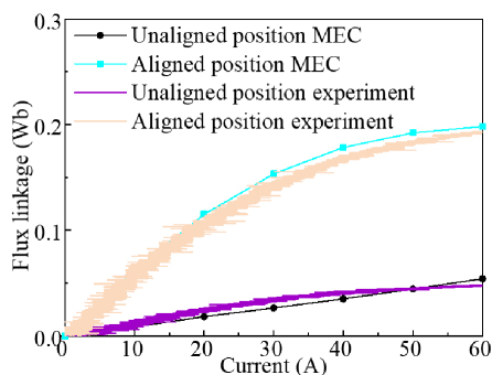
Figure 16: Simulation and measured results of flux linkage.
Figure 16 presents comparison curves of magnetization between experimental measurements and equivalent magnetic circuit calculations for the WNP-ARFSRM prototype. As can be seen from Fig. 16, at the unaligned position, the measured flux linkage values are essentially consistent with the results of equivalent magnetic circuit calculations. At the aligned position, due to motor saturation and manufacturing assembly errors, the flux linkage values obtained from equivalent magnetic circuit calculations are slightly larger than the actual measuredvalues.
V. CONCLUSION
Based on the structural characteristics of axial and radial SRMs, this paper proposes WNP-ARFSRM and EWP-ARFSRM. The electromagnetic characteristics of the two motors are analyzed using the equivalent magnetic circuit method. The following conclusions can be drawn.
-
The radial stator and axial stator share the rotor structure, which is distributed around the rotor block. The rotor block adopts a U-shaped structure and is fixed in a non-magnetic rotor sleeve. Due to the use of segmented rotor structure and concentrated winding, the radial and axial magnetic flux paths of the two motors are shorter, improving the operating efficiency of the motor.
-
By analyzing the magnetic flux paths of WNP-ARFSRM and EWP-ARFSRM at unaligned positions, it was found that the magnetic flux generated by the radial stator cancels out with the magnetic flux produced by the axial stator at the rotor, resulting in a larger maximum to minimum inductance ratio. By analyzing the equivalent magnetic circuit at aligned positions, it was found that the magnetic fluxes generated by the radial and axial stators overlap. The total torque of the motor is the sum of the torques generated by the radial and axial electric excitation.
-
By calculating the magnetic flux of the motor in both aligned and unaligned positions, the average torque of the motor over half a cycle was obtained. The results indicate that the torque output capability of WNP-ARFSRM is stronger than that of EWP-ARFSRM.
ACKNOWLEDGMENT
This work was supported in part by the Xuzhou Science and Technology Innovation Basic Research Project under Grant KC23021, the Guangdong Basic and Applied Basic Research Foundation under Grant 2025A1515011254, China Postdoctoral Foundation Project under Grant 2023M733749, 2022 China-CEEC University Joint Education Program (2022200), 2023 China-CEEC University Joint Education Program (2023304).
REFERENCES
[1] Z. Xu, D.-H. Lee, and J.-W. Ahn, “Design and operation characteristics of a novel switched reluctance motor with a segmental rotor,” IEEE Transactions on Industry Applications, vol. 52, no. 3, pp. 2564-2572, May-June 2016.
[2] X. Sun, K. Diao, G. Lei, Y. Guo, and J. Zhu, “Study on segmented-rotor switched reluctance motors with different rotor pole numbers for BSG system of hybrid electric vehicles,” IEEE Transactions on Vehicular Technology, vol. 68, no. 6, pp. 5537-5547, June 2019.
[3] H. Eskandari and M. Mirsalim, “An improved 9/12 two-phase E-core switched reluctance machine,” IEEE Transactions on Energy Conversion, vol. 28, no. 4, pp. 951-958, Dec. 2013.
[4] L. Szabo and M. Ruba, “Segmental stator switched reluctance machine for safety-critical applications,” IEEE Transactions on Industry Applications, vol. 48, no. 6, pp. 2223-2229, Nov.-Dec. 2012.
[5] M. Asgar and E. Afjei, “Radial force reduction in a new flat-type double-stator switched reluctance motor,” IEEE Transactions on Energy Conversion, vol. 31, no. 1, pp. 141-149, Mar. 2016.
[6] C. H. T. Lee, K. T. Chau, C. Liu, T. W. Ching, and F. Li, “Mechanical offset for torque ripple reduction for magnetless double-stator doubly salient machine,” IEEE Transactions on Magnetics, vol. 50, no. 11, pp. 1-4, Nov. 2014.
[7] Q. Sun, J. Wu, C. Gan, C. Shi, and J. Guo, “DSSRM design with multiple pole arcs optimization for high torque and low torque ripple applications,” IEEE Access, vol. 6, pp. 27166-27175, 2018.
[8] N. Arbab, W. Wang, C. Lin, J. Hearron, and B. Fahimi, “Thermal modeling and analysis of a double-stator switched reluctance motor,” IEEE Transactions on Energy Conversion, vol. 30, no. 3, pp. 1209-1217, Sep. 2015.
[9] L. Maharjan, E. Bostanci, S. Wang, E. Cosoroaba, W. Cai, and F. Yi, “Comprehensive report on design and development of a 100-kW DSSRM,” IEEE Transactions on Transportation Electrification, vol. 4, no. 4, pp. 835-856, Dec. 2018.
[10] W. Yan, H. Chen, S. Liao, Y. Liu, and H. Cheng, “Design of a low-ripple double-modular-stator switched reluctance machine for electric vehicle applications,” IEEE Transactions on Transportation Electrification, vol. 7, no. 3, pp. 1349-1358, Sep. 2021.
[11] W. Ding, H. Bian, K. Song, Y. Li, and K. Li, “Enhancement of a 12/4 hybrid-excitation switched reluctance machine with both segmented-stator and -rotor,” IEEE Transactions on Industrial Electronics, vol. 68, no. 10, pp. 9229-9241, Oct. 2021.
[12] S. Ullah, S. P. McDonald, R. Martin, M. Benarous, and G. J. Atkinson, “A permanent magnet assist, segmented rotor, switched reluctance drive for fault tolerant aerospace applications,” IEEE Transactions on Industry Applications, vol. 55, no. 1, pp. 298-305, Jan.-Feb. 2019.
[13] E. F. Farahani, M. A. J. Kondelaji, and M. Mirsalim, “An innovative hybrid-excited multi-tooth switched reluctance motor for torque enhancement,” IEEE Transactions on Industrial Electronics, vol. 68, no. 2, pp. 982-992, Feb. 2021.
[14] A. Labak and N. C. Kar, “Designing and prototyping a novel five-phase pancake-shaped axial-flux SRM for electric vehicle application through dynamic FEA incorporating flux-tube modeling,” IEEE Transactions on Industry Applications, vol. 49, no. 3, pp. 1276-1288, May-June 2013.
[15] V. S. De Castro Teixeira, T. A. D. S. Barros, A. B. Moreira, and E. R. Filho, “Methodology for the electromagnetic design of the axial-flux C-core switched reluctance generator,” IEEE Access, vol. 6, pp. 65463-65473, 2018.
[16] F. Yu, H. Chen, W. Yan, V. F. Pires, J. F. A. Martins, and P. Rafajdus, “Design and multiobjective optimization of a double-stator axial flux SRM with full-pitch winding configuration,” IEEE Transactions on Transportation Electrification, vol. 8, no. 4, pp. 4348-4364, Dec. 2022.
[17] J.-H. Oh, J.-H. Lee, S.-I. Kang, K.-S. Shin, and B.-I. Kwon, “Analysis of a novel transverse flux type permanent magnet reluctance generator,” IEEE Transactions on Magnetics, vol. 50, no. 2, pp. 809-812, Feb. 2014.
[18] J. Ma, J. Li, H. Fang, Z. Li, Z. Liang, and Z. Fu, “Optimal design of an axial-flux switched reluctance motor with grain-oriented electrical steel,” IEEE Transactions on Industry Applications, vol. 53, no. 6, pp. 5327-5337, Nov.-Dec. 2017.
[19] C. Yang, H. Cao, and S. Xing, “Analytical calculation of magnetic circuit at key positions of axial-radial flux switched reluctance rim driven motor,” in 24th International Conference on Electrical Machines and Systems (ICEMS), Gyeongju, Republic of Korea, pp. 2573-2578, 2021.
[20] X. D. Xue, K. W. E. Cheng, Y. J. Bao, P. L. Leung, and N. Cheung, “Switched reluctance generators with hybrid magnetic paths for wind power generation,” IEEE Transactions on Magnetics, vol. 48, no. 11, pp. 3863-3866, Nov. 2012.
[21] H. Qiu, S. Zhang, W. Li, and C. Yang, “Improvement of ferromagnetic bridge structure of axial–radial flux type permanent magnet synchronous machine,” IEEE Transactions on Industry Applications, vol. 56, no. 4, pp. 3498-3505, July-Aug. 2020.
[22] J. M. Seo, J. Ro, S.-H. Rhyu, I.-S. Jung, and H.-K. Jung, “Novel hybrid radial and axial flux permanent-magnet machine using integrated windings for high-power density,” IEEE Transactions on Magnetics, vol. 51, no. 3, pp. 1-4, Mar. 2015.
[23] R. Nasiri-Zarandi, M. Mirsalim, and A. Tenconi, “A novel hybrid hysteresis motor with combined radial and axial flux rotors,” IEEE Transactions on Industrial Electronics, vol. 63, no. 3, pp. 1684-1693, Mar. 2016.
[24] B. Guo, F. Peng, Z. D. Khedda, F. Dubas, and Y. Huang, “Equivalent transformation between axial- and radial-flux permanent-magnet machines,” IEEE Transactions on Transportation Electrification, vol. 9, no. 2, pp. 3085-3094, June 2023.
[25] X. Wang, Y. Fan, Q. Chen, and Z. Wu, “Magnetic circuit feature investigation of a radial–axial brushless hybrid excitation machine for electric vehicles,” IEEE Transactions on Transportation Electrification, vol. 9, no. 1, pp. 382-393, Mar. 2023.
[26] B. Shi, X. Huang, J. Li, H. Zhang, H. Zhao, and X. Zhang, “Novel end-winding hybrid flux machine,” IEEE Access, vol. 11, pp. 133781-133791, 2023.
[27] H. Chen and W. Yan, “Flux characteristics analysis of a double-sided switched reluctance linear machine under the asymmetric air gap,” IEEE Transactions on Industrial Electronics, vol. 65, no. 12, pp. 9843-9852, Dec. 2018.
[28] H. Chen, X. Liu, and W. Yan, “Three-dimensional magnetic equivalent circuit research of double-sided switched reluctance linear machine,” IEEE Transactions on Applied Superconductivity, vol. 30, no. 4, pp. 1-8, June 2020.
BIOGRAPHIES

Wenju Yan (M’19) received the B.S. degree in Electrical Engineering and Automation from the China University of Mining and Technology, Xuzhou, China, in 2013. He received the Ph.D. degree in electrical engineering from the China University of Mining and Technology, in 2018. Since 2018, he has been with China University of Mining and Technology, where he is currently an associate professor in the School of Electrical Engineering. His current research interests include electric vehicles, electric traction, iron loss analysis and motor design.

Jun Xin received the B.S. degree in Electrical Engineering and Automation from the China University of Mining and Technology, Xuzhou, China, in 2023. He is currently working toward the M.S. degree in electrical engineering from the China University of Mining and Technology. His research interests include integrated drive systems for electric vehicles and double-stator switched reluctance motors.

Hongwei Yang received the B.S. degree in Electrical Engineering and Automation from the School of Mechanical and Electrical Engineering and Automation, Nanhang Jincheng College, Nanjing, China, in 2022. He is currently working toward the M.S. degree in electrical engineering with the China University of Mining and Technology, Xuzhou, China. His research interest includes electric machine design and double-stator switched reluctance motor.

Hao Chen (SM’08) received the B.S. and Ph.D. degrees in Electrical Engineering from the Department of Automatic Control, Nanjing University of Aeronautics and Astronautics, Nanjing, China, in 1991 and 1996, respectively. In 1998, he became an Associate Professor with the School of Information and Electrical Engineering, China University of Mining and Technology, Xuzhou, China, where he has been a professor since 2001. From 2002 to 2003, he was a Visiting Professor at Kyungsung University, Busan, Korea. Since 2008, he has been an Adjunct Professor at the University of Western Australia, Perth, Australia. He is the author of one book and has authored more than 200 papers. His current research interests include motor control, linear launcher, electric vehicles, electric traction, servo drives and wind power generator control. Chen was the recipient of both the Prize of Science and Technology of Chinese Youth and the Prize of the Fok Ying Tong Education Foundation for Youth Teachers in 2004. He became the Chinese New Century Hundred-Thousand-Ten Thousand Talents Engineering National Talent in 2007 and won the Government Especial Allowance of People’s Republic of China State Department in 2006.

Ryszard Palka D.Sc. Ph.D. Eng. is Head of Department of Electrical Machines and Drives, West Pomeranian University of Technology, Szczecin, Poland. In 1987-2005, he was with the Institute of Electrical Machines, Traction and Drives, TU Braunschweig, Germany. Areas of research include electromagnetic field theory, numerical field calculations, optimization of electromagnetic fields, electrical machines and high-temperature superconductivity. He is the author of over 320 refereed journal articles, conference papers, and technical reports, and co-author of four books. He is a member of IEEE, International Compumag Society, Polish Society of Theoretical and Applied Electrical Engineering, International Maglev Board and Committee on Electrical Engineering and Polish Academy ofSciences.

Marcin Wardach D.Sc. Ph.D. Eng. was born in Poland in 1980. He graduated and received the Ph.D. degree from the Electrical Department, Szczecin University of Technology, Szczecin, Poland, in 2006 and 2011, respectively. From 2020 until now, he is an Associate Professor with the Faculty of Electrical Engineering, West Pomeranian University of Technology, Szczecin. His research interests include the design of electrical machines and drives especially unconventional and hybrid excited. He is the author of over 100 scientific papers and post-conference publications. He is a member of the Association of Polish Electrical Engineers and Polish Society of Theoretical and Applied Electrical Engineering.

Konrad Woronowicz received a Ph.D. degree in adaptive linear induction motors (LIM) control and a D.Sc. degree in an area of Wireless Power Transfer (WPT) from the West Pomeranian University of Technology, Szczecin, Poland, in 2001 and 2015, respectively. From 1995 until 2019, he was with Bombardier Transportation, Canada, involved in various transportation and research and development projects and played a key role in commercializing LIM-based mass transit systems in such locations as New York, Beijing, Vancouver, Kuala Lumpur and Seoul. Later, he partook in the development of a high power WPT system for buses and light rail vehicles. He has authored numerous patents in WPT, converter topology, converter controls, and motors. He is currently an Associate Professor with the West Pomeranian University of Technology, Department of Electrical Engineering. His current research interests include electromagnetic design for WPT, development of high-performance linear motors, resonant circuits and power conversion for energy storage.
ACES JOURNAL, Vol. 40, No. 9, 872–882
doi: 10.13052/2024.ACES.J.400908
© 2025 River Publishers