Dynamic Evolutionary Control Strategy for Switched Reluctance Generator DC Microgrid System
Wenju Yan, Yang Wang, Jiangpeng Hu, Hao Chen, Ryszard Palka,
Marcin Wardach, and Konrad Woronowicz
1School of Electrical Engineering
China University of Mining and Technology, Xuzhou 221116, China
6288@cumt.edu.cn, ts23230161p31ld@cumt.edu.cn, ts22230175p31@cumt.edu.cn, hchen@cumt.edu.cn
2Shenzhen Research Institute
China University of Mining and Technology, Shenzhen 518057, China
3Department of Electrical Machines and Drives
West Pomeranian University of Technology, Sikorskiego 37, 70-313 Szczecin, Poland
ryszard.palka@zut.edu.pl, marcin.wardach@zut.edu.pl, Konrad.Woronowicz@zut.edu.pl
Submitted On: December 3, 2024; Accepted On: June 11, 2025
ABSTRACT
This paper introduces a double-stator novel switched reluctance machine employed as a wind generator. To stabilize the fluctuating power output of an off-grid wind power storage system and maintain the bus voltage stability of the power generation system, a dynamic evolutionary control strategy utilizing closed-loop bus voltage regulation is proposed. This includes constructing a multi-objective optimization function with four parameters: power generation efficiency, output voltage, torque smoothness coefficient, and power smoothness coefficient. These parameters serve as the basis for mode selection in multi-mode operation. Furthermore, in order to further enhance the system’s power generation efficiency, a real-time optimization method based on efficiency optimization for the commutation angle is designed. The integration of these two methods results in a multi-mode operation method for double-stator switched reluctance generator (DSSRG) based on efficiency optimization control. Simulation and experimental results validate the feasibility and effectiveness of the new DSSRG system and its control methods. This research holds significant importance for the application of DSSRGs in the field of power generation.
Index Terms: Efficiency optimization, Fibonacci search algorithm, mode selection, switched reluctance generator.
I. INTRODUCTION
The overconsumption of fossil energy has led to global warming, and there is an urgent need for clean energy to supplement and replace traditional fossil energy. New energy sources represented by wind power are being developed and utilized on a large scale, and wind power has the advantages of being clean and renewable, relatively low development cost and wide application prospects [1–3]. The switched reluctance generator (SRG) has a simple structure, low cost, no windings on the rotor, made of silicon steel sheet stacked and pressed, does not need permanent magnet efficiency and other characteristics, and can be based on the change of wind speed real-time change in the excitation current for maximum power tracking to improve the utilization of wind energy [4–5]. Compared with synchronous generators, SRG emits direct current (DC), has no output frequency limitation at different wind speeds, and can be used to generate power with variable speed direct drive, which has good research significance and application potential in the field of wind power generation. The SRG is fault tolerant during operation, has good temperature resistance, can still operate stably even under phase loss conditions, and is highly adaptable to harsh environments [6–7].
DC microgrids, as an emerging technology, can easily integrate renewable energy and energy storage devices. In many remote areas abundant in wind energy and other renewable resources, implementing wind-powered DC microgrid systems to achieve electricity self-sufficiency is a cost-effective approach to enhancing local living standards and improving inhabitants’ quality of life [8–9].
The variable and unpredictable nature of wind energy can significantly impact the grid when renewable energy sources are widely utilized. Sudden variations in renewable energy sources can result in voltage fluctuations, negatively affecting the power quality of the grid. Stochastic fluctuations in renewable energy sources are unavoidable. To address the power fluctuations, energy storage devices are used as energy buffers so as to maintain the power balance and overall stability of the wind turbine DC microgrid system [10]. In [11], the authors propose a model predictive control strategy for DC microgrids, where the energy storage system’s state of charge is constrained to operate within a safe range. However, the implementation of model predictive control is discrete as it depends on scattered system models and cost functions. In [12], the energy storage system of electric vehicles uses an adaptive fuzzy logic control (AFLC) method. The energy storage system’s power target value can be calculated by the AFLC method, which helps to keep the overall power balance of the system stable. However, a lot of computing resources are required in the proposed control strategy. In [13], adaptive neural network control technology is used to regulate the current of the energy storage system in electric vehicles. In this method, a variety of datasets are used to train the neural network control and generate an optimal current reference at a given load condition. However, its performance relies on the size of the dataset used to train the artificial neural network and can only ensure superior performance with sufficient computing resources. In [14], the extended droop control method extends traditional resistance-based droop characteristic control by incorporating emulated capacitance droop characteristic control to produce the current reference for the energy storage system. The traditional PI-based double closed-loop control for voltage and current regulation has a wide parameter range for the PI controller, and its performance is highly sensitive to parameter selection [15–17]. When the system’s operating point shifts, the PI parameters often fail to adapt to the new conditions, compromising the stability of the DC microgrid system during sudden changes in wind power generation or load demand [18]. In [19], dynamic evolutionary control has been applied to the reversible converter control of a fuel cell system driving a supercapacitor, achieving better results than those obtained with the traditional PI strategy. In [20], dynamic evolutionary control improves the boost converter’s transient performance and makes the system better. In [21], supercapacitor systems often use PWM control methods to adjust the operation. The PWM’s advantage lies in its ability to achieve an uninterrupted and effortless transition between energy intaking and releasing operating modes. In [22], the dynamic evolution control (DEC) method has been applied to compute the pulse width ratio of a reversible DC/DC converter using prediction components and feed-forward components to turn on/off switching transistors, which has smaller bus voltage fluctuations and better control effects when there is a disturbance in the system, which is superior to the traditional PI control, but there is always some degree of discrepancy between the set value and the data in reality.
From the above control methods, PI controllers are applied to keep the DC link voltage. Incorrect selection of PI controller parameters can compromise the consistency of the DC bus voltage, making it difficult to keep the overall system stable. Under all circumstances, the DC bus voltage must remain within the defined range to enable the DC microgrid system connecting with the AC grid [23]. A method to obtain the phase current equation used to determine the optimal control variables is proposed in [24]. A novel two phase double layer switched reluctance generator (DLSRG) under static eccentricity fault is introduced and analyzed. The proposed generator consists of two magnetically independent stator and rotor layers [25].
In order to settle the problems above, a DEC method of a bus voltage based on a PI closed-loop is proposed. In the mentioned control strategy, the conventional PI closed-loop control is combined with a dynamic evolutionary control, where the bus voltage is closed-looped by the PI to get a part of the target current, and the bus voltage is controlled by the dynamic evolutionary method. This is a novel method of dealing with the problem that the parameters of the PI controller are difficult to select correctly under different working conditions and that there is a deviation between the actual voltage and the given value of the busbar in the dynamic evolutionary control method.
This paper is organized as follows. The system framework is shown in section II. Section III covers the design of both system and controller parameters. Section IV provides detailed simulation results, while section V presents the experimental results and analysis. Finally, conclusions are drawn in section VI.
II. NOVEL DC MICROGRID SYSTEM FRAMEWORK FOR WIND TURBINES
The overall framework presented in this paper is illustrated in Fig. 1. The generator adopts a 16/18/16 type double-stator switched reluctance generator (DSSRG), which has the windings of the inner stator U-type stator module connected in series with the radially symmetrical position windings to form the four phases of A, B, C and D, respectively. The windings of the outer stator U-type stator module are also connected in series with the radially symmetrical position windings to form four phases of E, F, G and H.
A, B, C and D are opposite to E, F, G and H, respectively. The generator rotor is an inner and outer double-sided convex pole structure, and the inner and outer adjacent rotor convex poles are staggered by 7.5 mechanical angles between their central axes. Different from the winding pole distribution form of DSSRG in the traditional sense, the magnetic field polarity distribution of the inner stator winding of this DSSRG follows the pattern S-N-N-S-S-S-N-S-S-N-S-S-N-S, while the polarity distribution of the outer stator winding is arranged as N-S-S-S-N-S-S-S-S-N-S-S-S-S-N. This configuration enables the DSSRG to simultaneously exhibit the characteristics of both a U-shaped magnetic circuit and a parallel magnetic circuit, which makes the overall working efficiency and power density of the generator higher.
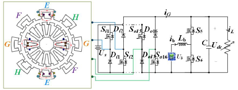
Figure 1: A novel DSSRG power generation system.
The generator is integrated with the DC bus via an asymmetrical half-bridge power converter, and the energy storage device is linked to the bus through a reversible DC-DC converter, with variable loads connected to the bus. According to the operation of the system in reality, the switching signal of the reversible DC-DC converter is controlled to realize the bidirectional flow of energy in the energy storage device. iG, iand idenote the generator, battery, and DC load currents, respectively, and Lb is the filter inductance parameter of the DC-DC converter integrated to the battery. Cdc and Rdc denote the total DC bus capacitance and load resistance, respectively. Ub is the battery’s voltage, Us is the DSSRG excitation supply voltage, and Udc is the DC bus voltage. Si1 and Si2 are the control switches for phase A in the inner stator winding, and Di1 and Di2 are the continuity diodes for phase A in the four-phase winding of the inner stator. Similarly, So9 and So10 are the control switches for phase E in the four-phase winding of the outer stator, Do9 and Do10 are the continuity diodes for phase E in the four-phase winding of the outer stator, and S5 and S6 are the control switches for the reversible DC-DC converter.
III. CONTROL METHODS
A. Control method formulation
The block diagram of the conventional control method employed for stabilizing the DC microgrid bus voltage is presented in Fig. 2.
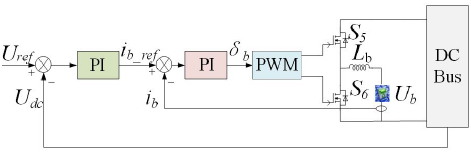
Figure 2: Block diagram of double closed-loop control.
In this method, the deviation term between the DC bus voltage Udc and the bus voltage reference value Uref are sent to the outer-loop PI controller to compute the battery current reference value ib_ref, then the difference between ib_ref and the current sampling value ib is sent to the inner-loop PI controller to get the pulse width ratio of the switching device, and then the switching signals of the power switching transistors of the reversible DC-DC converter are obtained through the PWM modulation to complete the double closed-loop control of the bus voltage system. The control of bus voltage double closed-loop system is completed. Dual closed-loop control requires adjusting the proportional and integral coefficients of the voltage outer loop and current inner loop respectively, and the stability of the DC bus voltage will be directly affected by the target value of the PI regulator parameters. When the operating point of the system is changed, too many PI parameters need to be adjusted which is not conducive to the stability of the system in case of large fluctuations in the generation side or load demand side of the system. In order to settle problems in the above, a DEC strategy of bus voltage based on PI closed-loop (PIDEC) is proposed.
The power balance equation for the entire wind turbine DC microgrid system in the PIDEC is:
| (1) |
where PH is the total power to be dissipated by the energy backup unit, PL is the power requirement and PG is the wind turbine power.
The DC bus voltage reflects the power equilibrium between the generation side, the load side and the energy backup system. In order to respond to DC bus voltage fluctuations and to stabilize the DC bus voltage quickly at a given value of voltage, the battery reference current is:
| (2) |
where iPI is the PI compensation term current value and is the bus voltage error term coefficient. In order to transfer the bus voltage fluctuation to the energy storage device for smoothing, is generally taken as a value of 5 [22].
The energy storage system power PH is separated by the battery voltage Ub to obtain a portion of the transient current reference controlled by a DC-DC converter connected to the battery. In addition, the battery reference current ib_ref includes a bus voltage error term and a PI compensation term, and the battery is controlled using a DEC.
B. Battery current control
Equations (3) and (4) indicate that the battery operates in buck mode and boost mode, respectively. The current dynamics of the reversible DC-DC power converter in one cycle is:
| (3) | ||
| (4) |
where is the switching device’s pulse width ratio in the DC-DC power converter circuit integrated to the battery.
When the external environment changes, battery current control plays a crucial role in quickly achieving DC bus voltage stabilization. Throughout the process, the reversible DC-DC converter operates in a complementary approach, the controller design in the power-boosting mode is analyzed and can be computed from equation (4):
| (5) |
Equation (2) shows that the battery reference current contains the instantaneous current, the PI compensation term current and the bus voltage deviation. For better control of voltage and current, the DEC method is used. Before adopting this method, the dynamic evolution path needs to be selected, and the exponential evolution path selected here is shown in equation (6). The corresponding dynamic evolution process is shown in equation (7) :
| (6) | |||
| (7) |
where denotes the transient characteristics of the system, Ueis the starting value of the system deviation voltage and is the rate at which the deviation voltage is minimized when the system responds. To ensure that the proposed evolutionary path reduces the error voltage to zero quickly, in practice, a linear function of the dynamic characteristics of the system is given as:
| (8) |
where is a direct proportionality factor.
Combining equations (7) and (8), the new dynamic evolution process is obtained as:
| (9) |
Combining equations (4) and (9), we get:
The bidirectional DC/DC circuit switching transistor duty cycle linked to the battery is obtained from the above analysis:
Control of the pulse width ratio of the switching transistor in the above equation consists of four parts. The first is the feed-forward term, which is sensitive to the change of the input voltage and helps to compensate it in time. The second is the voltage deviation ratio term, which can enhance the response speed for minimizing the voltage deviation. The next term is the derivative term of the voltage error, and the last reacts to the change of the inductance current which is also the change of the energy intaking and releasing currents of the energy storage system. In PIDEC, the coefficients of each item change with the change of output voltage, which can make the bus voltage stabilize at the given value more quickly, and the PIDEC requires fewer parameters to be adjusted and simplifies the framework of the controller compared with the traditional double closed-loop control method. The block diagram of this control method is shown in Fig. 3.
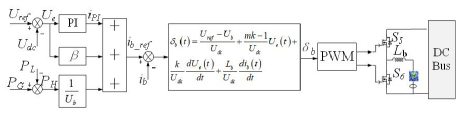
Figure 3: Block diagram of PIDEC control.
IV. SIMULATION ANALYSIS
Under the MATLAB/Simulink simulation environment, the simulation model of the DC microgrid system of double-stator switched reluctance wind turbine is constructed as shown in Fig. 4.
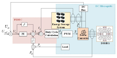
Figure 4: Model of DC microgrid system with DSSRG.
The switch-on and switch-off angles of the fixed switched reluctance generator in the type and the simulation platform parameter settings are provided in Table 1.
Table 1: Simulation platform parameters
| Parameters | Value |
| DC bus voltage (V) | 48 |
| Rated battery voltage (V) | 24 |
| Battery capacity (Ah) | 21 |
| DC bus capacitor (F) | 5e-3 |
| Bus voltage error term gain | 5 |
| Evolutionary coefficient | 31 |
| Proportionality coefficient | 0.03 |
| Switching frequency (Hz) | 20000 |
| Sampling time (s) | |
| Voltage proportionality coefficient | 1.1 |
| Voltage integration coefficient | 80 |
To validate the effectiveness of the PIDEC, the aforementioned simulation platform is utilized to simulate and compare the traditional PI voltage-current double-closed-loop control strategy with the DEC strategy for bus voltage based on the PI closed-loop.
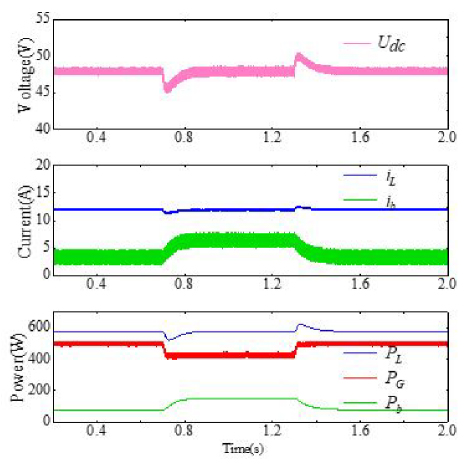
Figure 5: Double closed-loop control strategy.
A. System performance at variable speeds
System simulation is carried out under a certain load. In order to simulate the change of motor speed caused by the change of wind speed during the actual operation of the wind turbine, the initial speed of the motor is set to be 900 r/min, the speed is reduced to 600 r/min in 0.7 s, and the speed is restored to 900 r/min in 1.3 s and, under the above conditions, the PIDEC control strategy and the traditional voltage double-closed-loop control strategy are adopted respectively for simulation. The simulation results are shown in Figs. 5 and 6. The simulation results show that at 0.7 s, the generator speed decreases from 900 r/min to 600 r/min due to the wind speed becoming slower, the generating power decreases and RL is 4, and the load power remains constant. In this case, the power generated is less than the power consumed by the load, and the system power deficit is replenished by the releasing of the energy backup device, and the releasing current of the battery increases. At 1.3 s, the wind speed returns to 900 r/min, the turbine generating power increases, the system power difference decreases, and the battery discharge current becomes smaller. The bus voltage waveforms in Figs. 5 and 6 show that, compared with the traditional double-closed-loop control strategy, the DC bus voltage of the PIDEC has smaller bus voltage fluctuation and shorter bus voltage recovery time at the moment of perturbation, and the energy storage device has a faster current response.
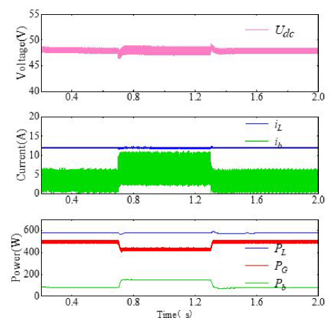
Figure 6: PIDEC control strategy.
B. System performance under variable load scenarios
The motor speed is set to 900 r/min, the generating power is constant, and the load is changed to simulate the change of load power during the actual operation of the system. The simulation results are shown in Figs. 7 and 8. At 0.7 s, the load RL 4 is reduced to RL 3, the load power demand increases, the generation power remains unchanged, the generation is less than the demand for electricity, and the energy releasing current of the energy storage device increases to compensate for the increased load power demand. At 1.3 s, the load reverts to 4, the load power demand is reduced and the battery discharge power is subsequently reduced to meet the overall power balance of the system. The simulation results show that, at the moment of load change, the control method proposed in this paper exhibits superior dynamic characteristics and better system stability compared to the double closed-loop control.
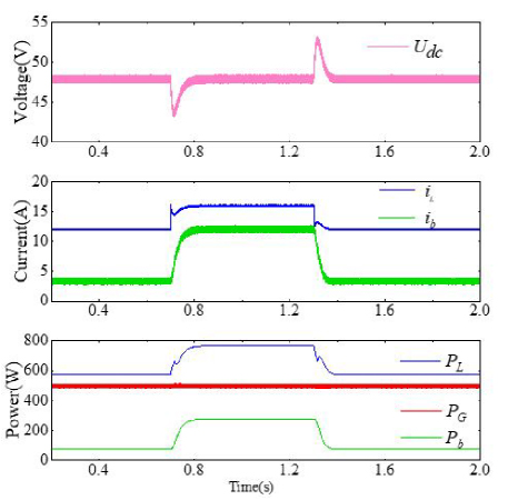
Figure 7: Double closed-loop control strategy.
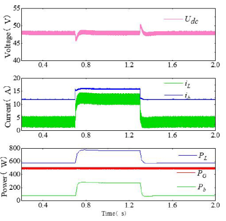
Figure 8: PIDEC control strategy.
C. System performance under variable bus reference voltage scenarios
If we set the bus voltage reference Uref to change from 48 V to 55 V, the motor speed to remain at 900 r/min, and the load RL is kept at 4, we can observe the output voltage shift. Figure 9 shows the simulation results using the conventional voltage double closed-loop control strategy when the dc bus reference voltage is varied. Fig. 10 shows the simulation results using the PIDEC control strategy when the dc bus reference voltage is varied. At 0.6 s, the bus voltage reference value Uref changes from 48 V to 55 V. In this case, the load current iL increases from 12 A to 13.75 A. If the load demand increases and the power deficit of the system increases, the power required to keep the system stable is supplied by the energy storage system, and it is evident from the simulation results that the bus voltage has a much faster response under the PIDEC.
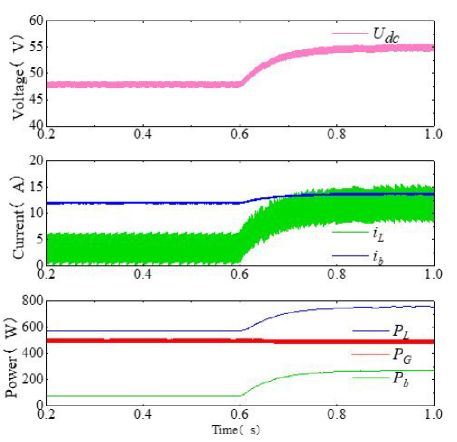
Figure 9: Double closed-loop control strategy.
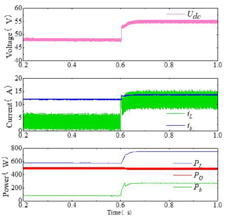
Figure 10: PIDEC control strategy.
V. EXPERIMENTAL VERIFICATION
In order to verify the feasibility of the control method proposed in this paper, an experimental platform was constructed and is presented in Fig. 11. The DSSRG prototype, power converter, bidirectional DC-DC converter, controller, DC excitation source, energy storage device, resistive load, permanent magnet synchronous motor (PMSM), and other parts are included in the experimental platform. The relevant parameters of the double-stator motor are shown in Table 2.
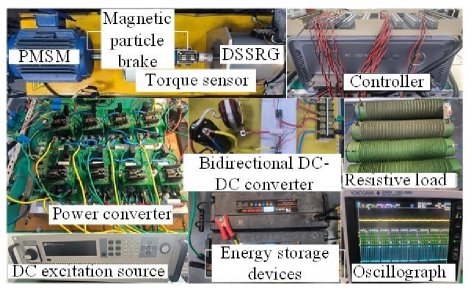
Figure 11: Test platform.
Table 2: Parameters related to DSSRG
| Parameter | Value |
| Poles | 4 |
| Convex pole number | 16/18/16 |
| Rated voltage (V) | 48 |
| Rated power (W) | 1600 |
| Number of turns of outer stator convex pole | 22 |
| Number of turns of inner stator convex pole | 17 |
A. Variable speed experiment
The observational results of the customary PI control method and the PIDEC for the experiment of variable speed are shown in Figs. 12 and 13, respectively.
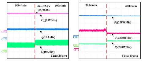
Figure 12: Experimental results of PI control under variable speed: (a) Changes in Udc, iL and ib and (b) changes in PL, PG and Pb.
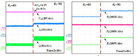
Figure 13: Experimental results of PIDEC control at variable speed: (a) Changes in Udc, iL and ib and (b) changes in PL, PG and Pb.
During the process, the DC resistive load Ris maintained at 4. The motor speed is changed from 900 r/min to 600 r/min, the generating power is changed from 500 W to 440 W, and the load power is kept at about 576 W. The stability of the system is maintained by an energy storage device after a change in generation power. The battery power Pb is increased from 76 W to 136 W to compensate for power instability. From the observational results, it can be seen that the DC bus voltage overshoot of the conventional control method is about 4.5% and the bus voltage recovery time ts is 0.28 s. By using the PIDEC, improved regulation of the DC voltage across the link is achieved. The Mp of the PIDEC is less than 2.3% and the ts is less than 0.08 s.
B. Variable load experiment

Figure 14: Experimental results of PI control under variable load: (a) Changes in Udc, iL and ib and (b) changes in PL, PG and Pb.
In the variable load experiment, the functionality of the customary control method is shown in Fig. 14 and the performance of the PIDEC is shown in Fig. 15. In the experiment, the load RL is decreased from 4 to 3, the load current iL is increased from 12 A to 16 A accordingly, and the motor speed is kept at 900 r/min. In order to keep the DC voltage across the bus constant when the load power is stepped, the power deficit is supplemented by the energy backup device, and the battery power Pb is increased from 76 W to 268 W, with a consequent increase in the discharge current of the battery. From the experimental results, it can be observed that the DC bus voltage overshoot of the customary control method is about 8.7%, and the bus voltage recovery time ts is 0.3 s. The PIDEC has Mp less than 3.2% and ts less than 0.06 s. The control method achieves better DC bus voltage regulation with greater robustness.
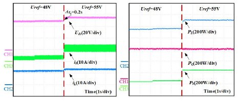
Figure 15: Experimental results of PIDEC control under variable load: (a) Changes in Udc, iL and ib and (b) changes in PL, PG and Pb.
C. Variable DC bus reference voltage experiment
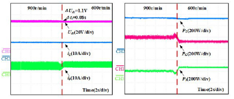
Figure 16: Experimental results of PI control under variable bus reference voltage: (a) Changes in Udc, iL and ib and (b) changes in PL, PG and Pb.
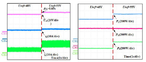
Figure 17: Experimental results of PIDEC control under variable bus reference voltage: (a) Changes in Udc, iL and ib and (b) changes in PL, PG and Pb.
The observed results at a reference change in DC bus voltage are shown in Figs. 16 and 17. The voltage at the output is changed from 48 V to 55 V. At the same time, RL is maintained at 4 and the motor speed is kept at 900 r/min. It is observed that, due to the increase in bus reference voltage, the load power increases. The power required to keep the system stable is provided by the battery and the battery power Pb is increased from 76 W to 256 W to compensate for the system power fluctuation. As the DC bus voltage changes, the load current iL increases accordingly from 12 A to 13.75 A. It can be seen that the bus voltage response time t is 0.2 s for the conventional control strategy, and the PIDEC is more effective at handling step changes in the reference value of the output voltage, with a response time t of 0.05 s from the experimental results. The response time t is 0.05 s for the conventional control strategy.
D. Stability comparison
Based on the above experimental results, Table 3 compares the bus voltage overshoot Mp and the recovery time ts of the PIDEC with the conventional control strategy under different experimental conditions, where Mp is calculated as:
| (12) |
where is the maximum value of the voltage deviation from the bus voltage reference.
Table 3: Comparison of bus voltage stability performance under different control strategies
| Situation | Parameter | Conventional | PIDEC |
| Speed change | Voltage overshoot ( ) | 4.5% | 2.3% |
| Recovery time | 0.28 s | 0.08 s | |
| Load change | Voltage overshoot ( ) | 8.7% | 3.2% |
| Recovery time ( ) | 0.3 s | 0.06 s | |
| Bus voltage change | Response time | 0.2 s | 0.05 s |
VI. CONCLUSION
This paper focuses on the use of a new DSSRG for wind power generation and proposes a new DSSRG standalone DC microgrid system. A dynamic evolutionary control strategy based on a closed-loop bus voltage is proposed for this new DC microgrid system. The control method combines the traditional closed-loop control and DEC, which has an improvement effect on the problem of the PI controller parameters being difficult to be correctly selected under different working conditions in the traditional PI control and the problem of the actual voltage deviating from the given value of the busbar in the DEC method. The proposed method is simulated and experimentally verified under three typical working conditions, and it can be seen that the PIDEC control strategy has a smaller bus voltage overshoot and a shorter bus voltage recovery time, which makes the DC bus voltage remain at a given value and improves the power supply quality and reliability of the wind power microgrid. Due to the phenomenon of increased current ripple of the battery with PIDEC control strategy in the experiment, which will damage the battery life of the battery, a hybrid energy storage system, i.e., a storage system with an energy-based storage original battery and a power-based storage element supercapacitor, will be established in the future to achieve the bus voltage stability and the improvement of the dynamic performance without depletion of the battery’s service life.
ACKNOWLEDGMENT
This work was supported in part by the Xuzhou Science and Technology Innovation Basic Research Project under Grant KC23021, the Guangdong Basic and Applied Basic Research Foundation under Grant 2025A1515011254, China Postdoctoral Foundation Project under Grant 2023M733749, 2022 China-CEEC University Joint Education Program (2022200), 2023 China-CEEC University Joint Education Program (2023304).
REFERENCES
[1] V. Paul, D. Katherine, and B. Sukanta, “Grand challenges: Wind energy research needs for a global energy transition,” Wind Energy Science, vol. 7, no. 6, pp. 2491-2496, 2022.
[2] A. Clifton, S. Barber, and Y. Ding, “Grand challenges in the digitalisation of wind energy,” Wind Energy Science, vol. 8, no. 6, pp. 947-974, 2023.
[3] B. Mostafa, S. Mehdi, M. Saad, S. Alex, and H. Ben, “Small-scale wind turbine control in high-speed wind conditions: A review,” Sustainable Energy Technologies and Assessments, vol. 60, p. 103577, Dec. 2023.
[4] N. Vahidreza, K. Shahriyar, and D. Ali, “Output power maximization and optimal symmetric freewheeling excitation for switched reluctance generators,” IEEE Transactions on Industry Application, vol. 49, no. 3, pp. 1031-1042, 2013.
[5] L. Liu, Y. Huang, M. Zhao, and Y. Ruan, “Parametric modeling and optimization of switched reluctance motor for EV,” Applied Computational Electromagnetics Society (ACES) Journal, vol. 37, no. 9, pp. 948-958, 2022.
[6] C. Da-Woon, B. Sang-In, and C. Yun-Hyun, “A study on the maximum power control method of switched reluctance generator for wind turbine,” IEEE Transactions on Magnetics, vol. 50, no. 1, p. 1, 2013.
[7] J. Mukhopadhyay, S. Choudhuri, and S. Senguota, “ANFIS based speed and current control with torque ripple minimization using hybrid SSD-SFO for switched reluctance motor,” Sustainable Energy Technologies and Assessments, vol. 49, p. 101712, Feb. 2022.
[8] F. Nejabatkhah and Y. Li, “Overview of power management strategies of hybrid AD/DC microgrid,” IEEE Transactions on Power Electronics, vol. 30, no. 12, pp. 7072-7089, 2015.
[9] S. Raul, F. Luis, M. G. Carlos Andres, and J. Francisco, “Dynamic evaluation of two configurations for a hybrid DFIG-based wind turbine integrating battery energy storage system,” Wind Energy, vol. 18, no. 9, pp. 1561-1577, 2015.
[10] C. Wan, W. Qian, C. Zhao, Y. Song, and G. Yang, “Probabilistic forecasting-based sizing and control of hybrid energy storage for wind power smoothing,” IEEE Transactions on Sustainable Energy, vol. 12, no. 4, pp. 1841-1852, 2021.
[11] S. K. Kollimalla, A. Ukil, H. B. Gooi, U. Manandhar, and N. R. Tummuru, ”Optimization of charge/discharge rates of a battery using a two-stage rate-limit control,” IEEE Transactions on Sustainable Energy, vol. 8, no. 2, pp. 516-529, Apr. 2017.
[12] H. Yin, W. Zhou, M. Li, C. Ma, and C. Zhao, “An adaptive fuzzy logic-based energy management strategy on battery/ultracapacitor hybrid electric vehicles,” IEEE Transactions on Transportation Electrification, vol. 2, no. 3, pp. 300-311, 2016.
[13] O. Micah, M. Jorge, and D. Juan, “Ultracapacitor-based auxiliary energy system for an electric vehicle: Implementation and evaluation,” IEEE Transactions on Industrial Electronics, vol. 54, no. 4, pp. 2147-2156, 2007.
[14] Q. Xu, X. Hu, P. Wang, J. Xiao, P. Tu, C. Wen, and M. Lee, “A decentralized dynamic power sharing strategy for hybrid energy storage system in autonomous dc microgrid,” IEEE Transactions on Industrial Electronics, vol. 64, no. 7, pp. 5930-5941, 2017.
[15] S. Bayandy, S. Kanat, and D. Ton Duc, “High order disturbance observer-based PI-PI control system with tracking Anti-Windup technique for improvement of transient performance of PMSM,” IEEE Access, vol. 9, pp. 66323-66334, 2021.
[16] Z. Liu, J. Nie, H. Wei, C. Lei, X. Li, and M. Lv, “Switched PI control-based MRAS for sensorless control of PMSM drives using Fuzzy-Logic-Controller,” IEEE Open Journal of Power Electronics, vol. 3, pp. 368-381, 2022.
[17] S. K. Kollimalla, M. K. Mishra, A. Ukil, and H. B. Gooi, ”DC grid voltage regulation using new HESS control strategy,” IEEE Transactions on Sustainable Energy, vol. 8, no. 2, pp. 772-781, Apr. 2017.
[18] Y. Sun, X. Tang, X. Sun, D. Jia, Z. Cao, J. Pan, and B. Xu, “Model predictive control and improved low-pass filtering strategies based on wind power fluctuation mitigation,” Journal of Modern Power Systems and Clean Energy, vol. 7, no. 3, pp. 512-524, 2019.
[19] S. Ahmad Saudi and Y. Abdul Halim Mohamed, “Implementation of dynamic evolution control of bidirectional DC-DC converter for interfacing ultracapacitor energy storage to fuel-cell system,” IEEE Transactions on Industrial Electronics, vol. 57, no. 10, pp. 3468-3473, 2010.
[20] M. Pratap Ranjan and P. Anup Kumar, “A nonlinear control scheme based on dynamic evolution path theory for improved dynamic performance of boost PFC converter working on nonlinear features,” ISA Transactions, vol. 65, pp. 254-261, 2016.
[21] K. Saichand and V. John, ”PWM block method for control of an ultracapacitor-based bidirectional DC–DC backup system,” IEEE Transactions on Industry Applications, vol. 52, no. 5, pp. 4126-4134, Sep.-Oct. 2016.
[22] M. Ujjal, B. Wang, A. Ukil, and G. Hoay Beng, “Dynamic evolution control-based power sharing method for hybrid energy storage system,” IET Power Electronics, vol. 12, no. 2, pp. 276-283, 2019.
[23] L. Xu and D. Chen, “Control and operation of a DC microgrid with variable generation and energy storage,” IEEE Transactions on Power Delivery, vol. 26, no. 4, pp. 2513-2522, 2011.
[24] P. Thongprasri and S. Kitturatsatcha, “Analysis of control variables to maximize output power for switched reluctance generators in single pulse mode operation,” Applied Computational Electromagnetics Society (ACES) Journal, vol. 31, no. 10, pp. 1208-1220, 2021.
[25] E. Afjei and H. Torkaman, “Finite element analysis of switched reluctance generator under fault condition oriented towards diagnosis of eccentricity fault,” Applied Computational Electromagnetics Society (ACES) Journal, vol. 26, no. 1, pp. 8-16, 2022.
BIOGRAPHIES

Wenju Yan (M’19) received the B.S. degree in Electrical Engineering and Automation from the China University of Mining and Technology, Xuzhou, China, in 2013. He received the Ph.D. degree in electrical engineering from the China University of Mining and Technology, Xuzhou, China, in 2018. Since 2018, he has been with China University of Mining and Technology, where he is currently an associate professor in the School of Electrical Engineering. His current research interests include electric vehicles, electric traction, iron loss analysis, and motor design.

Yang Wang received the B.S. degree in Electrical Engineering and Automation from the Hefei University of Technology, Hefei, China, in 2023. He is currently working toward the M.S. degree in electrical engineering from the China University of Mining and Technology, Xuzhou, China. His research interest includes electric machine control.

Jiangpeng Hu received the B.S. degree in Electrical Engineering and Automation, from Anhui University of Science and Technology, Huainan, Anhui, China, in 2020. He is currently working toward the M.S. degree in electrical engineering from the China University of Mining and Technology, Xuzhou, China. His research interests include new energy wind power and hybrid energy storage technologies.

Hao Chen (SM’08) received the B.S. and Ph.D. degrees in Electrical Engineering from the Department of Automatic Control, Nanjing University of Aeronautics and Astronautics, Nanjing, China, in 1991 and 1996, respectively. In 1998, he became an Associate Professor with the School of Information and Electrical Engineering, China University of Mining and Technology, Xuzhou, China, where he has been a professor since 2001. From 2002 to 2003, he was a Visiting Professor at Kyungsung University, Busan, Korea. Since 2008, he has been an Adjunct Professor at the University of Western Australia, Perth, Australia. He is the author of one book and has authored more than 200 papers. His current research interests include motor control, linear launcher, electric vehicles, electric traction, servo drives, and wind power generator control. Chen was the recipient of both the Prize of Science and Technology of Chinese Youth and the Prize of the Fok Ying Tong Education Foundation for Youth Teachers in both 2004. He became the Chinese New Century National Hundred-Thousand Ten-Thousand Talents Engineering National Talent in 2007 and won the Government Especial Allowance of People’s Republic of China State Department in 2006.

Ryszard Palka D.Sc. Ph.D. Eng. is Head of Department of Electrical Machines and Drives, West Pomeranian University of Technology, Szczecin, Poland. In 1987-2005 he was with the Institute of Electrical Machines, Traction and Drives, TU Braunschweig, Germany. Areas of research include electromagnetic field theory, numerical field calculations, optimization of electromagnetic fields, electrical machines, and high temperature superconductivity. He is the author of about 320 refereed journal articles, conference papers, technical reports, and co-author of four books. He is a member of IEEE, International Compumag Society, Polish Society of Theoretical and Applied Electrical Engineering, International Maglev Board and Committee on Electrical Engineering, Polish Academy of Sciences.

Marcin Wardach D.Sc. Ph.D. Eng. was born in Poland in 1980. He graduated and received the Ph.D. degree from the Electrical Department, Szczecin University of Technology, Szczecin, Poland, in 2006 and 2011, respectively. From 2020 until now, he has been an Associate Professor with the Faculty of Electrical Engineering, West Pomeranian University of Technology, Szczecin. His research interests include the design of electrical machines and drives especially unconventional and hybrid excited. He is the author of over 100 scientific papers and post-conference publications. He is a member of Association of Polish Electrical Engineers and Polish Society of Theoretical and Applied Electrical Engineering.

Konrad Woronowicz received the Ph.D. degree in adaptive linear induction motors (LIM) control and the D.Sc. degree in an area of Wireless Power Transfer from the West Pomeranian University of Technology, Szczecin, Poland, in 2001 and 2015, respectively. From 1995 until 2019, he was with Bombardier Transportation, Canada, involved in various transportation and research and development projects and played a key role in commercializing LIM-based mass transit systems in such locations as New York, Beijing, Vancouver, Kuala Lumpur and Seoul. Later, he partook in the development of a high power WPT (Wireless Power Transfer) system for buses and light rail vehicles. He has authored numerous patents in WPT, converter topology, converter controls, and motors. He is currently an Associate Professor with the West Pomeranian University of Technology, Department of Electrical Engineering. His current research interests include electromagnetic design for WPT, development of high-performance linear motors, resonant circuits and power conversion for energy storage.
ACES JOURNAL, Vol. 40, No. 9, 840–850
doi: 10.13052/2024.ACES.J.400905
© 2025 River Publishers