Design of Vortex Forward-Looking SAR Imaging using OAM Beam Modulation
Gaolong Cheng and Ping Li
College of Optoelectronic Information and Computer Engineering
University of Shanghai for Science and Technology, Shanghai 200093, China
chenggaolong3@gmail.com, liping@smic.edu.cn
Submitted On: December 4, 2024; Accepted On: March 27, 2025
ABSTRACT
Forward-looking synthetic aperture radar (SAR) systems often suffer from low resolution and blurred imaging in the azimuthal direction due to the limited variation in Doppler frequency. To address this issue, this paper proposes a novel forward-looking SAR imaging technique leveraging vortex electromagnetic waves and orbital angular momentum (OAM) modulation. The core innovation lies in introducing a new azimuthal Doppler frequency component by establishing a linear relationship between the OAM mode number and slow-time, significantly enhancing azimuthal resolution. The method employs a transceiver system comprising a uniform circular array for transmission, with a single antenna at the center of the array for reception. Additionally, the traditional Range-Doppler (RD) algorithm is optimized to suppress motion-induced azimuthal Doppler interference and isolate mode-induced Doppler effects. Simulation results demonstrate that the proposed method effectively expands the azimuthal Doppler bandwidth, resolving left-right target ambiguity and substantially improving azimuthal imaging quality in forward-looking SAR systems.
Index Terms: Forward-looking SAR imaging, orbital angular momentum (OAM), two-dimensional imaging.
I. INTRODUCTION
Forward-looking imaging has recently attracted significant attention due to its potential applications in airborne reconnaissance, fire control, missile guidance, and aircraft landing under adverse meteorological conditions. However, forward-looking radar systems face inherent limitations compared to synthetic aperture radar (SAR), particularly in the ability to synthesize a larger virtual antenna. The forward-looking radar targets are located in a sector area in front of the carrier trajectory, where the radar-target angle is small. This results in a limited azimuthal Doppler bandwidth due to the small Doppler frequency variation caused by the radar motion. Consequently, the Doppler frequency of targets in the imaging area is highly correlated with both the target position and angle, leading to increased Doppler complexity and variability. This results in low resolution in the azimuthal direction, with left- and right-side targets producing similar Doppler frequencies, causing blurring in the imaging process [1]. As a result, achieving high azimuthal resolution in forward-looking radar imaging remains challenging.
As described in electrodynamics literature, the electromagnetic(EM) angular momentum can be decomposed into two independent parts, namely, spin angular momentum and OAM. The former is linked with polarization,whereas the latter leads to helical phase front. A beam carrying OAM usually has helical wavefront and a doughnut intensity shape , hence called vortex EM wave.Different OAM eigenmodes are topologically distinct, and they can span a Hilbert space of denumerably infinite dimension which has the prospect for improving the information transfer and acquisition abilities of the EM wave. Vortex EM wave imaging radar holds the potential to address the inherent limitations of forward-looking radar, particularly in enhancing azimuthal resolution. The wavefront phase of vortex EM waves is modulated by orbital angular momentum (OAM), enabling the generation of numerous orthogonal modes with unique phase distributions [2]. These characteristics make vortex EM waves advantageous for improving imaging resolution and efficiency.Previous studies have explored the application of vortex waves in radar imaging. For instance, Guo et al. [3] first applied vortex EM waves to radar imaging in 2013, laying the groundwork for EM vortex imaging. Subsequent research has investigated methods for enhancing azimuthal resolution [4] and applied vortex waves to side-looking SAR systems, demonstrating their superiority in improving azimuthal imaging performance [6–9]. However, there remains a significant gap in addressing the azimuthal resolution challenges specific to forward-looking SAR systems, where minimal Doppler frequency variation often results in low resolution and imaging ambiguity.
In terms of two-dimensional forward-looking imaging using vortex EM waves, [10] investigated the use of vortex waves in forward-looking radar systems. The system employs phase characteristics of vortex waves to enable 2D imaging through FFT and sparse recovery methods. However, this approach assumes fixed time and considers only gaze-mode forward-looking imaging, which significantly limits its applicability in dynamic motion scenarios. Therefore, further research is needed to develop methods for vortex-based forward-looking imaging in moving scenarios.
This paper presents a novel method for forward-looking imaging using vortex EM waves, designed with OAM modes. Several techniques for generating vortex EM waves have been proposed, including helical phase plates [11], circular traveling-wave antennas based on ring resonant cavities [12], passive metasurface antennas [13], and uniform circular arrays (UCAs) with specific phase shifts [14]. Among these, the UCA-based approach utilizes a multi-channel phase control method to modulate various beam modes, providing a high degree of flexibility and variability. This approach can generate vortex beams in multiple modes, making it an ideal choice for EM vortex radar systems.
In this method, the forward-looking imaging system employs a uniform circular array for transmission and a single antenna for reception at the center of the array. First, we derive the EM vortex SAR echo model based on the OAM mode design, considering the established imaging scenario. Then, we design a variation function for the OAM mode number as a function of slow time to obtain an enhanced azimuthal term. This compensates for the small Doppler frequency shift typically observed in conventional forward-looking SAR systems. Finally, we address the range-Doppler frequency variation and achieve two-dimensional high-resolution imaging using the RD imaging algorithm.
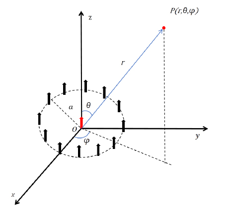
Figure 1: Diagram of the UCA.
As shown in Fig. 1, the UCA no longer transmits a single-mode vortex wave but instead uses OAM beams with a changing number of modes. The vortex radiation field generated by the UCA actually carries different orbital angular momenta.When appropriate parameters such as the number of elements,radius,and frequency are set,the generated OAM exhibits minimal field components in other modes,allowing for the production of nearly pure OAM,which will not affect the imagings quality [22]. A simulation of the proposed imaging method is carried out to demonstrate its effectiveness.
II. IMAGING MODELS
The scene geometry of the forward-looking imaging system is depicted in Fig. 2, where a UCA, located in the Cartesian coordinate system O-XYZ, moves along the X-axis with a constant velocity, transmitting vortex EM waves. In this coordinate system, the Z-axis points toward the center of the Earth, and the Y-axis is perpendicular to the X-axis, pointing to the right. The receiving antenna is positioned at the center of the UCA, which is also considered the radar’s location. The initial position of the radar motion is treated as the origin of the 3D Cartesian coordinate system O-XYZ. The target’s position is denoted as , while the radar’s position is denoted as , and the instantaneous distance between the target and the radar is represented as
| (1) |
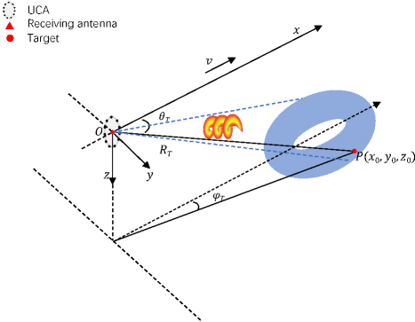
Figure 2: Imaging geometry of an OAM-based radar imaging system.
Considering that the forward-looking motion trajectory is much smaller than the imaging distance of the target, the response of the Bessel magnitude term to changes in the target’s elevation angle can be neglected. In other words, the instantaneous pitch angles between the radar and the target are assumed to be equal, i.e., . In this imaging system, the UCA no longer transmits a fixed-mode vortex EM wave. Instead, the OAM mode number varies linearly with time. The coefficient governing this linear variation is denoted as . The UCA transmits linear frequency-modulated (LFM) signals to generate vortex beams, and the transmitted signal can be expressed as:
| (2) | ||
where , , and represent the range time variable, pulse width, linear frequency modulation ratio, and center carrier frequency, respectively. Based on the above expression, the vortex SAR echo can be derived as follows:
| (3) | ||
where , and are denoted as fast time, slow time, and central wavelength, respectively. represents the slow time corresponding to the point where the carrier platform is closest to the target, and is the corresponding slant range. is the wave number, and is the target scattering coefficient. is the first type of Bessel function of order , and denotes the radius of the UCA. Additionally, and represent the distance and azimuthal envelopes, respectively, which are typically modeled using a rectangular window. is the instantaneous azimuthal angle of the target, which, according to the geometrical relationship, can be expressed as:
| (4) |
The Taylor expansion of the instantaneous azimuth expression, neglecting higher-order terms beyond the third order, is given by:
| (5) |
Due to the relationship between the OAM mode number and slow-time transformation, the new phase frequency modulation (FM) function can be obtained as follows:
| (6) |
Observing the above equation, we find that the azimuth factor term comprises two components. The first is a linear term, , representing a new single-frequency signal introduced in the azimuth direction, which can be compensated by designing an appropriate slow-time correction function. The second component is a quadratic term, , related to slow time , which manifests as a new quadratic curvature term in the traditional SAR azimuth echo.
In forward-looking SAR, azimuthal imaging faces challenges due to the minimal variation in Doppler frequency. Single-antenna SAR systems exhibit imaging blind spots, with left and right targets producing identical Doppler frequencies, leading to left-right blurring in the image. Compensation is therefore necessary to enhance azimuthal resolution in the imaging system.
The new azimuthal term derived through modal design addresses these limitations. It not only eliminates the issue of identical Doppler frequencies for left and right targets but also introduces a new linear frequency-modulated (FM) signal with a tuning frequency of . This new term, characterized by a tuning frequency , contributes to improved azimuthal resolution and minimizes imaging ambiguities.
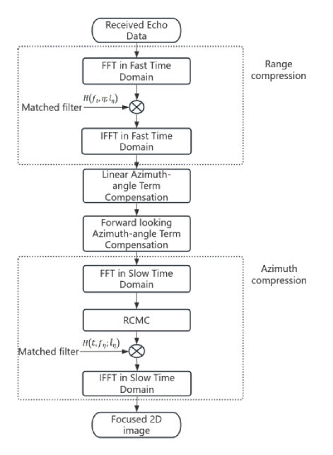
Figure 3: The flowchart of the improved RD algorithm.
III. IMAGING ALGORITHMS
Based on the above analysis and compensations, an improved RD algorithm is proposed, with the processing flow illustrated in Fig. 3. Similar to the traditional RD algorithm, range compression is performed first. Applying the range FFT to the echo signal yields:
| (7) | ||
The corresponding matched filter is designed as follows:
| (8) |
Then, the range compression result is obtained as follows:
| (9) | ||
where the range envelope .Subsequently, the linear term affecting imaging quality, as well as the azimuthal FM term of conventional forward-looking SAR, are compensated by applying a conjugate phase factor.
| (10) | ||
Next, the range walk correction factor is constructed in the frequency domain as follows:
| (11) |
By multiplying the range walk correction factor with the range-frequency and azimuth-time domain signal, the two-dimensional time-domain echo signal with corrected range walk is obtained:
| (12) | ||
Finally, the azimuth compression result is obtained through an azimuth matched filter, which is defined as follows:
| (13) |
The final 2D compressed echo can be expressed as:
| (14) |
At this stage, the 2D focused image for the proposed vortex SAR is achieved, with the azimuth compression envelope expressed as follows:
| (15) | ||
The range resolution is determined by the bandwidth of the transmitted signal, which can be expressed as:
| (16) |
The azimuthal resolution of conventional forward-looking SAR imaging depends on the antenna aperture D. However, the small angle between the target area and the trajectory direction results in minimal variation in the azimuthal Doppler frequency, leading to poor imaging quality. By introducing an OAM mode that varies over time, the new azimuthal resolution can be derived as:
| (17) |
where the newly introduced Doppler bandwidth is . This bandwidth can be adjusted by designing a linear relationship between the OAM mode number and time, thereby achieving an azimuthal resolution that meets the desired requirements.
IV. SIMULATION AND DISCUSSION
The simulation results of the proposed 2D forward-looking EM vortex imaging method are presented and analyzed in detail in this section. These results demonstrate the significant impact of the method proposed in this paper on enhancing forward-looking SAR imaging performance.To achieve higher purity of OAM and improve imaging quality, the array radius is set to [23].The other key parameters used in the simulation experiments are listed in Table 1.
Table 1: Simulation parameters
| Parameter | Value | Name |
| Flight height | m | |
| Central Frequency | 35 | GHZ |
| Bandwidth | 20 | MHZ |
| UCA radius | 0.12 | m |
| Radar flight speed | 150 | m/s |
Since the number of OAM modes generated is currently limited to integer values, can be used to obtain the actual number of OAM modes transmitted from each slow-time sampling point , where is an integer-valued function. Consequently, the number of transmitted OAM modes corresponding to the entire slow-time sampling period can be expressed as .
As shown in Fig. 4, the OAM mode curves of theoretical value and the designed value almost coincide with the slow time transition, and it can be found that the modes error is very small.This indicates the effectiveness of the OAM pattern design.
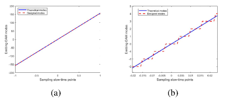
Figure 4: Comparison between the Rounded Mode Values and the Linear Mode Values.
To verify the effectiveness of the forward-looking imaging method proposed in this paper in enhancing azimuthal resolution, simulations were conducted comparing the new azimuthal Doppler frequency with that of conventional forward-looking SAR. Figure 5 shows the comparison between the azimuthal Doppler frequency with a linearity factor of and the azimuthal Doppler frequency of conventional forward-looking SAR. A clear difference can be observed between the Doppler progression of conventional forward-looking SAR and that of the modal-based design. In the conventional method, azimuthal signals can be compressed in the RD domain using matched filtering, while in the modal-based design, the Doppler slope becomes smaller as the course direction approaches a point target within the same range cell during one synthetic aperture time.
Three targets with coordinates (1000, 200), (3000, 200), and (3000, 160) were placed in the imaging scene. The imaging results, obtained using the RD algorithm for conventional forward-looking SAR, are shown in Fig. 6. These results demonstrate a left-right blurring problem in forward-looking SAR imaging, attributed to the equal Doppler frequency values generated by left and right targets with equal azimuthal coordinate magnitudes. Additionally, as the azimuth angle between the target and radar decreases, the imaging resolution of the forward-looking SAR deteriorates, leading to an inability to distinguish between closely spaced target points.
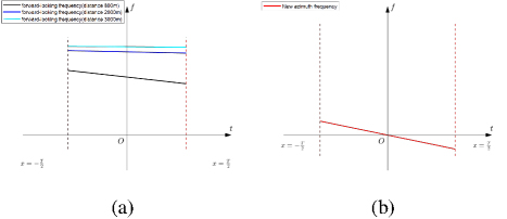
Figure 5: Azimuthal Doppler course for different distance values of forward looking SAR. (a) and new directions doppler history (b).
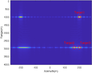
Figure 6: Forward-looking SAR 2D point target imaging.
Figure 7 presents a comparison of the azimuthal point spread function between the vortex forward-looking imaging and conventional forward-looking imaging. It is evident that the vortex forward-looking imaging demonstrates superior azimuthal resolving power at the same position, while the azimuthal resolution of conventional forward-looking imaging decreases as the distance value increases. Additionally, as shown in Fig. 8 (a) and Fig. 8 (b), the azimuthal imaging quality of conventional forward-looking SAR is significantly lower than that of the vortex forward-looking SAR. The vortex forward-looking imaging, based on modal design, achieves azimuthal resolution similar to that of forward-looking SAR.
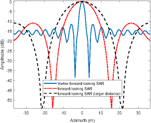
Figure 7: The azimuthal profiles of conventional forward-looking and vortex forward-looking PSF.
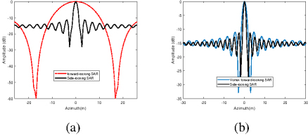
Figure 8: Imaging result after range compression. (a) Results after distance matched filtering. (b) Results after RCMC.
Three ideal scattering points are placed in the imaging scene with coordinates , , and in the O-XYZ coordinate system. By designing a linear relationship between the mode number and time, different azimuthal Doppler frequencies can be obtained. These different linear relationships, along with the corresponding azimuthal resolutions and mode number ranges, are listed in Table 2. As shown in Table 2, each linear relationship yields a distinct azimuthal resolution and associated performance index for imaging the target point P1. The radar’s azimuthal resolution performance improves significantly as the number of OAM modes increases. When , the simulated results after range compression, as shown in Fig. 9 (a), reveal two straight lines with identical tilt angles due to the forward-looking SAR trajectory. After applying the forward-looking SAR range migration correction method, the corrected results are displayed in Fig. 9 (b), where the range compression curves are no longer tilted, indicating that range migration has been effectively corrected.
Table 2: Simulation parameters
| Linear Factor | OAM Model Range | IRW (m) | ISLR (dB) | PSLR (dB) |
| 0 | ||||
| 30 | [-38,38] | 7.14 | -11.52 | -12.98 |
| 40 | [-50,50] | 5.56 | -11.58 | -13.00 |
| 50 | [-63,63] | 4.46 | -11.55 | -13.07 |
| 60 | [-75,75] | 3.74 | -11.54 | -13.27 |
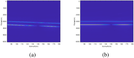
Figure 9: Imaging result after range compression. (a) Results after distance matched filtering. (b) Results after RCMC.
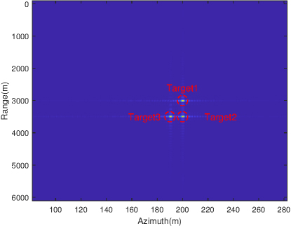
Figure 10: 2D imaging simulation results.
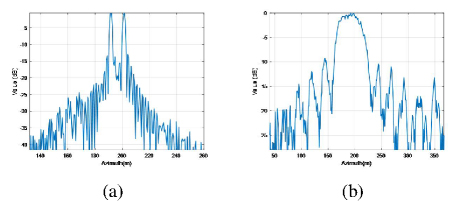
Figure 11: Comparison of imaging results. (a) Azimuthal profiles of conventional SAR. (b) Azimuthal profiles of the vortex SAR.
Finally, the 2D imaging results are obtained using the designed azimuthal matched filter, as shown in Fig. 10. The figure clearly demonstrates that the imaging quality of the target points is excellent, with high differentiation between targets. This result illustrates the effectiveness of the proposed method in suppressing target blurring and enhancing resolution.
The conventional forward-looking SAR image of the targets 1 and 2 is shown in Fig. 6, wherein the two targets cannot be distinguished from the result view.As a comparison, the same targets are processed by the vortex forward-looking SAR, and two clearly focused target points are obtained in Fig. 10. Then the two targetsazimuth profiles of the conventional SAR and the vortex SAR are exhibited in Fig. 11 (a) and Fig. 11 (b), which illustrates the vortex SAR can achieve a higher azimuth resolution,and two peak positions can accurately correspond to the set targets.However,the conventional SAR can only obtain one peak and detailed position information cannot be obtained.
In addition, the factors influencing the azimuthal resolution of forward-looking SAR are analyzed. Based on the Doppler bandwidth expression for vortex forward-looking SAR, the azimuthal resolution can be expressed as:
| (18) |
It can be observed that, when the synthetic aperture length is fixed, the azimuthal resolution of vortex forward-looking SAR imaging depends on the linear relationship of the OAM mode number, the radar speed , and the -axis coordinate value . The azimuthal resolution of vortex forward-looking SAR is influenced by radar speed. As shown in Fig. 12, for a given radar speed, the azimuthal resolution decreases as the target moves further from the beam axis, reflecting the temporal and spatial characteristics of azimuthal resolution. This compensates for the limitations of traditional forward-looking SAR in azimuthal resolution.
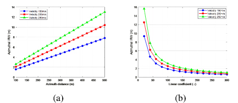
Figure 12: Analysis of factors affecting azimuthal resolution. (a) Resolution curves for different azimuthal axes for a certain radar speed. (b)Resolution curves for different linearity coefficients for a certain radar speed.
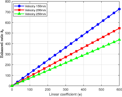
Figure 13: Azimuthal resolution enhancement ratio.
Additionally, for targets at a fixed distance, the azimuthal resolution can be significantly enhanced by increasing the linearity coefficient. However, the azimuthal resolution of the proposed vortex forward-looking SAR deteriorates as radar speed increases. In addition, the azimuthal resolution enhancement ratio between conventional forward-looking SAR and vortex forward-looking SAR can be derived from the azimuthal resolution expression in (12) as:
| (19) |
where represents the azimuthal resolution of conventional forward-looking SAR. As shown in Fig. 13, the influence curve approximates an extended straight line, indicating that the enhancement ratio increases linearly with the linearity coefficient, resulting in a significant improvement in azimuthal resolution. Additionally, the slopes of these lines vary with radar speed, confirming the effect of radar speed on the azimuthal resolution of vortex forward-looking SAR. However, due to the lower energy of higher-order OAM beams, increased mid-air divergence, and the complexity of antenna design, the proposed SAR imaging methods cannot achieve unlimited improvements in azimuthal resolution and enhancement ratio. The upper limit is currently constrained by the generation of the actual OAM pattern.
V. CONCLUSION
This paper proposes a forward-looking SAR imaging method based on orbital angular momentum (OAM) vortex EM waves to address the challenges of low azimuthal resolution and left-right target blurring in traditional forward-looking SAR imaging. First, an echo model was developed based on the characteristics of the designed OAM beam and the imaging scenario. Subsequently, a compensation method for the azimuthal term was introduced, and the RD algorithm was enhanced to achieve target range imaging through range compression and target-focused azimuth imaging through azimuth compression.
The designed OAM mode variations enable the forward-looking SAR system to achieve higher azimuthal resolution in 2D imaging and effectively distinguish between targets with identical left and right Doppler frequencies. Simulation results demonstrate that this method significantly improves the quality of forward-looking SAR azimuthal images, offering a promising solution to forward-looking imaging challenges.
While the proposed method focuses primarily on theoretical analysis and algorithm simulations, its implementation is feasible with current hardware designs. For instance, uniform circular arrays (UCA) can flexibly generate OAM beams through precise phase control. Adjusting the mode numbers requires controlling the phase shift between array elements, a capability well-supported by existing digital or analog phase control systems.
It is worth noting that generating higher-order OAM modes may introduce challenges such as increased hardware complexity and phase synchronization requirements. Nevertheless, for low- to moderate-order modes, these challenges remain manageable, enabling the proposed method to effectively enhance azimuth resolution without requiring significant hardware modifications. Future research will aim to address these challenges and further optimize the implementation process, ensuring the practicality and scalability of the approach in real-world applications.
REFERENCES
[1] M. E. Yanik, D. Wang, and M. Torlak, “Development and demonstration of MIMO-SAR mmWave imaging testbeds,” IEEE Access, vol. 8, pp. 126019-126038, July 2020.
[2] J. D. Jackson, Classical Electrodynamics, 3rd ed. New York, NY:Wiley, Aug. 1998.
[3] G. GUO, W. HU, and X. DU, “Electromagnetic vortex based radar target imaging,” Journal of National University of Defense Technology, vol. 35, no. 6, pp. 71-76, Dec. 2013.
[4] K. Liu, Y. Cheng, X. Li, and G. Yue, “Microwave-sensing technologyusing orbital angular momentum,” IEEE Veh. Technol. Mag., vol. 14, no. 2, pp. 112-118, Feb. 2019.
[5] K. Liu, Y. Cheng, and Z. Yang, “Orbital-angular-momentum-based electromagnetic vortex imaging,” IEEE AntennasWireless Propag. Lett., vol. 14, pp. 711-714, Dec. 2015.
[6] J. C. Curlander and R. N. McDonough, Synthetic Aperture Radar Sys-tems and Signal Processing, New York, NY: Wiley-Interscience, Nov. 1991.
[7] H. Bi, G. Bi, B. Zhang, and W. Hong, “Complex-image-based sparseSAR imaging and its equivalence,” IEEE Trans. Geosci. Remote Sens., vol. 56,no. 2, pp. 5006-5014, Sep. 2018.
[8] S. Li, O. Xu, W. Li, and Y. Wang, “Three dimensional SARimaging based on vortex electromagnetic waves,” Remote Sens. Lett., vol. 9, no. 4, pp. 343-352, Apr. 2018.
[9] X. Bu, Z. Zhang, and L. Chen, “Synthetic aperture radar interfer-ometry based invortex electromagnetic waves,” IEEE Access, vol. 7, pp. 82693-82700, July 2019.
[10] T. Yang, W. Huang, and X. Lu, “Two dimensional forward-looking missile-borne radar imaging based on vortex electromagnetic waves,” IEEE Access, vol. 8, pp. 221103-221110, Dec. 2020.
[11] G. A. Turnbull, D. A. Robertson, G. M. Smith, L. Allen, and M. J. Padgett, “The generation of free-space Laguerre-Gaussian modes at millimetre-wave frequencies by use of a spiral phaseplate,” Opt.Commun, vol. 127, pp. 183-188, June1996.
[12] S. Zheng, X. Hui, X. Jin, H. Chi, and X. Zhang, “Transmission characteristics of a twisted radio wave based on circular traveling-wave antenna,” IEEE Trans. Antennas Propag, vol. 63, no. 4, pp. 1530-1536, Apr. 2015.
[13] M. Alibakhshi-Kenari, M. Naser-Moghadasi, R. A. Sadeghzadeh, B. S. Virdee, and E. Limiti, “A new planar broadband antenna based on meandered line loops for portable wireless communication devices,” Radio Sci, vol. 51, no. 7, pp. 1109-11117, July 2016.
[14] S. M. Mohammadi, “Orbital angular momentum in radio A system study,” IEEE Trans. Antennas Propag, vol. 58, no. 2, pp. 565-572, Feb. 2010.
[15] K. Liu, Y. Cheng, X. Li, Y. Qin, H. Wang, and Y. Jiang, “Generation of orbital angular momentum beams for electromagnetic vortex imaging,” IEEE Antennas Wireless Propag. Lett., vol. 15, pp. 1873-1876, 2016.
[16] J. Wang, K. Liu, Y. Cheng, and H. Wang, “Vortex SAR imaging method based on OAM beams design,” IEEE Sensors Journal, vol. 19, no. 24, pp. 11873-11879, Dec. 2019.
[17] Q. Feng, Y. Lin, Y. Zheng, and L. Li, “Vortex beam optimization design of concentric uniform circular array antenna with improved array factor,” Applied Computational ElectromagneticsSociety (ACES) Journal, vol. 36, no. 7, pp. 830-837, July 2021.
[18] P. Welch, “The use of fast Fourier transform for the estimation of power spectra: A method based on time averaging over short, modified periodograms,” IEEE Trans. Audio Electroacoustics, vol. 15, no. 2, pp. 70-73, June 1967.
[19] R. Li, H. Hu, S. Lei, Z. Lin, and B. Chen, “TElevation imaging based on vortex electromagnetic wave,” in Proc. IEEE Int. Symp. Antennas Propag. USNC-URSI Radio Sci. Meeting, pp. 827-828, July 2019.
[20] A. Tennant and B. Allen, “Generation of OAM radio waves using circular time-switched array antenna,” IEEE Trans. Audio Electroacoustics, vol. 48, no. 21 pp. 1365-1366, Oct. 2012.
[21] Y. Luo, Q. Zhang, C. Qiu, S. Li, and T. Soon Yeo, “Micro-Doppler feature extraction for wideband imaging radar based on complex image orthogonal matching pursuit decomposition,” IETRadar, Sonar Navigat, vol. 7, no. 8, pp. 914-924, Oct.2013.
[22] K. Liu, H. Liu, and Y Qin, “Generation of OAM Beams Using Phased Array in the Microwave Band[J],” IEEE Transactions on Antennas and Propagation,, vol. 64, no. 9, pp. 3580-3857, Oct. 2016.
[23] S. M. Mohammadietal, “Orbital angular momentum in radioa system study,” IEEE Trans. Antenn. Propag., vol. 58, no. 2, pp. 565-572, June 2010.
BIOGRAPHIES

Gaolong Cheng received the BEng degree in electronic from Wenzheng College of Soochow University, Jiangsu, China, in 2022, and is now pursuing his MEng in electronic information at the University of Shanghai for Science and Technology, Shanghai, China. His research interests include synthetic aperture radar imaging as well as vortex radar imaging.

Ping Li received the master’s degree in electromagnetic field and microwave technology and the Ph.D. degree in circuits and systems from Northwestern Polytechnical University, Xian, China, in 2006. She is currently a Researcher with the University of Shanghai for Science and Technology, Shanghai, China. Her research interests include millimeter-wave and terahertz technology, especially the terahertz imaging systems.
ACES JOURNAL, Vol. 40, No. 5, 419–427
doi: 10.13052/2025.ACES.J.400505
© 2025 River Publishers