Ultrawideband Bowtie Slot Antenna With Defected Ground Structure
Richard S. W. Ting, Intan S. Zainal Abidin, and Azniza Abd Aziz
1School of Electrical and Electronic Engineering, Engineering Campus
Universiti Sains Malaysia, Nibong Tebal 14300, Malaysia
richardting7@gmail.com, intan.sorfina@usm.my
2Intel Microelectronics
Penang 11900, Malaysia
azizniza@gmail.com
Submitted On: December 9, 2024; Accepted On: July 4, 2025
ABSTRACT
An ultrawideband (UWB) antenna is well-suited for several applications, particularly in wireless communications, radar and sensing systems. A UWB antenna covering 1.8 GHz to 3.8 GHz is proposed in this research work. A study was conducted on a bowtie slot antenna with different combinations and shapes of defected ground structure (DGS). Different shapes of DGS were introduced to investigate the effects of DGS on the bandwidth, reflection coefficient and radiation performance of the antenna. For the bowtie slot antenna with partial ground and circular DGS, there are three resonant frequencies with lowest at 2.0 GHz (-18.5 dB), 2.5 GHz (-36.5 dB) and 3.3 GHz (-41.5 dB), while the antenna design with partial ground and dumbbell DGS has resonant frequencies at 2.0 GHz (-18.5 dB), 2.5 GHz (-36.5 dB) and 3.3 GHz (-44 dB). Upon adding a DGS structure such as a circle or dumbbell on the ground plane, the bandwidth performance of the proposed antenna was significantly enhanced. The radiation efficiency of the proposed antenna reached 80% and the directivity was 4.17 dBi (2.0 GHz), 5.58 dBi (2.5 GHz) and 5.18 dBi (3.3 GHz).
Index Terms: Bowtie slot antenna, defected ground structure, ultrawideband antenna.
I. INTRODUCTION
Ultrawideband (UWB) antennas play a crucial role in modern wireless communication, radar and imaging applications due to their ability to operate over a broad frequency range. A UWB antenna is characterized by a fractional bandwidth of greater than 20% or an absolute bandwidth exceeding 500 MHz, as defined by the Federal Communications Commission (FCC) [1]. The key advantages of UWB antennas include high data transmission rates, low power consumption and minimal interference with narrowband systems. These characteristics make them highly suitable for applications such as ground-penetrating radar (GPR), biomedical imaging and wireless body area networks (WBANs).
Among the various UWB antenna configurations, the bowtie slot antenna is a popular choice due to its simple geometry, wide impedance bandwidth and omnidirectional radiation pattern. Additionally, they are highly suitable for integration into various systems with advantages such as lightweight design, low profile and ease of manufacturing [2]. Bowtie slot dipoles are also growing in popularity due to their higher gain and bandwidth as compared to normal microstrip patch or slot antenna [3]. A monopole-like bowtie slot UWB antenna was proposed in [4] and was able to achieve a wide bandwidth of 10.43 GHz. Another proposed high gain bowtie slot antenna with miniaturized triangular shape metallic ground plane was able to achieve multiband operation and higher bandwidth [5].
A defected ground structure (DGS) is a single or limited number of slots strategically etched on the ground plane of a microwave printed circuit board to achieve a feature of stopping wave propagation over a band of frequencies [6, 7, 8]. By adding DGS to the ground plane, it is able to improve the effective line impedance, therefore, enhancing the fulfillment of the required impedance matching [4, 5, 6]. For example, some researchers used bat-shaped DGS in order to achieve good impedance matching of the antenna [9]. In [10], researchers managed to achieve UWB performance when adding DGS to its antenna design.
This paper studies and analyzes different combinations and shapes of DGS for bowtie slot antenna design operating at UWB from 1.8 GHz to 3.8 GHz. Different types of shapes and combinations of the defected structure might produce different results such narrow or wide bandwidth, directional or omnidirectional behavior and effects the resonating frequency. The paper’s outline is as follows. Section I shows the background to the research work conducted, Section II displays the design of the proposed bowtie slot antenna with different type of DGS. Section III portrays the simulated findings and discussion. The findings of the paper are concluded insection IV.
II. DESIGN OF BOWTIE SLOT ANTENNA WITH DIFFERENT DGS
In this research, UWB bowtie slot antennas were designed, simulated and optimized using CST Microwave Studio software. The targeted operating bands are from 1.8 to 4 GHz. For reference purposes, a bowtie slot antenna with full ground plane was also simulated. There were several combinations and shapes of DGS that were designed in this work: partial ground, partial ground with circular-shaped DGS and dumbbell-shaped DGS. The patch and ground of the antenna are made of copper with a thickness of 0.035 mm, while the substrate of the antenna is made of FR-4 with a thickness of 1.6 mm and 4.3.
A. Design of bowtie slot antenna
Figure 1 shows the proposed design of the bowtie slot antenna with different types of DGS. The top surface of the bowtie slot antennas consists of a bowtie-shaped slot and a microstrip feedline. The procedure for designing the bowtie-shaped slot is based on the design of bowtie antenna found in [11]. The set of design equations below is obtained by altering the semi-empirical design equations for the rectangular patches [11]. The dimensions of the proposed bowtie design are initially obtained using equations (1) to (5):
| (1) |
where
| (2) | ||
| (3) | ||
| (4) | ||
| (5) |
According to the equations, the most important dimensions in designing the bowtie slot are Bh (bigger slot width), L/2 (slot length) and Wc (smaller slot width). These three dimensions will determine the flare angle of the bowtie, which is 26∘ after optimization in 3D electromagnetics software. The amount of flaring angle will strongly affect the input impedance and bandwidth of the bowtie shaped slot [12]. The substrate thickness, relative and effective permittivity are indicated by the and respectively.
Antenna design was optimized using CST simulation software. Upon optimization, Wc is very small in the proposed design and can be considered as negligible. After the simulation and optimization process was completed, the antenna’s ground was extended larger than the antenna patch, as bigger ground improves the antenna’s reflection coefficient and radiation pattern. Other parameters for the optimized bowtie slot design are defined in Fig. 1.
In this proposed antenna, the antenna is fed by a grounded coplanar waveguide (GCPW) as shown in Fig. 1. GCPW is the modification of the CPW (coplanar waveguide) whereby it has an extra ground layer at the bottom of the antenna compared to the CPW. This structure improves the overall mechanical structure of the antenna, especially if the substrate is thin. The antenna fed by CPW has advantages of large bandwidth and simple impedance matching network [13]. The characteristic impedance of the feedline of the bowtie slot antenna with full ground is 57.01 while the characteristics impedance of the feedline of the antenna with circle-shaped and dumbbell-shaped DGS is 57.03 and 57.04 , respectively.
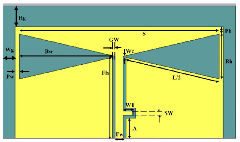
Figure 1: Proposed bowtie slot antenna with grounded coplanar waveguide feeding.
B. Defected ground structure analysis
There are four antenna designs being investigated and evaluated in this paper. Different types of shapes and combinations of the defected structure might produce different results such as narrow or wide bandwidth, directional or omnidirectional behavior and effects on the resonating frequency. In all four designs, the bowtie slot design on the top surface is maintained the same and only the bottom surface is changed, utilizing different DGS shapes and combinations. Figure 2 (a) shows the first antenna which is the reference design without any DGS on the ground plane. In the second antenna design shown in Fig. 2 (b), the ground plane is halved to solve the narrowband issue in the reference design. By removing the ground plane, the design managed to achieve high bandwidth performance as will be shown later in section III. Figure 2 (c) displays the partial ground plane design, now added with a circle-shaped DGS. Finally, Fig. 2 (d) shows the bowtie slot antenna with dumbbell DGS whereby a slot in the shape of a dumbbell is inserted at the ground plane.
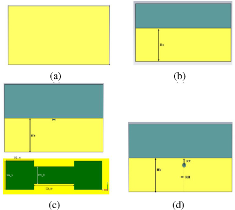
Figure 2: Evolution of DGS: (a) full ground (without DGS), (b) partial ground, (c) partial ground with dumbbell DGS, (d) partial ground with circle DGS.
Circle- and dumbbell-shaped DGS were chosen as they are simple structures, suitable for a preliminary study [14]. An equivalent circuit of a dumbbell-shaped DGS with a pair of equivalent capacitance and inductance (LC) model is shown in Fig. 3 [6]. This equivalent inductance and capacitance are contributed by two different sections of a dumbbell DGS. The conduction current surrounding the square heads produces an equivalent inductance while the gap-coupled electric fields across the narrow connecting slot results in an equivalent capacitance. The values of L, C and R are determined by the slot dimension and location of the slot [14].
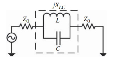
Figure 3: Equivalent LC model of a dumbbell DGS [6].
Detailed dimensions of these four antennas are shown in Table 1.
Table 1: Dimensions of bowtie slot antenna
| Dimension (mm) | Bowtie Slot Antenna | |||
| Full Ground | Partial Ground | Partial Ground with Dumbbell DGS | Partial Ground with Circle DGS | |
| GW | 1 | 1 | 1 | 1 |
| Fw | 3 | 3 | 3 | 3 |
| Fh | 29 | 29 | 29 | 29 |
| Bw | 34.5 | 34.5 | 34.5 | 34.5 |
| Bh | 16 | 16 | 16 | 16 |
| Pw | 1.5 | 1.5 | 1.5 | 1.5 |
| Ph | 2.5 | 2.5 | 2.5 | 2.5 |
| Hg | 7.5 | 7.5 | 7.5 | 7.5 |
| Wg | 4.5 | 4.5 | 4.5 | 4.5 |
| A | 7.2 | 7.2 | 7.2 | 7.2 |
| W1 | 3.4 | 3.4 | 3.4 | 3.4 |
| SW | 1.4 | 1.4 | 1.4 | 1.4 |
| Radius of circle DGS | - | 1.5 | - | - |
| Rh | - | - | - | 3 |
| Rv | - | - | - | 5 |
| Ha | - | 27.2 | - | - |
| Hb | - | - | 23.5 | 23.5 |
| CG_h | - | - | 1.5 | - |
| CG_w | - | - | 0.5 | - |
| SG_w | - | - | 0.5 | - |
| SG_h | - | - | 1 | - |
III. SIMULATION RESULTS AND DISCUSSION
A. Results and discussion
Figure 3 shows the performance comparison between the design of the bowtie slot antenna with full ground, partial ground, partial ground with circle DGS and partial ground with dumbbell DGS.
It can be seen in Fig. 4 and Table 2 that the bowtie slot antenna without DGS (full ground), which is the reference design in this study, has a reflection coefficient of -9.0 dB (2.3 GHz) and -11.0 dB (3.4 GHz). The reference design has the problem of a very narrow bandwidth at only 0.1 MHz.
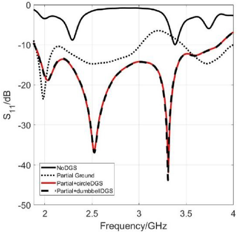
Figure 4: Comparison of simulated performance of bowtie slot antenna with different combinations of DGS.
Table 2: Summary of comparison of simulated performance of bowtie slot antenna
| Bowtie SlotAntenna | Reflection Coefficient (dB) | -10 dB Bandwidth (MHz) |
| Without DGS (Full ground) | 9.0 (2.3 GHz)11.0 (3.4 GHz) | Not sufficient0.1 |
| Partial ground | 23.5 (2.0 GHz)15.0 (2.5 GHz)15.0 (3.7 GHz) | 300850550 |
| Partial ground Circle DGS | 18.5 (2.0 GHz)36.5 (2.5 GHz)41.5 (3.3 GHz) | 2020(1.8 - 3.82 GHz) |
| Partial ground Dumbbell DGS | 18.5 (2.0 GHz)36.5 (2.5 GHz)44.0 (3.3 GHz) | 2020(1.8 - 3.82 GHz) |
Upon removing half of the ground plane, the reflection coefficient and bandwidth performance of the antenna improves as seen in the results of the design with partial ground. There are three resonant frequencies at 2.0 GHz, 2.5 GHz and 3.7 GHz with reflection coefficient of - 23.5 dB, -15 dB and -15 dB, respectively. The bandwidth of the antenna widens to 300 MHz (2.0 GHz), 850 MHz (2.5 GHz) and 550 MHz (3.7 GHz).
When the partial ground design was added with a circular slot, Fig. 4 shows a UWB performance with a total bandwidth of 2020 MHz from 1.8 GHz to 3.82 GHz. There are three resonant frequencies with lowest at 2.0 GHz (-18.5 dB), 2.5 GHz (-36.5 dB) and 3.3 GHz (-41.5 dB). Likewise, when a dumbbell slot was added to the partial ground, it shows a similar UWB performance from 1.8 GHz to 3.82 GHz with resonant frequencies at 2.0 GHz (-18.5 dB), 2.5 GHz (-36.5 dB) and 3.3 GHz (-44 dB). This shows that, by adding another circular and dumbbell slot to the partial ground plane, the surface current distribution on the ground plane was successfully disrupted and the -10 dB bandwidth of the antenna was significantly improved. The proposed UWB antenna, operating within the 1.8 GHz to 3.8 GHz frequency range, demonstrates significant potential for various wireless communication, sensing and positioning applications. In wireless communication, the antenna supports sub-6 GHz 5G covering key frequency bands such as 1.8 GHz (Band 3) and 2.5 GHz (Band 41), making it suitable for small cell networks, IoT devices and indoor coverage enhancements. Additionally, its coverage of the 2.4 GHz band enables integration with Wi-Fi (802.11n/ac), Bluetooth and Zigbee, facilitating applications in smart homes, industrial IoT (IIoT) and smart cities. Beyond communication, the antenna is well-suited for sensing and radar applications, particularly in GPR systems. It also holds promise in biomedical imaging, where UWB antennas are utilized for wireless health monitoring, breath detection and early disease diagnosis.
Figures 5-8 display the 2D and 3D radiation plots of all antenna designs. The reference antenna design has a directivity of 8.13 dBi with a half power beamwidth of 77.9∘ as can be seen in Fig. 5. The antenna exhibits a unidirectional behavior, radiating in the front of the antenna. In Fig. 6, the 2D and 3D plots of the radiation pattern of the partial ground antenna design shows a directivity of 4.8 dBi (2.0 GHz), 5.49 dBi (2.5 GHz) and 5.82 dBi (3.7 GHz), with 3 dB angular beamwidth of 90.7∘, 87.3∘ and 69.1∘, respectively. Upon removing the ground plane partially, the antenna now exhibits bi-directional behavior, radiating in front of and at the back of the antenna. It is also noted that the directivity is reduced while the half power beamwidth is slightly widened.
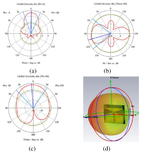
Figure 5: Simulated radiation pattern of bowtie slot antenna design with full ground (without DGS): (a) 2D plot xz plane (3.4 GHz), (b) 2D plot xy plane (3.4 GHz), (c) 2D plot yz plane (3.4 GHz), (d) 3D plot (3.4 GHz).
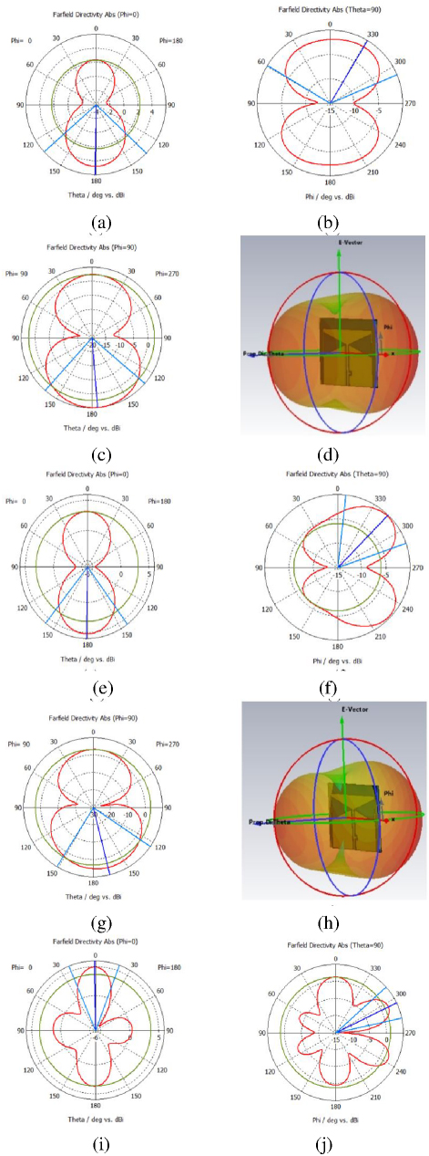
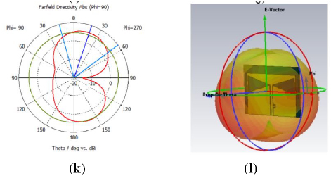
Figure 6: Simulated radiation pattern of bowtie slot antenna design with full ground (without DGS): (a) 2D plot xz plane (3.4 GHz), (b) 2D plot xy plane (3.4 GHz), (c) 2D plot yz plane (3.4 GHz), (d) 3D plot (3.4 GHz).
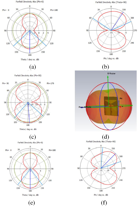
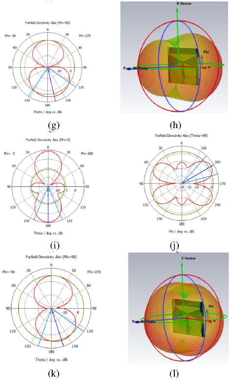
Figure 7: Simulated radiation pattern of bowtie slot antenna design with partial ground and circle DGS: (a) 2D plot xz plane (2.0 GHz), (b) 2D plot xy plane (2.0 GHz), (c) 2D plot yz plane (2.5 GHz), (d) 3D plot (2.0 GHz), (e) 2D plot xz plane (2.5 GHz), (f) 2D plot xy plane (2.5 GHz), (g) 2D plot yz plane (2.5 GHz), (h) 3D plot (2.5 GHz), (i) 2D plot xz plane (3.3 GHz), (j) 2D plot xy plane (3.3 GHz), (k) 2D plot yz plane (3.3 GHz), (l) 3D plot (3.3 GHz).
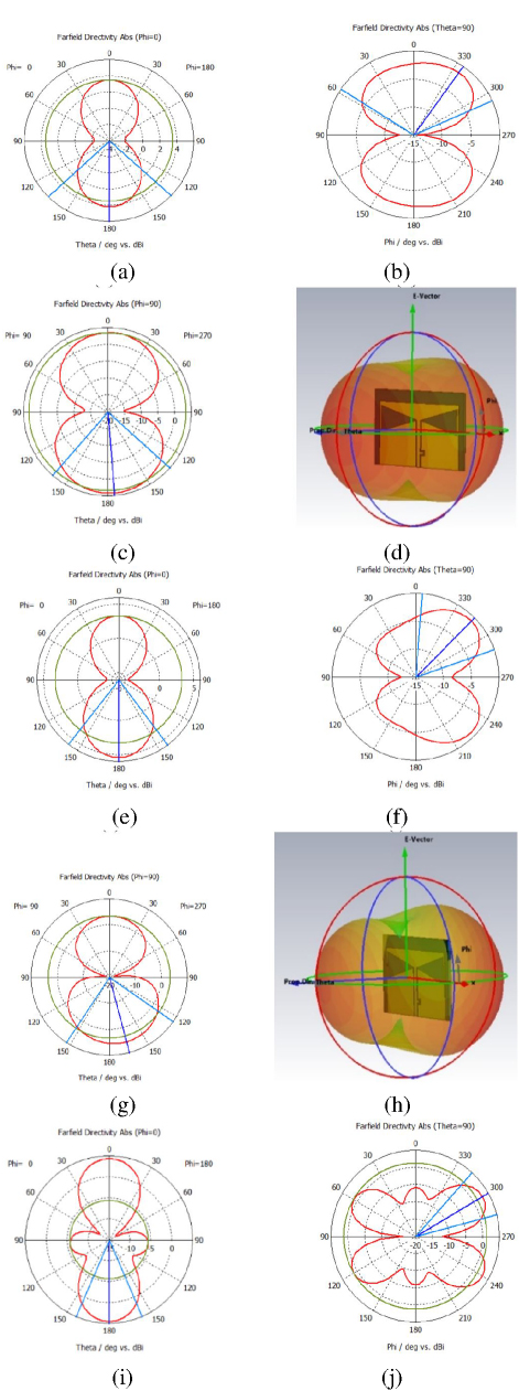
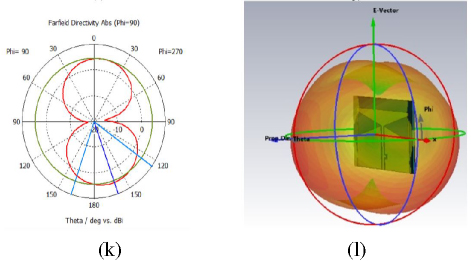
Figure 8: Simulated radiation pattern of bowtie slot antenna design with partial ground and dumbbell DGS: (a) 2D plot xz plane (2.0 GHz), (b) 2D plot xy plane (2.0 GHz), (c) 2D plot yz plane (2.5 GHz), (d) 3D plot (2.0 GHz), (e) 2D plot xz plane (2.5 GHz), (f) 2D plot xy plane (2.5 GHz), (g) 2D plot yz plane (2.5 GHz), (h) 3D plot (2.5 GHz), (i) 2D plot xz plane (3.3 GHz), (j) 2D plot xy plane (3.3 GHz), (k) 2D plot yz plane (3.3 GHz), (l) 3D plot (3.3 GHz).
Figure 7 presents the radiation pattern performance of the bowtie slot antenna with partial ground and circular DGS. The directivity performance of this particular antenna is relatively similar to the partial ground design. It has directivity of 4.17 dBi (2.0 GHz), 5.58 dBi (2.5 GHz) and 5.18 dBi (3.3 GHz) with 3 dB angular beamwidth of 89∘, 88.6∘ and 73∘, respectively. The radiation pattern performance of the bowtie slot antenna with partial ground and dumbbell DGS is also not much different from previous partial ground and circular DGS design. From Fig. 8, the directivity is 4.13 dBi (2.0 GHz), 5.34 dBi (2.5 GHz) and 4.57 dBi (3.3 GHz), with 3 dB angular beamwidth of 93.1∘, 74.8∘ and 46.6∘,respectively.
Table 3: Simulated radiation pattern performance of proposed bowtie slot antennas with different combinations of DGS
| Bowtie SlotAntenna | Operating Frequency (GHz) | Directivity(dBi) | 3 dBBeamwidth |
| Without DGS (Full ground) | 3.4 | 8.13 | 77.9∘ |
| Partialground | 2.02.53.7 | 4.85.495.82 | 90.7∘ 87.3∘69.1∘ |
| Partial ground Circle DGS | 2.02.53.3 | 4.175.585.18 | 89∘88.6∘73∘ |
| Partial ground Dumbbell DGS | 2.02.53.3 | 4.135.344.57 | 93.1∘74.8∘46.6∘ |
Overall, it is noted that the directivity and shape of the radiation pattern of all bowtie slot antenna designs with partial ground and DGS are similar. The directivity of the antenna with modified ground plane is reduced as compared to the reference bowtie slot antenna. The bowtie slot antenna traditionally is known to exhibit an omnidirectional type of radiation pattern. However, upon modifying the ground structure, bowtie slot antenna exhibit bi-directional radiation behavior, radiating on the front of and at the back of the bowtie slot antenna. Table 2 summarizes the radiation pattern performance of all four bowtie slot antenna designs proposed in this study.
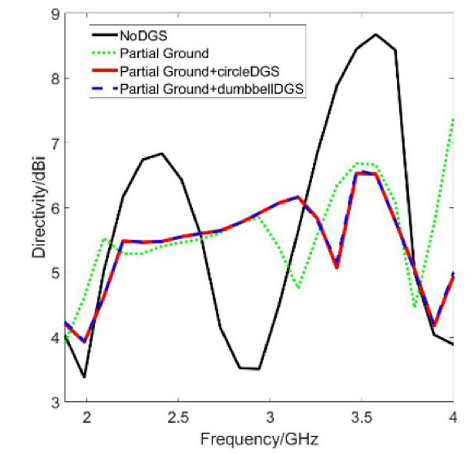
Figure 9: Simulated directivity performance of bowtie slot antenna with different DGS.
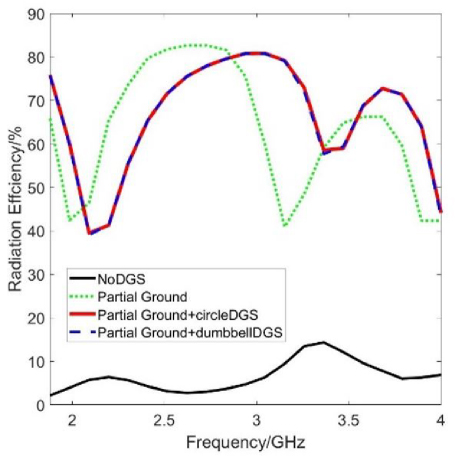
Figure 10: Simulated radiation efficiency performance of bowtie slot antenna with different DGS.
Figure 9 presents the directivity performance of all four bowtie slot antenna with different combination of DGS from 1.8 GHz to 4 GHz. This has confirmed the previous observation whereby the reference design has a higher directionality but comes with narrower bandwidth. Upon modification of the ground plane, the directivity is reduced but the antenna is able to achieve UWB performance. In Fig. 10, the simulated radiation efficiency of the bowtie slot antennas from 1.8 GHz to 4 GHz are presented. The antenna’s efficiency level is calculated using [15]. This shows that the proposed antenna incorporated with different DGS have good efficiency, being around 40-80% across the frequency band. For practical applications, having 50-60% of radiation efficiency is sufficient and is considered a good antenna [16].
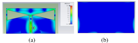
Figure 11: Simulated surface current distribution of bowtie slot antenna with full ground (without DGS): (a) top surface (3.4 GHz) and (b) bottom surface (3.4 GHz).
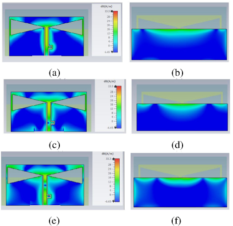
Figure 12: Simulated surface current distribution of bowtie slot antenna with partial ground: (a) top surface (2.0 GHz), (b) bottom surface (2.0 GHz), (c) top surface (2.5 GHz), (d) bottom surface (2.5 GHz), (e) top surface (3.7 GHz), (f) bottom surface (3.7 GHz).
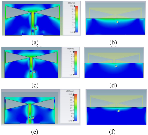
Figure 13: Simulated surface current distribution of bowtie slot antenna with partial ground and circle DGS: (a) top surface (2.0 GHz), (b) bottom surface (2.0 GHz), (c) top surface (2.5 GHz), (d) bottom surface (2.5 GHz), (e) top surface (3.3 GHz), (f) bottom surface (3.3 GHz).
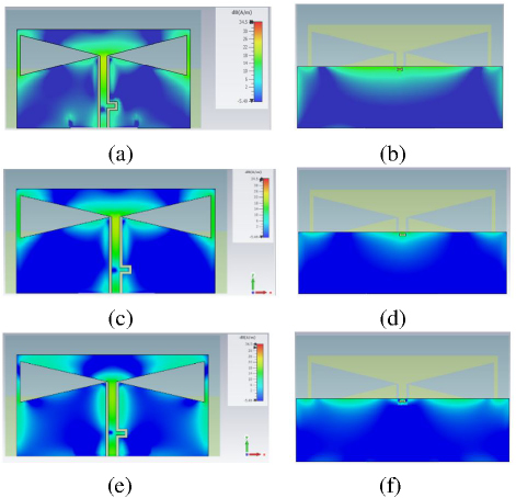
Figure 14: Simulated surface current distribution of bowtie slot antenna with partial ground and dumbbell DGS: (a) top surface (2.0 GHz), (b) bottom surface (2.0 GHz), (c) top surface (2.5 GHz), (d) bottom surface (2.5 GHz), (e) top surface (3.3 GHz), (f) bottom surface (3.3 GHz).
Figures 11, 12, 13 and 14 present the simulated surface current distribution for bowtie slot antenna without DGS, with partial ground, with partial ground and circular DGS, and with partial ground and dumbbell DGS, at their resonant frequencies. In Fig. 11, it is seen that there is a very small current flow at the right and left edges, halfway through the ground plane. Therefore, when the top half of the ground plane is removed, it enables the surface current to be concentrated along the top, left and right edges as seen in Fig. 12. This phenomenon enhances the bandwidth performance of the bowtie slot antenna significantly.
Upon adding a DGS structure underneath the feedline, such as circle and dumbbell on the ground plane, the surface current changes its movement path, flowing surrounding the defected structure, as can be observed in Figs. 13 and 14. It is known that quasi-TEM mode propagates through a conventional microstrip line with its return radio frequency current through the ground plane. By creating a defected structure on the ground, the surface current flow was successfully perturbed at the ground surface and subsequently modified the electric field and magnetic field of the antenna. As a result, it was able to significantly enhance the bandwidth performance of the proposed antenna.
Table 3 shows a comparison of the findings of the proposed bowtie slot antenna design in this paper with previously published works [5, 9, 14]. Both proposed antenna with circle and dumbbell DGS displayed excellent bandwidth performance of around 2 GHz compared to other works. The directivity of the proposed antenna is comparable to the proposed antenna of other researchers.
Table 4: Comparison of proposed antenna with previous work
| Reference | Resonant Frequency (GHz) | (dB) | Bandwidth (GHz) | Gain/Directivity (dBi) |
| [5] | 2.4 | -21.5 | 1.1 | 3.64 |
| 6.7 | -26 | 1.35 | 2.89 | |
| 10.7 | -32 | 4.1 | 2.58 | |
| 15.5 | -17.5 | 0.69 | 5.72 | |
| 17.5 | -29 | 0.2 | 6.3 | |
| [9] | 2.9 | -28.5 | 0.97 | 2.0 |
| 5.4 | -13.5 | 0.28 | 3.7 | |
| 6.1 | -17 | 0.7 | 3.7 | |
| 7 | -24 | 0.72 | 2.0 | |
| [14] | 2.29 | -12.65 | 0.1 | 5.27 |
| 3.5 | -12.89 | 0.06 | 3.2 | |
| 4.64 | -14.9 | 0.2 | 5.78 | |
| Proposed antenna with partial ground dumbbell DGS | 2.02.53.3 | -18.5-36.5-41.5 | 2.02(1.8-3.82 GHz) | 4.175.585.18 |
| Proposed antenna with partial ground circle DGS | 2.02.53.3 | -18.5-36.5-44.0 | 2.02(1.8-3.82 GHz) | 4.135.344.57 |
IV. CONCLUSION
The effects of partial ground plane with different combinations of circle-shaped and dumbbell-shaped defected ground structures (DGS) on the ultrawideband (UWB) bowtie slot antenna design were studied and compared in this paper. Two bowtie slot antenna designs were proposed with different modification to the ground plane: one with partial ground and circular DGS, the other with partial ground and dumbbell DGS. They were designed to operate from 1.8 to 3.8 GHz. The total -10 dB bandwidth is 2.02 GHz. The proposed antenna is best suited for low-band and mid-band wireless communication, UWB radar, biomedical sensing and high-accuracy localization. The DGS designs were compared with the antenna design without any DGS as a reference. For the bowtie slot antenna with partial ground and circular DGS, there are three resonant frequencies with lowest at 2.0 GHz (-18.5 dB), 2.5 GHz (-36.5 dB) and 3.3 GHz (-41.5 dB), while the antenna design with partial ground and dumbbell DGS has resonant frequencies at 2.0 GHz (-18.5 dB), 2.5 GHz (-36.5 dB) and 3.3 GHz (-44 dB). Upon adding a DGS structure underneath the feedline, such as a circle or dumbbell on the ground plane, the surface current changes its movement path, flowing surrounding the defected structure. As a result, the electric field and magnetic field was modified, leading to significantly enhanced bandwidth performance of the proposed antenna. The proposed bowtie slot antenna’s radiation efficiency is around 80%.
In conclusion, the antenna’s broad bandwidth and efficient radiation performance make it a strong candidate for next-generation wireless, sensing and security applications, with the potential for further enhancements through frequency extension beyond 4 GHz for improved 5G and future 6G capabilities.
REFERENCES
[1] Federal Communications Commission (FCC), First Report and Order: Revision of Part 15 of the Commission’s Rules Regarding Ultra-Wideband Transmission Systems, FCC-02-48, 2002.
[2] S. Mekki, C. Zebiri, D. Sayad, I. Elfergani, H. Bendjedi, J. Rodriguez, and R. A. Abd-Alhameed, “A miniaturized slot antenna with defected ground structure for GSM applications,” in IEEE 26th International Workshop on Computer Aided Modeling and Design of Communication Links and Networks (CAMAD), pp. 1-4, 2021.
[3] Z. Zeng, W. Cao, and X. Lv, “Triple-band triple-mode microstrip endfire antenna based on periodic bowtie dipoles,” in 2017 Sixth Asia-Pacific Conference on Antennas and Propagation (APCAP), pp. 1-3, 2017.
[4] S. Rashid, Y. Wu, and Y. Ding, “Monopole-like bowtie slot antenna for ultrawideband applications,” in 2016 IEEE International Conference on Computational Electromagnetics (ICCEM), pp. 376-378, 2016.
[5] Z. A. Dayo, Q. Cao, Y. Wang, P. Soothar, I. A. Khoso, G. Shah, and M. Aamir, “A compact high gain multiband bowtie slot antenna with miniaturized triangular shaped metallic ground plane,” Applied Computational Electromagnetics Society (ACES) Journal, pp. 935-945, 2021.
[6] D. Guha, C. Kumar, and S. Biswas, Defected Ground Structure (DGS) Based Antennas: Design Physics, Engineering, and Applications. Hoboken, NJ: John Wiley & Sons, 2022.
[7] N. H. Gad and M. Vidmar, “Design of a microstrip-fed printed-slot antenna using defected ground structures for multiband applications,” Applied Computational Electromagnetics Society (ACES) Journal, pp. 854-860, 2018.
[8] F. F. Ismail, M. A. El-Aasser, and N. H. Gad, “A parasitic hat for microstrip antenna design based on defected structures for multiband applications,” Applied Computational Electromagnetics Society (ACES) Journal, pp. 568-575, 2022.
[9] S. I. Naqvi, F. Arshad, and H. Tenhunen, “A bowtie slotted quad-band notched UWB antenna with defected ground structure,” Applied Computational Electromagnetics Society (ACES) Journal, pp. 1725-1730, 2019.
[10] Z. Esmati and M. Moosazadeh, “Dual band-notched small monopole antenna with bandwidth enhancement by means of defected ground structure (DGS) for UWB application,” Applied Computational Electromagnetics Society (ACES) Journal, pp. 619-625, 2015.
[11] A. C. Durgun, A. C. Balanis, C. R. Birtcher, and D. R. Allee, “Design, simulation, fabrication and testing of flexible bow-tie antennas,” IEEE Transactions on Antennas and Propagation, vol. 59, no. 12, pp. 4425-4435, 2011.
[12] S. Mukherjee, A. Biswas, and K. V. Srivastava, “Broadband substrate integrated waveguide cavity-backed bow-tie slot antenna,” IEEE Antennas and Wireless Propagation Letters, vol. 13, pp. 1152-1155, 2014.
[13] M. J. Nie, X. X. Yang, G. N. Tan, and B. Han, “A compact 2.45-GHz broadband rectenna using grounded coplanar waveguide,” IEEE Antennas and Wireless Propagation Letters, vol. 14, pp. 986-989, 2015.
[14] S. R. B. Rama and D. Vakula, “Optimized polygonal slit rectangular patch antenna with defective ground structure for wireless applications,” Applied Computational Electromagnetics Society (ACES) Journal, pp. 1194-1199, 2015.
[15] P. Miskovsky, J. M. Gonzalez-Arbesu, and J. Romeu, “Antenna radiation efficiency measurement in an ultrawide frequency range,” IEEE Antennas and Wireless Propagation Letters, vol. 8, pp. 72-75, 2009.
[16] A. Alqahtani, M. T. Islam, M. S. Talukder, M. Samsuzzaman, M. Bakouri, S. Mansouri, T. Almoneef, S. Dokos, and Y. Alharbi, “Slotted monopole patch antenna for microwave-based head imaging applications,” Sensors, vol. 22, no. 19, p. 7235, 2022.
BIOGRAPHIES

Richard Sing Wee Ting was born in Sibu, Sarawak, Malaysia, in 1996. He received the B.Eng. Degree in Electronic and Electronic Engineering from University Malaysia Sabah in 2020. His work focuses on microstrip antenna.

Intan Sorfina Zainal Abidin received her Ph.D. in Electronics Engineering from 5G Innovation Centre (5GIC), University of Surrey, Guildford, UK, in 2017. She has industrial experience working as an engineer at Motorola Solutions (M) and Celestica (M). Currently, she is a Senior Lecturer at the School of Electrical and Electronic Engineering, Universiti Sains Malaysia (USM), specializing in electronics communication system, antenna, channel propagation, RF, microwave engineering and MIMO systems. Intan is a member of IEEE.

Azniza Abd Aziz received the Ph.D. degree in electrical engineering from the University of South Carolina, Columbia, SC, USA. She is currently with Intel Corporation, Penang, Malaysia. Her current research interests include signal integrity solutions for high-speed digital design, machine learning, RF, and microwave engineering. Azniza is a Chartered Engineer (C.Eng.) conferred by the Engineering Council, UK.
ACES JOURNAL, Vol. 40, No. 7, 591–600
doi: 10.13052/2024.ACES.J.400703
© 2025 River Publishers