Dual-Beam Series-Fed MIMO Antenna With Metasurface Loading for 5G Sub-6 GHz Access Point Applications
R. Anandan1, V. Vinoth Kumar2, M. Pandi Maharajan3, and G. Jothi4
1Department of Electronics and Communication Engineering, Dhanalakshmi Srinivasan College of Engineering and Technology Mamallapuram, Chennai, Tamil Nadu, India
anandandscet@gmail.com
2Department of Electronics and Communication Engineering, Vel Tech Rangarajan Dr.Sagunthala R&D Institute of Science and Technology Chennai-600062, Tamil Nadu, India
icevinoth@gmail.com
3Dept. of ECE, Saveetha School of Engineering, Saveetha Institute of Medical and Technical Sciences Saveetha University, Chennai-602105, Tamil Nadu, India
pandimaha.net@gmail.com
4Saveetha School of Engineering, Saveetha Institute of Medical and Technical Sciences Saveetha University, Chennai-602105, Tamil Nadu, India
jothigopal1006@gmail.com
Submitted On: December 10, 2024 Accepted On: August 24, 2025
Abstract
This article presents a compact series-fed MIMO antenna integrated with metamaterial structures, designed for 5G sub-6 GHz applications. The design employs a Substrate Integrated Waveguide (SIW)-based power divider operating at 3 GHz, offering a wide bandwidth from 3 to 5 GHz. A series-fed dipole structure is realized by connecting four dipoles of varying lengths and spacing using a microstrip line, arranged symmetrically on both sides of the SIW divider. A square-ring metamaterial array is placed along the y-axis in front of the radiating elements to enhance performance. This configuration boosts the gain significantly, achieving values between 5 and 11 dB across 2.4 to 6.5 GHz, without increasing the antenna size or compromising efficiency. The metamaterial also improves polarization characteristics, reducing cross-polarization over the entire band. MIMO capability is achieved by placing two metamaterial-loaded radiators side by side, with an Electromagnetic Band Gap (EBG) structure on the ground plane to suppress mutual coupling. The proposed design is evaluated using key MIMO performance metrics, including mutual coupling, diversity gain (DG), envelope correlation coefficient (ECC), mean effective gain (MEG), and total active reflection coefficient (TARC), demonstrating its suitability for next-generation wireless systems.
Keywords: 5G antenna sub-6 GHz, dual-beam, metasurface, MIMO antenna, series-fed..
1 INTRODUCTION
The rapid evolution of wireless communication technologies has brought forth unprecedented demands on system performance, particularly in terms of data rate, coverage, and reliability [1]. Future technologies, such as augmented reality, video games, and smart cities, have a huge need for high-speed data rates [2]. In order to attain the gigabit-per-second data rate, multi-network connectivity is required [2]. In order to achieve extraordinarily high throughput, on the order of several gigabits per second, 5G communication technology has made excellent use of the cm and mm wave spectrum, which spans 3–300 GHz. Another advantage of focusing on this frequency is that other communication applications, like WLAN and Bluetooth, are able to use a smaller portion of the spectrum simultaneously [3]. The sub-6 GHz range of the 5G spectrum has garnered significant attention from researchers and professionals due to its capacity to provide highly precise and fast communication across extensive distances. The Federal Communications Commission(FCC) has allocated the frequency range of 2–6 GHz for the 5G sub-6 GHz bands inside the 5G spectrum. MIMO antennas must possess the capability to ensure minimal mutual interference between antenna elements [4]. Minimizing inter-element mutual coupling in MIMO antennas poses a significant design obstacle for antenna engineers, particularly in densely packed device environments [5, 6, 7]. In addition, a high-gain antenna lessens the impacts of multipath fading and path loss [7, 8]. A lot of recent research has focused on microstrip line and Substrate-Integrated Waveguide (SIW)-based high-gain antenna [9, 10, 11]. It operates within the frequency band of 24.5-28.4 GHz and has a gain of 7-11.4 dBi. The dipole array antenna implemented in [10, 11]. Additionally, the series-fed method has been mentioned in more recent publications as a way to improve the performance of antenna gain [12, 13, 14, 15, 16]. A challenge in enhancing gain is the increasing desire for smaller gadgets that occupy less physical space. In the last decade, metamaterials have emerged as a practical and affordable way to boost gain without significantly expanding the antenna’s physical dimensions. These composite structures can greatly enhance the gain performance of various antennas when integrated into them [16, 17]. In [16] the metamaterial is positioned in front of the series-fed antenna on the front side of the substrate to enhance the antenna’s gain. Similarly, the metamaterial is placed just above the SIW radiator, and gain is improved in [18]. In recent years, numerous MIMO antennas have been developed for sub-6GHz applications, as reported in the literature [19, 20, 21, 22]. The mutual coupling between the radiators in the MIMO antenna was reduced through a variety of decoupling structures and methods, including a defected ground, a stub-based decoupling structure, a parasitic element, and an electromagnetic band gap (EBG) [19, 20, 21, 22]. Recent advancements in high-gain antenna systems have rarely explored the integration of metamaterials within series-fed MIMO architectures, particularly for 5G sub-6 GHz applications. Addressing this gap, the present work introduces a compact metamaterial-loaded series-fed MIMO antenna capable of delivering both wide impedance bandwidth and enhanced gain. The antenna configuration utilizes a SIW-based power divider designed to operate at 3 GHz with a bandwidth extending from 3 to 5 GHz, ensuring compact and efficient signal distribution. Four dipole elements, each with tailored lengths and spacing, are symmetrically arranged along both sides of the SIW. These elements are interconnected in series using microstrip lines, forming a continuous feed network that supports wideband radiation. A metamaterial superstrate is positioned above the radiators, effectively enhancing gain without increasing the antenna’s physical dimensions. This arrangement achieves a compact, high-gain MIMO solution optimized for 5G sub-6 GHz applications.
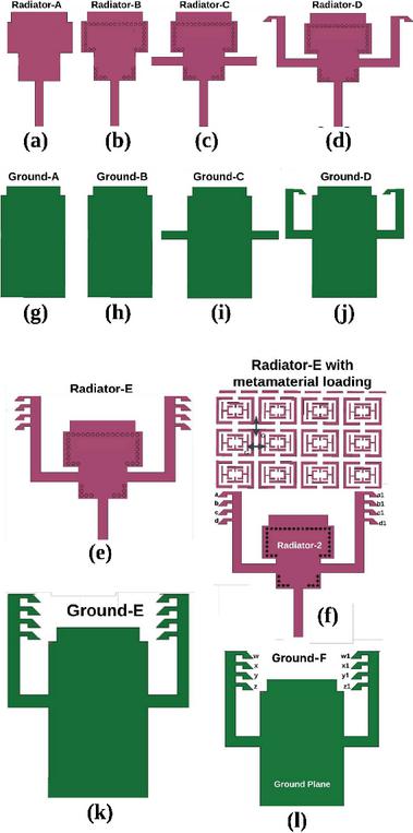
Figure 1 Development of the proposed SIW-based series-fed dipole radiator.
2 SIW-BASED SERIES-FED DIPOLE MIMO ANTENNA DESIGN
2.1 SIW-based series-fed dipole unit cell
The design of the unit cell for the series-fed dipole radiator is the starting point for the proposed series-fed dipole MIMO antenna. Initially, the rectangular radiator (Radiator-A) is fed by a single line (P1-Input) in the antenna design, as depicted in Fig. 1 (a). The reflection coefficient of the initial design (Radiator-A) is depicted in Fig. 2. As depicted in Fig. 2, the initial design is resonating at 2.8 GHz. Further, as shown in Fig. 1 (b), in Radiator (B), a metallic via (M-Via) is used to connect the top side conductor and bottom side conductor through a 0.8 mm FR4 substrate in order to construct a SIW-based power divider in the radiator. Equations (1) and (2) can be used to calculate the resonant frequency of the proposed SIW. This enables efficient power transfer from the line to the SIW. Further, two lines (P2, P3-Output ports) are connected along with the SIW-based power divider in Radiator-C as depicted in Fig. 1 (c). Because of its y-axis symmetry, the power divider can evenly divide the input power (P1) into two output port lines (P2 and P3).
| (1) | |
| (2) |
The modification is also done in the ground plane of Radiator-C by connecting two lines on the ground parallel to the front side (output ports P1 and P2) along with the x-axis. Hence, Radiator-C consists of the lines (P2 and P3) on both the top and bottom sides as depicted in Fig. 1 (g). Figure 2 depicts the reflection coefficient of Radiator-C. Due to the first-order resonance, the designed power divider operates at 3.8 GHz and has an impedance bandwidth of 4– 6 GHz, as can be illustrated.
Further, in order to improve the impedance bandwidth of the proposed radiator, Radiator-D is designed as depicted in Fig. 1 (d). Radiator-C is designed by connecting the rectangular-shaped arm along with power divider output ports P2 and P3 on the front and back sides of the substrate in the y-axis (perpendicular to the output ports P2 and P3) to connect the dipole elements. Initially, the single dipole is connected top and bottom sides along with the output port P2 and outport P3 arm. The dipole ‘a’ is connected to the left arm, whereas the dipole ‘b’ is connected to the right arm, together with P2 and P3 on the front side (radiator) of the substrate (Fig. 1 (c)). Similarly, the dipole ‘a1’ is connected to the left arm, whereas the dipole ‘b1’ is connected to the right arm, together with P2 and P3 on the backside (ground) of the substrate, as depicted in Fig. 1 (d).
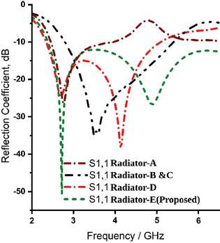
Figure 2 Reflection coefficient of the proposed series-fed dipole radiator.
A second-order resonance is introduced at the input as a consequence of this modification, which leads to an extended impedance bandwidth for the dipole antenna. Figure 2 illustrates Radiator-C’s reflection coefficient. It can be seen that the impedance bandwidth has been improved, and it operates over 2.3-5.2 GHz by Radiator-D.
Radiator-D currently does not cover the complete sub-6 GHz 5G range, thus necessitating an enhancement in the impedance bandwidth of Radiator-D. In order to further enhance the impedance bandwidth of the proposed radiator, Radiator-E is designed as shown in Fig. 1 (e). In addition, the four dipoles are interconnected on the top (radiator) and bottom sides (ground), as well as on the left and right sides, together with the output port P2 and output port P3 arm. The dipoles ‘b’, ‘c’, and ‘d’ are connected to the left arm, while the dipoles ‘a1’, ‘b1’, ‘c1’, and ‘d1’ are connected to the right arm, along with P2 and P2 located on the front side (radiator) of the substrate, as illustrated in Fig. 1 (e). Similarly, the dipoles ‘w’, ‘x’, ‘y’, and ‘z’ are connected to the left arm, whereas the dipoles ‘w1’, ‘x1’, ‘y1’, and ‘z1’ are connected to the right arm, together with P2 and P2 positioned on the bottom side (ground) of the substrate, as shown in Fig. 1 (j). In addition, the dipoles are connected with a periodic spacing of 2 mm in order to enhance the bandwidth and radiation properties. As a result of including four dipoles, the impedance of Radiator-E has experienced a significant improvement, resulting in a bandwidth of 2.3–6 GHz. Therefore, Radiator-E encompasses the complete operational range of the sub-6GHz band for 5G applications.
3 GAIN IMPROVEMENT OF THE PROPOSED SERIES-FED DIPOLE
The suggested series-fed dipole sub-6 GHz 5G antenna is designed for deployment in environments with a high degree of scattering, such as industrial factories. Due to these harsh conditions, the proposed antenna must exhibit both polarization diversity and high gain. The gain performance of the radiator is shown in Fig. 4, demonstrating values ranging from 2.5–4 dB across the 2.3–6 GHz band. Although this gain is acceptable for general environments, it is inadequate for industrial settings, where signal loss is more significant. Therefore, a gain enhancement strategy is necessary for the proposed series-fed dipole antenna. To achieve this, an SSRR-shaped metamaterial array is positioned along the y-axis in front of the radiator, as illustrated in Fig. 1 (f), enabling improved gain without increasing the antenna’s size.
3.1 Metamaterial characterization
The metamaterial unit cell that is being suggested is shown in Fig. 3 (a). The proposed metamaterial consists of an outer Rectangular Split Ring Resonator (RSRR) with a split located at the top and bottom of the RSRR. The RSRR contains two T-shaped stubs and a modified H-shaped stub, which are positioned as shown in Fig. 3 (a). Both ‘T’ and modified C-shaped stubs have a uniform thickness of 0.5 mm. Additionally, the two T-shaped stubs are positioned with a vertical axis spacing of 1 mm, while the two modified C-shaped stubs are positioned with a y-axis separation of 1 mm. The entire structure is printed on a substrate made of FR4 with a thickness of 0.8 mm, and a dielectric constant of 4.3. The characterization of metamaterial is achieved by positioning the unit cell along the x- and z-axis between two waveguide ports in CST Studio software, as shown in the Fig. 3 (a). In addition, the perfect electric conductor (PEC) and perfect magnetic conductor (PMC) boundary conditions are applied to the x-z axis for the characterization of metamaterial. The PEC boundary lies in the x-axis, and the ideal PMC boundary lies along the z-axis. It has been determined that the y-axis will propagate an electromagnetic wave that is incident normally. Transmission of the electromagnetic wave that is ordinarily incident occurs along the y-axis. In the process of establishing resonance in the transmitted and reflected waves, the resonator structure is excited by the incident waves, and electromagnetic interaction takes place within the multi-ring metamaterial unit cell. As the SIW cavity-backed antenna functions as the primary source of electromagnetic radiation propagating through the unit cells along the y-direction, the selection of the y-axis as the excitation axis for the multi-ring metamaterial unit cell is both appropriate and physically justified
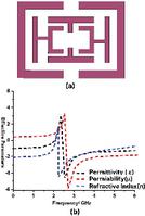
Figure 3 (a) Proposed RSRR unit cell. (b) Effective parameters of the proposed metamaterial unit cell.
The permeability, refractive index, and impedance characteristics of the proposed metamaterial unit cell is important criteria for successfully evaluating their performance characteristics. Figure 3 (b) depicts the effective parameter of the proposed RSRR metamaterial unit cell. Figure 3 (b) demonstrates that the proposed metamaterial has a negative permeability, permititivity and negative refractive index over 2.2–6 GHz. It is evident from the results that the proposed metamaterial exhibits substantial negative real non-zero Refractive Index(NZRI) and Epsilon-negative (ENG) properties over 2.2–6 GHz frequency range. Therefore, this specific frequency resonance range may be used to improve the proposed antenna gain array with dimensions of unit cells is positioned on the upper surface of the substrate in the y-direction, as shown in Fig. 1 (f). The metamaterial array maintained a gap of 1 mm between two unit cells in both the x- and y-axis.
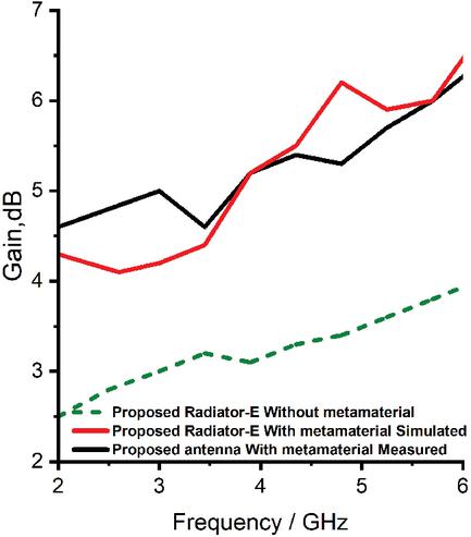
Figure 4 Gain of the proposed antenna with and without metamaterial.
Table 1 Dimensions of the proposed antenna (mm)
| Parameter | Value | Parameter | Value | Parameter | Value | Parameter | Value |
| L | 45 | LG2 | 1.9 | W2 | 1 | WG1 | 3 |
| L1 | 12.1 | LG3 | 12.1 | W3 | 2.3 | WG2 | 1.5 |
| L2 | 5.5 | LG4 | 1 | W4 | 7.3 | WG3 | 5 |
| L3 | 1.8 | LG5 | 1.2 | W5 | 7.5 | WG4 | 3.5 |
| L5 | 5 | LG6 | 18 | W6 | 3 | WG7 | 12 |
| L6 | 8.3 | LG7 | 2 | W7 | 1 | WG8 | 20 |
| L7 | 1.5 | LG8 | 2 | W8 | 1.5 | WG10 | 1 |
| L8 | 1.4 | LG9 | 1 | W9 | 1.5 | G | 1 |
| LG | 24.5 | W | 35 | W10 | 1.5 | R | 0.4 |
| LG1 | 1.4 | W1 | 10 | WG | 44 | D1 | 2 |
| D3 | 1.2 | D4 | 0.5 | D5 | 1.2 | D6 | 1 |
| D7 | 0.5 | D8 | 0.5 | D9 | 0.5 | D10 | 0.5 |
| D11 | 3 | E1 | 2.1 | E2 | 2.1 | E3 | 0.6 |
| E4 | 0.6 | E5 | 0.5 | E6 | 0.5 | E7 | 0.3 |
3.2 Impact of metamaterial
The presence of the metamaterial array has a considerable impact on the gain of the proposed antenna, but it does not have any effect on the bandwidth. The gain of the suggested antenna has been enhanced by placing the metamaterial on the y-axis, resulting in an improvement of gain from 2.5–4 dB to 4.8–7.2 dB over the frequency range of 2.3–6 GHz. Further, the simulated and measured gain of the Radiator-E with metamaterial is depicted in Fig. 4. It can be observed the proposed antenna has a measured gain of 4.3–7 dB over 2.3–6 GHz. Hence, the proposed antenna has good agreement between simulated and measured gain.
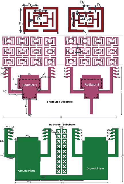
Figure 5 Proposed series-fed MIMO antenna.
4 DUAL-BEAM SERIES-FED MIMO ANTENNA DESIGN
In order to achieve link reliability and increased channel capacity in an environment with a high degree of scattering, a two-element MIMO antenna is designed with a suggested dual-beam high-gain series-fed radiator. The MIMO antenna is constructed by positioning two series-fed radiators side by side, with a common ground plane, as shown in Fig. 5. Additionally, the front side of the substrate is comprised of two series-fed radiators, while the rear side consists of a common ground and parallel running dipoles for both radiators, as depicted in Fig. 5. Further, in a series-fed radiator, the input signal is evenly divided between the two branches of the antenna, which are connected in series. The proposed antenna demonstrates a uniform distribution in the E-plane, leading to the generation of radiation with a dual-beam characteristic. Moreover, the employment of dual-beam radiation at both the transmitter and receiver significantly enhances the reliability of the link, even in the presence of obstacles that may hinder the communication. The proposed antenna demonstrates exceptional link reliability due to the utilization of MIMO technology and dual-beam characteristics. The dimensions of the proposed MIMO antenna is presented in Table 1.
4.1 EBG unit cell design
This section describes the design method for the proposed EBG unit cells. The EBG structure may suppress and allow electromagnetic propagation in a certain frequency band (Band gap), or allowed frequency band, which is determined by the structural capacitance and inductance variations of the EBG structure. Figure 6 (a) illustrates the proposed square-shaped stub EBG structure. The proposed EBG unit cell consists of a square stub and four rectangular-shaped stubs that are connected at the four sides of the square-shaped stub as depicted in Fig. 6 (a). The square stub and rectangular stub have an inductance effect. At the same time, the distance between adjacent stubs creates a capacitance effect.
| (3) | |
| (4) | |
| (5) | |
| (6) |
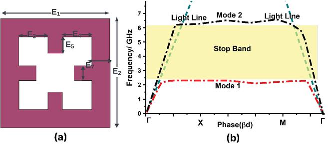
Figure 6 (a) Proposed EBG unit cell. (b) Dispersion diagram of the proposed unit cell.
As a result, the suggested square-shaped EBG unit cell performs equivalently to a stop-band LC filter. The passband may be estimated using the approximate LC values. Equations (3) and (4) are used to calculate the estimated LC values, whereas equations (5) and (6) are employed to determine the bandwidth of the proposed EBG. Furthermore, the EBG can be characterized using the dispersion diagram for a better understanding of the function. Figure 6 (b) displays the proposed unit cell’s dispersion diagram. It can be observed that the proposed EBG structure has a stop band from 2.4 to 6.4 GHz. According to the dispersion diagram, the suggested unit cell suppresses the electromagnetic wave across the frequency range 2.3–6 GHz. As a result, the suggested EBG structure may serve as a band-stop filter.
4.2 Mutual coupling reduction using EBG
The side-by-side arrangement decreased mutual coupling between radiators but not sufficient for MIMO functioning. To eliminate mutual coupling between the series-fed radiators in the proposed MIMO antenna, the proposed square-shaped element EBG decoupling structure is installed on the back side of the substrate as depicted in Fig. 5. Further, the distance between EBG elements in the x- and y-axes is 1 mm, as depicted in Fig. 5. Due to the placement of the EBG element decoupling structure, the surface current is suppressed since EBG behaves as a stop-band filter at the operating band.
5 RESULTS AND DISCUSSIONS
The photograph of the fabricated proposed MIMO antenna is depicted in Fig. 7 (a). Figure 8 (a) illustrates the simulated and measured reflection coefficient of the proposed MIMO antenna. The figure reveals that the proposed MIMO antenna exhibits a reflection coefficient of less than 10 dB between 2.2 and 6 GHz.
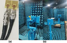
Figure 7 Photograph of the fabricated antenna and radiation pattern measurement setup of the proposed antenna in anechoic chamber.
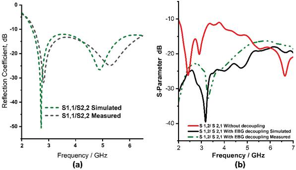
Figure 8 (a) Simulated and measured reflection coefficient comparison, (b) mutual coupling comparison.
Furthermore, Fig. 8 (b) illustrates the simulated and measured mutual coupling between the series-fed radiator in the proposed MIMO antenna. Figure 8 (b) clearly demonstrates that the proposed MIMO antenna has less than 15 dB over an operating band of 2.2–6 GHz in both simulated and measured scenarios due to EBG decoupling structure.
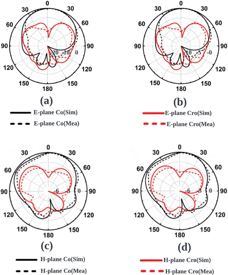
Figure 9 Radiation pattern of the proposed antenna, (a) E-plane at 2.8 GHz, (b) 5 GHz and (c) H-plane at 2.8 GHz, (d) 5 GHz.
Figure 7 (b) illustrates the radiation pattern measurement setup within the anachoic chamber. Figures 9 (a)–(d) depicts the E- and H-plane radiation patterns of the series-fed dipole MIMO antenna at 2.8 and 5 GHz. Further, the metamaterial array is placed in front of the two radiators in y-axis. The proposed metamaterial array exhibits a polarization-altering ability that effectively suppresses cross polarization in both the E-plane and H-plane within the operational band. Due to this, the suggested antenna enhances its radiation performance. Furthermore, the series-fed dipole antenna, as shown in Figs. 9 (a)–(d), achieves suppressed cross-polarization in the E-plane. In addition to that it can be observed that the proposed MIMO antenna has an omnidirectional radiation pattern in the E- and H-plane at the operating bands.
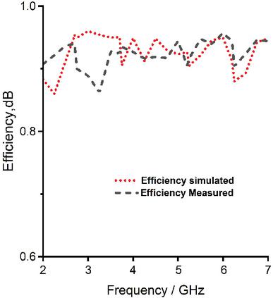
Figure 10 Efficiency of the proposed antenna.
Figure 10 illustrates the measured and simulated efficiency of the proposed MIMO antenna. The proposed MIMO antenna exhibits an efficiency of over 85% throughout the entire operating band.
5.1 MIMO parameters
5.1.1 Envelope Correlation Coefficient (ECC) and Diversity Gain(DG)
The ECC is a method used to quantify the level of coupling between various antenna elements in a MIMO antenna system. A lower ECC value, preferably less than 0.5, is associated with improved performance in diversity gain. Through the examination of far-field patterns, it is possible to ascertain the ECC performance of a MIMO antenna. In order to determine the ECC using far-field, equation (7) is employed.
| (7) |
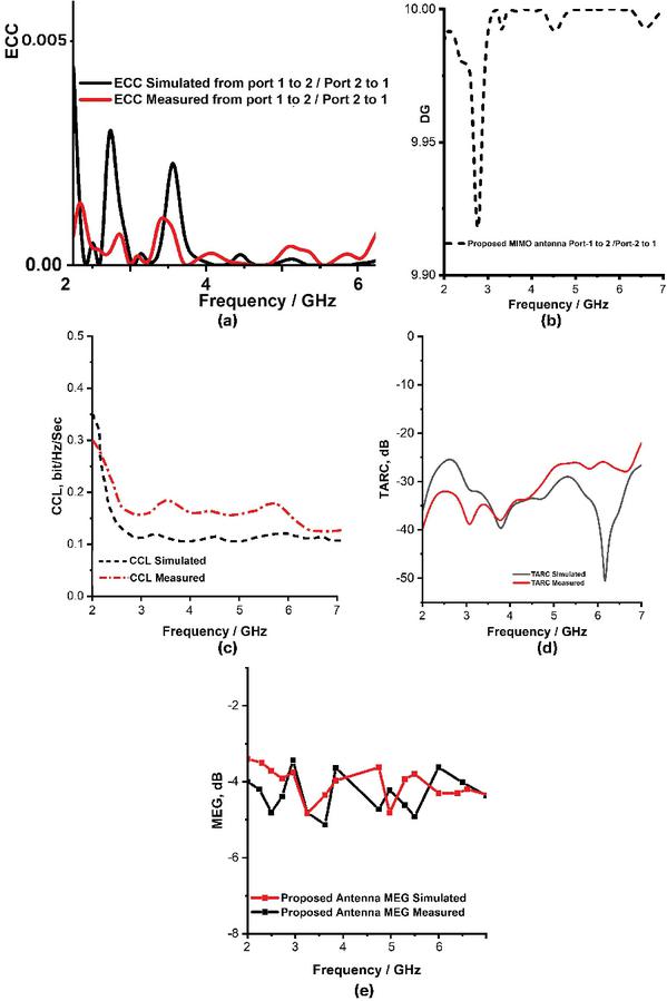
Figure 11 (a) ECC, (b) DG of the proposed MIMO antenna, (c) CCL, (d) TARC, (e) MEG of the proposed MIMO antenna.
Figure 11 (a) shows that the suggested antenna has an ECC range of less than 0.0005 over the 2.2–6 GHz frequency range, which is lower than the optimum range. It is evident from the result that the proposed MIMO antenna has less coupling between the adjacent elements due to the EBG decoupling structure.
5.1.2 Diversity gain
Diversity gain is a metric that quantifies the reduction in transmission capacity that can be achieved by employing a diversity technique while maintaining efficiency. DG can be calculated using equation (8). In order to achieve optimal MIMO performance, it is recommended that the DG for the MIMO antenna in practical scenarios be close to 10. Figure 11 (b) illustrates the DG of the proposed series-fed MIMO antenna. The suggested MIMO antenna exhibits a DG of around 10 over the whole operating frequency range.
| (8) |
Table 2 Performance comparison
| Ref. | Antenna Structure (Size mm) | Frequency (GHz) | Method |
| [16] | Dipole single antenna (112 50 3) | 18 | 1 8 array |
| [17] | Dipole single antenna (66 15 0.3) | 26 | 1 8 array |
| [19] | DRA single antenna (20.7 21.2 1.5) | 28 | 2 2 array with three layers |
| [20] | Dipole single antenna (10 36.5 0.2032) | 28 | Series-fed dipole and 8-element |
| [21] | Dipole single antenna (25 67 0.5) | 28.5 | Series-fed dipole and 6-element |
| [22] | Dipole single antenna (10 59 0.203) | 28 | Series-fed dipole and 8-element |
| [23] | Dipole single antenna (31.5 18.7 0.508) | 30.5 | Series-fed + Placing metameterial in front of the antenna |
| This Work | Dipole MIMO (45 35 0.8) | 2.2-6 | Series-fed + Placing metameterial in front of the antenna + MIMO antenna + EBG decoupling |
5.1.3 Channel Capacity Loss (CCL)
CCL is a term that refers to a variety of parameters that influence the performance of the MIMO system. It specifies the reduction in the maximum attainable data rate of the communication channel. Channel capacity of a MIMO system significantly impacts its data rate. Consequently, the channel capacity of MIMO antenna systems can be improved by minimizing the reduction in channel capacity. Channel capacity increases in a proportional manner as the number of antenna elements increases. Equation (9) can be employed to calculate CCL. In order to achieve optimal performance in MIMO systems, it is recommended that the CCL be maintained below 0.5 bits/Hz/Sec.
| (9) |
CCL of the proposed series-fed dipole MIMO antenna is illustrated in Fig. 11 (c). The suggested MIMO antenna exhibits a CCL of less than 0.3 bits/Hz/Sec across the frequency range of 2.2 to 6 GHz. Therefore, it is appropriate for achieving superior MIMO performance.
5.1.4 Total Active Reflection Coefficient (TARC)
The presence of interference among the radiators in a system with many elements deteriorates the performance of the MIMO system. The MIMO system is based on precise determination of the degree of interference. TARC can accurately measure interference between radiators. The TRAC of a two-element antenna system is determined using equation (10). In order for a MIMO system to operate effectively, it is essential to keep the TARC value below 0 dB.
| (10) | |||
The TARC of the proposed series-fed MIMO antenna is depicted in Fig. 11 (d). It can be observed from the proposed MIMO antenna that it has less than 20 dB over the 2.2–6 GHz operating band.
5.1.5 Mean Effective Gain (MEG)
A theoretical definition of MEG that takes into account all potential spatial propagation scenarios is the ratio of the average received signal strength to the average transmitted signal power.
| (11) |
The MEG of the MIMO antenna can be computed using equation (11). The MEG of the proposed series-fed MIMO antenna is depicted in Fig. 11 (e). It can be observed from Fig. 11 (e) proposed MIMO antenna has less than 3 dB over the 2.2–6 GHz operating band.
5.2 Performance comparison
Performance comparison of the proposed MIMO antenna is presented in Table 2. From Table 2 it can be observed that many series-fed antennas are implemented, but this is the first dual-beam compact metamaterial-loaded high-gain series-fed dipole MIMO antenna for sub-6 GHz 5G applications. It has a compact size of 45 35 mm, high gain 2.2–6 dBi in sub-6 GHz band, and dual beam characteristics. Therefore, the suggested MIMO antenna is a superior choice compared to the current antennas.
6 CONCLUSION
This work presents a compact series-fed MIMO antenna integrated with metamaterial structures, targeting high-gain, wideband performance in the 5G sub-6 GHz range. The antenna employs a Substrate Integrated Waveguide (SIW)-based power divider operating at 3 GHz with a 3–5 GHz bandwidth. Four dipoles of varying lengths are connected in series via microstrip lines to achieve an impedance bandwidth of 2.2–6.5 GHz. To enhance radiation characteristics without increasing antenna size, a square-ring metamaterial array is placed along the y-axis, resulting in a gain improvement from 5 to 11 dB and reduced cross-polarization. MIMO functionality is achieved by arranging two such radiators side by side, while an Electromagnetic Band Gap (EBG) structure on the ground suppresses mutual coupling. The antenna’s MIMO performance is comprehensively evaluated. ECC remains below 0.005, DG is consistently near 10 dB, and CCL is maintained below 0.4 bits/s/Hz. TARC remains under 10 dB across the band, reaching 40 dB at 3.5 GHz. MEG values range between 2.5 dB and 7 dB, indicating balanced reception. These results confirm that the proposed metamaterial-loaded MIMO antenna offers an effective, compact, and robust solution for next-generation sub-6 GHz wireless systems.
REFERENCES
[1] V. Dala-Pegorara-Souto, “Emerging MIMO technologies for 6G networks,” Sensors, vol. 23, p. 1921, 2023.
[2] R. Bajracharya, R. Shrestha, and H. Jung, “Future is unlicensed: Private 5G unlicensed network for connecting industries of future,” Sens. Switzerl, vol. 20, 2020.
[3] B. K. Ng and C. T. Lam, “Single-carrier rotation-interleaved space-time code for frequency-selective fading channels,” Appl. Sci, vol. 12(24), p. 12803, 2022.
[4] Z. Xu and C. Deng, “High-isolated MIMO antenna design based on pattern diversity for 5G mobile terminals,” IEEE Antennas Wirel. Propag. Lett, vol. 19, pp. 467–471, 2020.
[5] T. Upadhyaya, “Aperture-fed quad-port dual-band dielectric resonator-MIMO antenna for sub-6 GHz 5G and WLAN application,” Int. J. Antennas Propag, vol. 1, pp. 1–13, 2022.
[6] P. R. Girjashankar, T. Upadhyaya, and A. Desai, “Multiband hybrid MIMO DRA for Sub-6 GHz 5G and WiFi-6 applications,” Int. J.RF Microw. Comput. Eng, vol. 32, 2022.
[7] J. C. Martínez-Quintero, E. P. Estupiñán-Cuesta, and G. L. Escobar-Quiroga, “Design, analysis, and simulation of 60 GHz Millimeter Wave MIMO microstrip antennas,” J. Sens. Actuator Netw, vol. 11, 2022.
[8] K. Ding, D. M. Leenaerts, and H. Gao, “A 28/38 GHz dual-band power amplifier for 5G communication,” IEEE Trans. Microw. Theory Tech, vol. 70, pp. 4177–4186, 2022.
[9] A. Desai, Y. F. Tsao, and H. T. Hsu, “High gain substrate integrated waveguide antenna with enhanced bandwidth for millimeter-wave wireless network applications,” Wirel. Netw, vol. 29, pp. 2251–2260, 2023.
[10] J. Wang, X. Zhao, Y. Ye, and S. Liu, “A millimeter-Wave ultrawideband tightly coupled dipole array antenna for vehicle communication,” IEEE Antennas Wirel. Propag. Lett, vol. 21(10), pp. 2135–2139, 2022.
[11] S. Kadiyam and A. J. Rani, “Design and analysis of a high gain millimeter-mave antenna array for dual purpose applications,” Wirel. Pers. Commun, vol. 130, pp. 593–607, 2023.
[12] H. Wang, K. E. Kedze, and I. Park, “A high-gain and wideband series-fed angled printed dipole array antenna,” IEEE Trans. Antennas Propag, vol. 68, pp. 5708–5713, 2020.
[13] N. K. Maurya, M. J. Ammann, and P. Mcevoy, “Series-fed omnidirectional mm-wave dipole array,” IEEE Trans. Antennas Propag, vol. 71, no. 2, p. 1330, 2023.
[14] S. K. Duddu and J. Kumar, “High-gain series-fed-planar millimetre-wave Franklin antenna array,” Arab. J. Sci. Eng., vol. 49, pp. 6331–6341, 2024.
[15] T. Ma, J. Ai, M. Shen, and W. T. Joines, “Design of novel broadband endfire dipole array antennas,” IEEE Antennas Wirel. Propag. Lett, vol. 16, pp. 2935–2938, 2017.
[16] B. A. F. Esmail, S. Koziel, and A. Pietrenko-Dabrowska, “Wideband high-gain low-profile series-fed antenna integrated with optimized metamaterials for 5G millimeter wave applications,” Sci Rep, vol. 14, pp. 185–192, 2024.
[17] Z. Wani, M. P. Abegaonkar, and S. K. Koul, “High-low-epsilon biaxial anisotropic lens for enhanced gain and aperture efficiency of a linearly polarized antenna,” IEEE Trans. Antennas Propag, vol. 68, pp. 8133–8138, 2020.
[18] A. Gorai, A. Deb, and J. R. Panda, “Millimeter wave/5G multiband SIW antenna with metasurface loading for circular polarization and bandwidth enhancement,” J Infrared Milli Terahz Waves, vol. 43, pp. 366–383, 2022.
[19] R. Khan, W. T. Sethi, and W. A. Malik, “Enhancing gain and isolation of a quad-element MIMO antenna array design for 5G sub-6 GHz applications assisted with characteristic mode analysis,” Sci Rep, vol. 11111(14), pp. 1–20, 2024.
[20] H. Ahmed, X. Zeng, H. Bello, Y. Wang, and N. Iqbal, “Sub-6 GHz MIMO antenna design for 5G smartphones: A deep learning approach,” AEU - International Journal of Electronics and Communications, vol. 168, p. 154716, 2023.
[21] N. P. Kulkarni, N. B. Bahadure, P. D. Patil, and J. S. Kulkarni, “Flexible interconnected 4-port MIMO antenna for sub-6 GHz 5G and X band applications,” AEU - International Journal of Electronics and Communications, vol. 152, p. 154243, 2022.
[22] A. Desai, M. Palandoken, I. Elfergani, I. Akdag, C. Zebiri, J. Bastos, J. Rodriguez, and A. Raed, “Transparent 2-element 5G MIMO antenna for sub-6 GHz applications,” Electronics, vol. 11, no. 2, pp. 251–251.
BIOGRAPHIES

R. Anandan, Associate Professor and Head, Department of Electronics and Communication Engineering, Dhanalakshmi Srinivasan College of Engineering and Technology, India, completed his Ph.D. in the Faculty of Information and Communication Engineering from Anna University Chennai in May 2023. His interest includes antenna, optical communication, satellite communication, digital electronics, and wireless communication. He has published seven papers in international conferences and national conferences and four papers in international journals with good impact factors.

V. Vinoth Kumar, Assistant Professor, Department of Electronics and Communications, Vel Tech High Tech Dr Rangarajan Dr Sakuntala Engineering College, India. He completed his Ph.D. at the Faculty of Information and Communication Engineering from Anna University Chennai in May 2022.

M. Pandi Maharajan, Associate Professor, Department of ECE, Saveetha School of Engineering, Saveetha Institute of Medical and Technical Sciences, India. He completed his Ph.D. in the Faculty of Information and Communication Engineering from Anna University Chennai in May 2020.

G. Jothi received the B.E. and M.E. degrees in Computer Science Engineering from the Anna University Chennai, India. She is adjunct professor in ECE at Saveetha School of Engineering, Saveetha Institute of Medical and Technical Sciences, Chennai.
ACES JOURNAL, Vol. 40, No. 10, 1045–1054
DOI: 10.13052/2025.ACES.J.401010
© 2025 River Publishers