SIW Cavity-backed Gain-enhanced Circularly Polarized Metamaterial-loaded Dual-band MIMO Antenna for WLAN and 5G Applications
Infant Leo S, G. Aloy Anuja Mary, A. Syed Mazhar, Satyam Mishra, and G. Jothi
1Department of Electrical, Electronics and Communication Engineering, Galgotias University
Gautam Buddh Nagar, Greater Noida, Uttar Pradesh, India
infant.s@galgotiasuniversity.edu.in, syed.mazhar@galgotiasuniversity.edu.in, mishra.satyam@galgotiasuniversity.edu.in
2Department of Electronics and Communication Engineering, School of Electrical and Communication, Vel Tech Rangarajan Dr.Sagunthala R&D Institute of Science and Technology, Avadi, Chennai-600062, India
draloyanujamary@veltech.edu.in
3Saveetha School of Engineering, Saveetha Institute of Medical and Technical Sciences
Chennai, Tamilnadu, India
jothigopal1006@gmail.com
Submitted On: December 11, 2024; Accepted On: March 14, 2025
ABSTRACT
This work proposes the development of a metamaterial-loaded circularly dual-band cavity-backed substrate integrated waveguide (SIW) MIMO antenna designed for the sub-6 GHz, emphasizing sub-6 GHz 5G and WLAN applications. The creation of dual operating bands is enabled via a modified dual split ring resonator (CSRR)-shaped slot that is etched into the SIW cavity-backed rectangular radiator. Additionally, the antenna incorporates 6x3 modified SSRR unit cells strategically located in front of the intended radiators along the y-axis. This arrangement enables circular polarization and enhances the gain of the proposed radiator at 3.3 GHz and 5 GHz. The metamaterial loading of the proposed antenna yields a gain of 5.5 dB at 2.4 GHz and 5.4 dB at 5 GHz. Further, the implementation of a CSRR electromagnetic bandgap (EBG) decoupling structure reduces the mutual coupling between the radiators. The antenna exhibits an exceptional diversity performance. The experimental validation of the system confirms its intended functionality.
Index Terms: 5G sub-6 GHz, circularly polarized, gain enhancement, metasurface, MIMO antenna, SIW cavity.
I. INTRODUCTION
There is a notable need for improved data transmission capacity and link reliability in the current 5G age of wireless communication technology, as wireless devices are progressing at a rapid pace [1]. Among the several methods proposed by researchers to meet demand, MIMO technology has emerged as a highly effective means of improving data rates [2]. Without utilizing extra resources, MIMO antennas (multiple-input multiple-output) can increase channel capacity and link dependability [2]. Circularly polarized antennas, in contrast, have small propagation losses because they efficiently combat multipath fading [3]. This is why modern wireless networks can’t function without circularly polarized MIMO antennas. Although wideband MIMO antennas with circular polarization have been created, modern communication systems are better served by multi-band antennas with circular polarization [3]. The literature reports a plethora of methods for achieving circular polarization. Circular polarization can be achieved by strategically placing a patch on top of differently shaped slots, as described in [4, 5]. In [6, 7], the circular polarization is achieved by means of a metamaterial superstate. Many design considerations also need to be satisfied in order to achieve compact dimensions, excellent gain, and minimized mutual coupling.The literature has been updated with a variety of MIMO antennas that have been introduced by researchers in recent years [6, 7, 4]. The literature states that in order to achieve a reduction in mutual coupling, it is necessary to place an electromagnetic bandgap (EBG), parasitic elements, a rectangular stub, a various shape decoupling structure, and metamaterial [8, 9]. Over the past decade, a novel technology called substrate integrated waveguide (SIW) cavities has emerged, offering an extensive range of applications and innovative strategies for several existing applications [10, 11]. The SIW cavity-backing architecture, positioned near the edge of the ground plane structure, has significantly reduced back lobe radiation and unwanted surface currents. Thus, it enhances antenna gain while maintaining a compact form factor and providing excellent cost-effectiveness. Conventional SIW cavity-backed slot antennas exhibit significant challenges due to their limited operating bandwidth and substantial size. Researchers have explored many ways over several years to enhance the bandwidth of the SIW cavity-backed slot antenna. The enhancement in bandwidth is achieved by exciting two closely placed mode combinations, with adjustments made to the cavity modes. This facilitates an enhancement of the bandwidth. Tuning of the cavity’s position, dimensions, and slot size is necessary to optimize the cavity modes [12]. The implementation of shorting vias [12] and the slot ring [13] aims to enhance the bandwidth of the SIW antenna.
In environments with significant dispersion, such as industries, a high-gain antenna is essential. The antenna’s gain is improved by the utilization of multi-layer substrates [14] and metamaterials [15] as reported in the literature. A challenge in enhancing gain is the increasing desire for smaller gadgets that occupy less physical space. Metamaterials have recently emerged as a feasible and economical approach to enhance gain without significantly increasing the physical dimensions of the antenna. Metamaterials are a unique class of synthetic compounds that exhibit extraordinary properties that are not found in organic substances. The integration of metamaterials into various antennas substantially enhances antenna gain performance [16]. The metamaterial array is situated in front of the antenna to boost the gain [16, 17]. Furthermore, the antenna gain is improved by placing the metamaterial array above the antenna [18]. The antennas that have been listed above illustrate a variety of methods for circularly polarized MIMO antenna implementation, mutual coupling reduction, bandwidth enhancement, and gain enhancement; however, there are only a few sub-6 GHz MIMO antennas that are now available that provide a wider bandwidth with a higher gain in a compact-sized planar configuration. Further, the mentioned antennas used a metamaterial layer superstate for gain improvement, but this method makes antennas bulky. In this work, the development of a metamaterial-loaded circularly dual-band cavity-backed SIW MIMO antenna designed for the sub-6 GHz frequency is emphasized, focusing on sub-6 GHz 5G and WLAN applications.
II. MIMO ANTENNA CONFIGURATION AND ITS DEVELOPMENT
A. SIW cavity-backed radiator development
Figure 1 (a) illustrates the arrangement of the proposed SIW cavity-backed slot antenna (Antenna-1). The design incorporates a rectangular SIW cavity, formed by arranging metal vias in a rectangular pattern, as illustrated in Fig. 1 (a). The traditional rectangular SIW cavity-backed antenna is designed with metallic vias to prevent electromagnetic energy leakage. The SIW standards require that the pitch distance (s) and diameter (d) of metallic vias maintain the ratios and . According to the information presented in [10], the dimensions of the rectangular cavity resonator have been estimated using Equation (1), leading to a first-order mode (i.e., TE110) resonance at approximately 3.4 GHz, as illustrated in Fig. 1 (f):
| (1) |
where L SIW cavity length, W SIW cavity width, and C and are the velocity of light and the dielectric constant, respectively. The m, n, and p are mode indices.
A shorting pin is placed 3 mm from the left side and 8 mm from the top wall of the SIW cavity radiator to improve its bandwidth, as illustrated in Fig. 1 (a). The shorting pins establish a short circuit within the current path, leading to resonance. The increase in bandwidth is achieved by exciting two hybrid modes: resonance from the SIW cavity and shorting pins placed in close proximity to one another. The proposed SIW cavity-backed antenna features two slots designed to produce dual-band resonant frequencies: the outer ring Circular Split Ring Resonator(CSRR) slot and the inner ring CSRR slot. The integration of the inner and outer CSRR slots results in a reduction in series inductance while concurrently introducing series capacitance within the cavity circuit.
Antenna-2 has an outer ring CSRR slot positioned near the center of the side cavity, as illustrated in Fig. 1 (b). The resonant frequency of the CSRR outer ring slot can be calculated using the following equation:
| (2) |
The placement of the CSRR outer ring slot significantly influences the current path of the first-order resonance mode (TE110), leading to a modified first-order mode (TE110) that shifts the resonant frequency from 3.4 GHz to approximately 2.5 GHz due to reactive loading, as illustrated in Fig. 1 (f). Consequently, the outer ring CSRR slot effectively regulates the lower resonance frequency (2.4 GHz) of the proposed antenna. The inner CSRR slot is removed from the center of the cavity within the outer ring CSRR in Antenna-3, as illustrated in Fig. 1 (c). The resonant frequency of the CSRR outer ring slot can be calculated using the following equation:
| (3) |
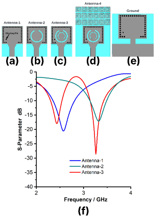
Figure 1: (a)-(e) Development of the proposed SIW cavity-backed radiator, (f) Reflection coefficient of the proposed antenna.
The placement of the inner CSRR ring slot significantly influences the current path of the first order-resonance mode (TE110), resulting in a slight modification of the TE110 mode resonant frequency from 2.5 GHz to 2.41 GHz for WLAN applications. Additionally, the inner ring CSRR slot produces a second-order resonance mode (TE120) at 3.3 GHz as a result of the reactive loading from the CSRR slot, as illustrated in Fig. 1 (f). Ultimately, Antenna-3 exhibits a hybrid mode (TE110 and TE120) at frequencies of 2.4 and 3.3 GHz, suitable for WLAN and sub-6GHz 5G applications. The SIW cavity dual slot antenna is excited by a 50 feedline to function at frequencies of 2.4 GHz and 3.3 GHz. The lumped element equivalent circuit of the proposed SIW cavity-backed antenna is illustrated in Fig. 2 (a). The equivalent circuit of the SIW cavity, outer CSRR slot, and inner CSRR slot with conductor is illustrated in Fig. 2 (a). The equivalent circuit diagram illustrates that the metallic vias are influenced by inductance. The connection between the transmission line and the SIW cavity provides the coupling capacitance and coupling inductance. Additionally, the parasitic capacitance and inductance of the transmission line are represented by Cr and Lr. The outer CSRR ring slot is governed by the parallel lumped elements R, L, and C, while the inner CSRR ring slot is similarly governed by the parallel lumped elements R, L, and C.
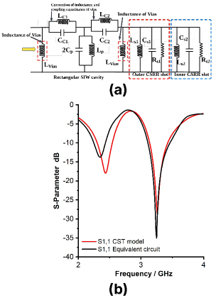
Figure 2: Lumped equivalent circuit of proposed SIW cavity antenna, (b) Reflection coefficient of the proposed antenna for CST model and equivalent circuit model.
The proposed SIW cavity-backed slot antenna is analyzed through the simulation of its lumped equivalent circuit using NI AWR Microwave Office software. The S-parameter of the lumped equivalent circuit of the proposed SIW cavity antenna is compared with the S-parameter of the CST model of the proposed SIW cavity antenna in Fig. 2 (b). Figure 2 (b) indicates that the proposed antenna operates at frequencies of 2.4 and 3.3 GHz for both the CST model and the equivalent circuit model. Thus, the performance of the CST model and the lumped equivalent circuit model is equivalent.
B. Metamaterial for gain enhancement and circular polarization conversion
The proposed antenna is intended for industrial WLAN and sub-6GHz 5G applications. Therefore, an antenna with standard gain and polarization is insufficient for this type of factory environment due to the high path loss. Therefore, an antenna with high gain and circular polarization is necessary for environments with significant path loss. This work introduces the metamaterial loading method to achieve high gain and circular polarization. The proposed Square Split Ring Resonator(SSRR) metamaterial unit cells are illustrated in Fig. 3 (a). The proposed SSRR metamaterial unit cell comprises an outer square ring stub and an inner square ring stub, which together provide an inductive effect, as depicted in Fig. 3 (a). Additionally, a 0.5 mm slot is removed at each corner of the outer square ring stub to generate a capacitive effect. As depicted in Fig. 3 (a), a 0.5-thickness stub is connected at the midpoint of both the inner and outer square ring stubs in vertical and horizontal orientations, which produces an inductive effect. The rectangular stub intersects both the inner and outer ring stubs at the center, as illustrated in Fig. 3 (a). In order to conduct the performance study of the metamaterial, the unit cell of the metamaterial is positioned between two waveguide ports. Additionally, multiple boundary conditions, including perfect electric conductor (PEC) and perfect magnetic conductor (PMC), were applied along the xz axis. The complete characterization is conducted using CST Microwave Studio software. The incident electromagnetic waves typically propagate along the y-axis. The placement of the antenna regulates the y-axis stimulation of the metamaterial structure, subsequently influencing the transmission of electromagnetic waves via metamaterial.
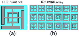
Figure 3: (a-b) Proposed SSRR metamaterial unitcell.
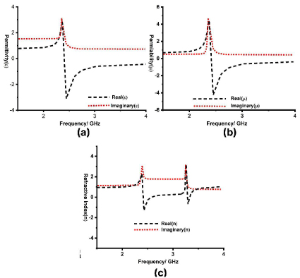
Figure 4: (a) Permittivity, (b) Permeability, and (c) Refractive index of SSRR unitcell.
The permeability, permittivity, and refractive index are essential parameters for accurately assessing the performance characteristics of the suggested SSRR metamaterial unit cell. The permittivity, permeability, and refractive index of the proposed metamaterial unit cell are illustrated in Figs. 4 (a-c). Figures 4 (a-c) demonstrate that the proposed metamaterial shows a negative real near-zero refractive index (NZRI) and epsilon-negative (ENG) characteristics at frequency ranges of 2.4 GHz and 3.3 GHz. The results clearly demonstrate that the proposed SSRR metamaterial shows near-zero properties within the operational bands (2.4 and 3.3 GHz). As a result, the designated operating frequency range (2.4 and 3.3 GHz) can be employed to enhance gain and adjust the polarization of the proposed antenna. The 6 × 3 array of modified Square Split Ring Resonator (SSRR) is depicted in Fig. 3 (b). The proposed design incorporates a metamaterial comprising a 6 × 3 array of modified Square Split Ring Resonator (SSRR) unit cells. It is printed in front of the antenna in the y-direction as depicted in Fig. 1 (d). The periodic distance of 0.5 mm is maintained in both the x and y directions between two SSRR unit cells.The y-axis is the orientation of an electromagnetic wave that is propagating normally. The y-axis corresponds to the normal path of the electromagnetic wave’s incidence. Electromagnetic interactions within the modified SSRR metamaterial unit cell, triggered by the incident waves, produce resonance in the transmitted and reflected waves. Since the electromagnetic wave enters the modified SSRR metamaterial unit cells via the SIW cavity-supported antenna and travels in that direction, the y-axis makes it easier to excite the modified SSRR metamaterial unit cell.
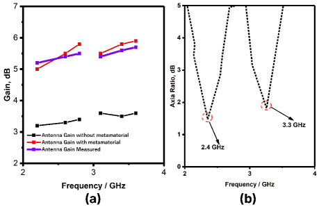
Figure 5: (a) Gain of the the proposed radiator with and without metameterial, and (b) Axial ratio of the proposed radiator with and without metamaterial.
The antenna’s gain, with and without metamaterial, is illustrated in Fig. 5 (a). Figure 5 (a) reveals that the suggested antenna demonstrates gains of 3.2 dB and 2.6 dB at frequencies of 2.4 GHz and 3.3 GHz, respectively. The suggested antenna demonstrates a gain of 6.1 dB at 2.4 GHz and 6.5 dB at 3.3 GHz, following the integration of the metamaterial unit cells. The gain of the proposed antenna with SSRR metamaterial loading has been significantly improved without modifying the resonant frequencies, as illustrated in Fig. 5 (a). Moreover, the metamaterial generally has the capacity to modify polarization. The suggested metamaterial unit cells are situated in the y-direction in front of the antenna, facilitating the conversion of linear polarization into circular polarization. The suggested metamaterial functions as a linear-to-circular polarization converter at the 2.4 and 3.3 GHz bands, as evidenced by the axial ratio characteristic illustrated in Fig. 5 (b). The axial ratio of the proposed antenna exceeds three decibels at all operational frequencies (2.4 and 3.3 GHz), as illustrated inFig. 5 (b).
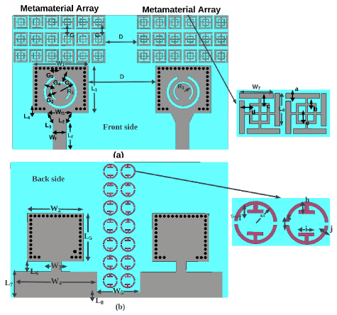
Figure 6: Proposed MIMO antenna without and with SIW cavity backed parasitic stub decoupling structure (a) Front side, and (b) Back side of the substrate.
C. Two-port SIW cavity-backed high-gain circularly polarized MIMO antenna design
For the purpose of facilitating communication in an environment that has a considerable path loss due to scattering, the antenna ought to have a high channel capacity, a high gain, and a good link reliability. This led us to propose the two-port SIW cavity-backed gain improved circularly polarized metamaterial-loaded dual-band MIMO antenna as a potential solution for usage in WLAN and sub-6GHz 5G applications in industrial environments. As depicted in Fig. 6, the SIW cavity-backed gain increased the circularly polarized metamaterial-loaded dual-band MIMO antenna that has been presented is designed by positioning two SIW-based metamaterial-loaded radiators in close proximity to each other so that they share a common ground plane. The adjacent positioning of the proposed radiator enhances the mutual connection between the suggested SIW cavity-backed radiators. Nevertheless, the mutual coupling among the radiators requires further enhancement to optimize MIMO performance. There is a necessity for a distinct decoupling structure between the proposed SIW cavity-backed radiators. An EBG structure can inhibit the transmission of electromagnetic waves within specific frequency ranges, termed the band gap. The EBG exhibits band stop filter characteristics across the band gap, enabling its application as a decoupling structure in MIMO antennas. Therefore, to diminish the reciprocal coupling between the radiators in the proposed MIMO antenna, a unique EBG decoupling structure is presented in Fig. 7 (a). The unit cell of the proposed modified CSRR EBG structure is seen in Fig. 7 (a). The proposed EBG decoupling structure is constructed by using modified CSRR ring stubs as depicted in Fig. 7 (a). As depicted Fig. 7 (a), two T-shaped stubs are connected along with modified CSRR of the EBG unit cell.
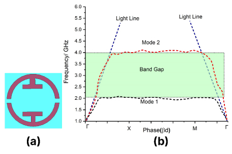
Figure 7: (a) Proposed modified Circular Split Ring Resonator EBG unit cell, and (b) Dispersion diagram of the proposed CSRR EBG unit cell.
Table 1: Dimension of the proposed antenna
| PD | PD | PD | PD |
| L40 | LG21.9 | W21 | WG13 |
| L112.1 | LG312.1 | W32.3 | WG21.5 |
| L25.5 | LG41 | W47.3 | WG35 |
| L31.8 | LG51.2 | W57.5 | WG43.5 |
| L55 | LG618 | W63 | WG712 |
| L68.3 | LG7y2 | W71 | WG8y20 |
| L71.5 | LG82 | W81.5 | WG10y1 |
| L81.4 | LG91 | W91.5 | G1 |
| LG24.5 | W35 | W101.5 | R0.4 |
| LG11.4 | W1y10 | WG44 | D12 |
| D31.2 | D40.5 | D5y1.2 | D61 |
| D7y0.5 | D80.5 | D90.5 | D100.5 |
| D113 | E12.1 | E22.1 | E30.6 |
| E40.6 | E50.5 | E60.5 | E7y0.3 |
The characterization of the proposed EBG unit cell is conducted using CST Studio software. To effectively analyze the features of the proposed EBG unit cell, the dispersion diagram of the EBG can be utilized. The dispersion diagram of the proposed EBG unit cell is illustrated in Fig. 7 (b). Figure 7 (b) indicates that the proposed EBG unit cell functions as a stop band within the frequency range of 2.2 to 4 GHz. Consequently, throughout the 2.2-4 GHz frequency range, the EBG unit cell functions as a stop-band filter. The electromagnetic waves propagate from one radiator to another while both radiators are simultaneously energized. To alleviate this issue, the suggested 7x2 EBG unit cells are positioned on the rear side of the substrate, above the ground plane, situated between the two SIW cavity-backed radiators, as illustrated in Fig. 6 (b). The positioning of the EBG unit cell facilitates the absorption of surface current by the EBG unit cells when both radiators are simultaneously activated. This leads to a substantial decrease in mutual coupling among the radiators in the proposed MIMO antenna at the 2.4 and 3.3 GHz frequencies. The dimension of the proposed MIMO antenna is depicted inTable 1.
III. EXPERIMENTAL RESULTS AND DISCUSSION
A. Reflection coefficient and mutual coupling
The reflection coefficient and mutual coupling of the proposed MIMO antenna are measured using a VNA, as illustrated in Fig. 8. The simulated and measured reflection coefficients of the proposed MIMO antenna are compared in Fig. 9 (a).
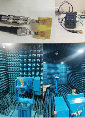
Figure 8: Photograph of the fabricated antenna and measurement setup of the proposed MIMO antenna.
Figure 9 (a) indicates that the suggested MIMO antenna has a reflection coefficient of less than -10 dB at 2.4 and 3.3 GHz. The mutual coupling of the proposed MIMO antenna, both simulated and measured, is compared in Fig. 9 (b). Figure 9 (b) indicates that the suggested MIMO antenna exhibits mutual coupling of less than -15 dB at 2.4 and 3.3 GHz. A high degree of agreement can be found between the results of the simulated and measured reflection coefficients as well as the mutual coupling studies.
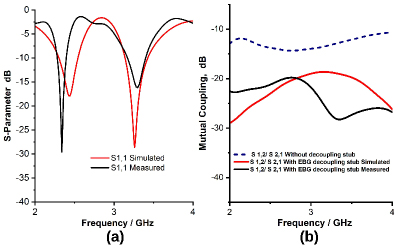
Figure 9: (a)-(b) Simulated and measured reflection coefficient and mutual coupling of the proposed MIMO antenna.
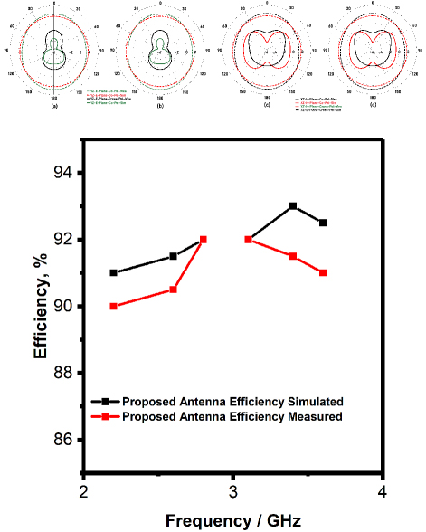
Figure 10: (a)-(d) Radiation pattern of the proposed antenna at 2.4, and 3.3 GHz in E- and H-plane, and (e) Efficiency of the proposed antenna at 2.4 and 3.3 GHz.
B. Radiation pattern and efficiency
The radiation pattern of the proposed MIMO is assessed in an anechoic room, as depicted in Fig. 8. The cross and co-polarization in E- and H-planes at 2.4 and 3.3 GHz is seen in Figs. 10 (a-d). Figures 10 (a-d), illustrates that the proposed antenna exhibits an omnidirectional radiation pattern at 2.4 and 3.3 GHz. Due to the metamaterial loading and the SIW cavity, cross-polarization and backlobe radiation are suppressed, resulting in the proposed antenna exhibiting an excellent co-polarization radiation pattern at 2.4 and 3.3 GHz. There is a high degree of concordance between the results of the simulated and measured radiationpatterns.
A representation of the simulated and observed efficiency of the proposed MIMO antenna can be found in Fig. 10 (e). According to the data presented in Fig. 10 (e), the suggested MIMO demonstrates an efficiency that surpasses 90% at all operational bands (2.4 and 3.3 GHz).
IV. DIVERSITY PERFORMANCE OF PROPOSED MIMO ANTENNA
A. Diversity gain
Diversity gain, which quantifies the improvement in system performance due to the application of diversity techniques, is a critical metric calculated using equation (4). The performance of an enhanced system is indicated by an increased diversity gain value. The optimal number for MIMO antenna performance should be approximately 10 to achieve expected results.
| (4) |
The diversity gain of the proposed MIMO antenna is illustrated in Fig. 11 (a). From Fig. 11 (a), it is evident that the proposed MIMO antenna demonstrates a diversity gain value of approximately 10 at frequencies of 2.4 and and 3.3 GHz.
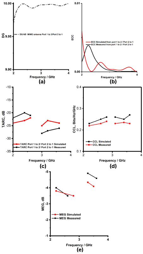
Figure 11: (a) ECC, (b) DG, (c) TARC, (d) CCL, and (e) MEG of the proposed MIMO antenna.
B. Envelope Correlation Coefficient (ECC)
The ECC, is a statistical measure that is used to quantify the degree of correlation that occurs between the components of the MIMO antenna:
| (5) | ||||
| (6) |
The determination can be achieved through scattering parameters by applying equation (5) in a lossless environment, characterized by a uniform distribution of power across antenna elements. This equation is applicable solely in scenarios where there is no loss present. Consequently, the ECC can be estimated based on the emitted far-field by utilizing equation (6). For uncorrelated MIMO antennas, the optimal value of the ECC is zero. However, for practical MIMO antennas, the ECC value must not exceed 0.5. Figure 11 (b) illustrates the proposed MIMO antenna based on the ECC design. The data presented in Fig. 11 (b) indicates that the proposed MIMO antenna demonstrates an ECC value of less than 0.04 at frequencies of 2.4 and 3.3 GHz.
C. TARC
An accurate evaluation of the correlation between the components of the MIMO antenna can be accomplished with the use of a statistical measure known as TARC. It is possible to compute the TARC of the MIMO antenna system for two ports by utilizing equation (7). In order to get optimal performance, the TARC of the MIMO antenna must be lower than 0 dB:
| (7) |
Figure 11 (c) illustrates the TARC of the MIMO antenna. The data presented in Fig. 11 (c) indicates that the proposed MIMO antenna achieves a TARC of less than -15 dB. As a result, the proposed MIMO antennas demonstrate a reduced correlation between the radiating elements.
D. CCL
The primary function of MIMO antennas is to enhance the capacity of the communication channel. Nevertheless, losses are a consequence of the correlation that exists between the elements of the antenna. For the purpose of estimating the highest practical limit for signal transmission while simultaneously reducing significant loss, a metric known as channel capacity loss (CCL) is utilized. The calculation of CCL can be carried out by utilizing equation (8). In real applications, the CCL should be kept at a level that is lower than 0.4 Bits/Hz/Sec:
| (8) | ||||
Figure 11 (d) illustrates a representation of the CCL of the MIMO antenna. The data presented in Fig. 11 (d) indicates that the proposed MIMO antenna achieves a CLL of less than 0.4 Bit/Hz/Sec at frequencies of 2.4 and 3.3 GHz.
E. MEG
The MEG statistic is another important statistic that is used to evaluate the performance of MIMO antennas. This statistic calculates the average signal strength that is received by each radiator within the antenna. The mathematical expression known as MEGi represents the ratio of the mean power that is received by the ith element to the mean power that is incident on the jth element from the same source. It is possible to calculate MEG by using equation (9), and the MEG value ought to be lower than dB in order to achieve the best possible MIMO performance:
| (9) |
The MEG of the MIMO antenna is depicted in Fig. 11 (e). The data presented in Fig. 11 (e) indicates that the proposed MIMO antenna exhibits a MEG of less than -3 dB at frequencies of 2.4 GHz and 3.3 GHz.
Table 2: Comparison of the proposed work with existing work
| LG21.9 | W21 | WG13 | |
| = | LG3 12.1 | = | WG2 |
| LG41 | WG3 | ||
| LG5 | WG4 | ||
| LG618 | WG7 | ||
| WG8 | |||
| LG82 | WG101 | ||
| LG9 1 | |||
| LG11.4 | W110 | WG44 | D12 |
| D3 | D5 | D61 | |
| D8 | |||
| D11=3 | |||
V. COMPARISON OF THE PROPOSED WORK WITH EXISTING WORK
Table 2 illustrates a comparison of the performance metrics between the proposed MIMO antenna and the existing MIMO antennas. The data presented in Table 2 indicates that the recommended MIMO antenna outperforms the currently utilized antennas regarding size, innovative methodology, and gain.
VI. CONCLUSION
In this work, a SIW cavity-backed gain-enhanced circularly polarized metamaterial-loaded dual-band MIMO antenna is designed for WLAN and sub-6 GHz 5G applications. The dual operating bands are enabled by placing a modified CSRR-shaped slot at the center of the SIW cavity-backed rectangular radiator. Additionally, the antenna incorporates modified SSRR unit cells strategically located in front of the intended radiators along the -axis. This arrangement enabled circular polarization and enhanced the gain of the proposed radiator at 2.4 GHz and 5 GHz. The metamaterial loading of the proposed antenna yields a gain of 5.5 dB at 2.4 GHz and 5.4 dB at 5 GHz. The cavity-backed configuration of the suggested antenna yields a unidirectional radiation pattern, contributing to its efficiency surpassing at frequencies of 2.4 and 5 GHz. Further, the implementation of a CSRR EBG decoupling structure reduces the mutual coupling between the radiators. The antenna exhibits exceptional diversity performance, as evidenced by various performance metrics: an ECC of 0.001, a DG of 9.98, a CCL of bits , a MEG of dB, and a TARC of . The experimental validation of the system confirms its intended functionality, showing a strong correlation between the simulated and measuredresults.
REFERENCES
[1] M. Kaushik, J. K. Dhanoa, and M. K. Khandelwal, “Partially omnidirectional and circularly polarized MIMO antenna covering sub-6-GHz band for 5G fast plan,” IEEE Transactions on Components, Packaging and Manufacturing Technology, vol. 13, no. 9, pp. 1443-1450, 2023.
[2] A. Kumar, C. Rai, and P. Chaurasia, “Realization of miniaturized triple-band four-port stacked MIMO antenna for WLAN applications at 2.9/5.0/5.9 GHz bands,” AEU - International Journal of Electronics and Communications, vol. 150, p. 154216, 2022.
[3] R. Khandelwal, “Metamaterial based circularly polarized four-port MIMO diversity antenna embedded with slow-wave structure for miniaturization and suppression of mutual coupling,” AEU - International Journal of Electronics and Communications, vol. 121, p. 153241, 2020.
[4] U. Ullah, M. Al-Hasan, S. Koziel, and I. B. Mabrouk, “Series-slot-fed circularly polarized multiple-input–multiple-output antenna array enabling circular polarization diversity for 5G 28 GHz indoor applications,” IEEE Transactions on Antennas and Propagation, vol. 69, no. 9, pp. 5607-5616, 2021.
[5] S. Virothu and M. Satya Anuradha, “Flexible CP diversity antenna for 5G cellular Vehicle-to-Everything applications,” AEU - International Journal of Electronics and Communications, vol. 152, p. 154248, 2022.
[6] M. Tiwari, K. Afroz, and M. Fatima, “Wideband metasurface loaded circularly polarized MIMO microstrip antenna with high isolation,” Microwave Review, vol. 28, pp. 22-27, 2022.
[7] J. Wang, Y. Cheng, H. Luo, F. Chen, and L. Wu, “High-gain bidirectional radiative circularly polarized antenna based on focusing metasurface,” AEU - International Journal of Electronics and Communications, vol. 151, p. 154222, 2022.
[8] S. Luo, Y. Li, Y. Xia, and L. Zhang, “A low mutual coupling antenna array with gain enhancement using metamaterial loading and neutralization line structure,” Appl. Comput. Electromagn. Soc. J, vol. 34, pp. 411-418, 2019.
[9] M. Y. Li, Z. Q. Xu, Y. L. Ban, C. Y. D. Sim, and Z. F. Yu, “Eight-port orthogonally dual-polarised MIMO antennas using loop structures for 5G smartphone,” IET Microw. Antennas Propag, vol. 11, pp. 1810-1816, 2017.
[10] S. Mukherjee and A. Biswas, “Design of planar high-gain antenna using SIW cavity hybrid mode,” IEEE Trans. Antennas Propag, vol. 66, no. 2, pp. 972-977, 2018.
[11] A. Kumar, Divya Chaturvedi, and S. Raghavan, “SIW cavity-backed circularly polarized square ring slot antenna with wide axial-ratio bandwidth,” AEU - International Journal of Electronics and Communications, vol. 94, pp. 122-127, 2018.
[12] G. Q. Luo, Z. F. Hu, W. J. Li, X. H. Zhang, L. L. Sun, and J. F. Zheng, “Bandwidth-enhanced low-profile cavity-backed slot antenna by using hybrid SIW cavity modes,” IEEE Transactions on Antennas and Propagation, vol. 60, no. 4, pp. 1698-1708, 2012.
[13] S. Yun, D. Kim, and S. Nam, ‘‘Bandwidth enhancement of cavity backed slot antenna using a via-hole above the slot,” IEEE Antennas Wireless Propagation Letter, vol. 11, pp. 1092-1095, 2012.
[14] H. Liu, H. Tian, L. Liu, and L. Feng, “Co-design of wideband filtering dielectric resonator antenna with high gain,” IEEE Trans. CircuitsSyst. II Express Briefs, vol. 69, pp. 1064-1068, 2022.
[15] C. Shi, J. Zou, J. Gao, and C. Liu, “Gain enhancement of a dual-band antenna with the FSS,” Electronics, pp.28-34, 2022.
[16] B. A. F. Esmail, S. Koziel, and D. Isleifson, “Metamaterial-based series-fed antenna with a high gain and wideband performance for millimeter-wave spectrum applications,” Electronics, vol. 12, no. 23, pp. 4836-4841 2023.
[17] B. A. F. Esmail, S. Koziel, and A. Pietrenko-Dabrowska, “Wideband high-gain low-profile series-fed antenna integrated with optimized metamaterials for 5G millimeter wave applications,” Scientific Report, vol. 14, pp. 185-192, 2024.
[18] A. Gorai, A. Deb, and J. R. Panda, ‘‘Millimeter wave/5G multiband SIW antenna with metasurface loading for circular polarization and bandwidth enhancement,” Journal of Infrared Milli Terahertz Waves, vol. 43, pp. 366-383, 2022.
[19] F. Ez-Zaki, “Double negative DNG metamaterial-based Koch fractal MIMO antenna design for sub-6 GHZ V2X communication,” IEEE Access, vol. 11, pp. 77620-77635, 2023.
[20] I. E. Lamri and A. Mansoul, “Design of CPW-fed dual-band four-element MIMO microstrip patch antenna for WLAN/WiMAX applications,” Institute of Electrical and Electronics Engineers Inc, pp. 83-86, 2023.
[21] V. Kikan, A. Dagar, S. Singh, S. Singh, N. C. Deo, A. Kumar, and M. Sharma, “A four-port novel inset-fed, rectangular MIMO-antenna designed for 2.40 GHz Bluetooth & Wi-Fi applications,” in 2023 Second International Conference on Electrical, Electronics, Information Communication Technology (ICEEICT), pp. 1–6, 2023.
[22] A. Pal and V. S. Tripathi, ‘‘Quad-element MIMO antenna with diverse radiation pattern characteristics and enhanced gain for 5.9 GHZ V2X communications,” AEU-Int. J. Electron. Commun, vol. 176, p. 155119, 2024.
[23] X. Mao, Z. Zhang, and J. Wang, “Dual-polarized reconfigurable MIMO decoupled antenna design using characteristic mode analysis,” IEEE conference, pp. 35–41, 2023.
[24] A. Kumar, P. V. Neeraj, and S. C. Padhy, “Four port MIMO antenna for IoT applications in public safety band and sub-6 GHz TDD 5G band,” Eng. Res. Express, vol. 6, p. 015309, 2024.
[25] R. Khan, W. T. Sethi, and W. A. Malik, “Enhancing gain and isolation of a quad-element MIMO antenna array design for 5G sub-6 GHz applications assisted with characteristic mode analysis,” Scientific Report, vol. 14, pp. 108–117,2024.
BIOGRAPHIES

Infant Leo S received the Bachelor of Engineering degree in Electronics and Communication Engineering and Master of Engineering degree in Communication Systems from the Anna University, Chennai, Tamil Nadu, India, in 2015 and 2019, respectively, and is currently pursuing the Doctor of philosophy from the National Institute of Technology Tiruchirappalli, Tamil Nadu, India. He is currently working as an Assistant Professor in the Department of Electrical, Electronics and Communication Engineering at Galgotias University in Greater Noida, Gautam Buddh Nagar, Uttar Pradesh. He has been interested in RF Microwave antennas circuit design and electromagnetics for more than 8 years.

G. Aloy Anuja Mary received the B.E. and M.E. degrees in Electronics Engineering from the Manonmaniam and Anna University in 2003 and 2005, respectively, and Ph.D from Anna University, Chennai, Tamil Nadu, India. She is currently Professor in ECE at Vel tech Rangarajan Dr.Sagunthala R&D Institute of Science and Technology,Chennai. She has been interested in the WirelessCommunication and Network Security for more than 15 years.

A. Syed Mazhar received the B.E, M.E and Ph.D. (Pursuing) in Electronics and Communication Engineering from the Anna University, Chennai, Tamil Nadu India, in 2008 and 2012, respectively, and an MBA in Project Management from the Alagappa University, Karaikudi, Tamil Nadu, India. He is currently working as an Assistant Professor Gr-3 in ECE at Galgotias University, Greater Noida, U.P, India. He has been interested in medical electronics, microprocessor and microcontroller and satellite communications for more than 13 years.

Satyam Mishra received the Bachelor of Technology degree in Electronics and Communication Engineering from the Dr.A.P.J.Abdul Kalam Technical University at Uttar Pradesh, India, in 2017 and Master of Technology degree in Signal Processing and Digital design from the Delhi Technological University at Delhi, India, in 2022 and is currently pursuing the Doctor of philosophy from the National Institute of Technology Delhi, India. He is currently working as an Assistant Professor in the Department of Electrical, Electronics and Communication Engineering at Galgotias University in Greater Noida, Gautam Buddh Nagar, Uttar Pradesh. He has been interested in the numerical aspects of antenna design and electromagnetic Machine Learning for more than 5 years.

G. Jothi received the B.E. and M.E. degrees in Computer Science Engineering from Anna University, Chennai, Tamil Nadu India. She is an adjunct professor in ECE at Saveetha School of Engineering, Saveetha Institute of Medical and Technical Sciences, Chennai.
ACES JOURNAL, Vol. 40, No. 4, 363–372
doi: 10.13052/2024.ACES.J.400410
© 2025 River Publishers